EP0108266A2 - Dispositif de dégazage de liquides circulants - Google Patents
Dispositif de dégazage de liquides circulants Download PDFInfo
- Publication number
- EP0108266A2 EP0108266A2 EP83110023A EP83110023A EP0108266A2 EP 0108266 A2 EP0108266 A2 EP 0108266A2 EP 83110023 A EP83110023 A EP 83110023A EP 83110023 A EP83110023 A EP 83110023A EP 0108266 A2 EP0108266 A2 EP 0108266A2
- Authority
- EP
- European Patent Office
- Prior art keywords
- degassing
- container
- valve
- pressure
- pump
- Prior art date
- Legal status (The legal status is an assumption and is not a legal conclusion. Google has not performed a legal analysis and makes no representation as to the accuracy of the status listed.)
- Withdrawn
Links
- 238000007872 degassing Methods 0.000 title claims abstract description 145
- 239000007788 liquid Substances 0.000 title claims abstract description 58
- 238000009434 installation Methods 0.000 claims abstract description 4
- 238000009423 ventilation Methods 0.000 claims abstract description 3
- 239000013505 freshwater Substances 0.000 claims description 19
- XLYOFNOQVPJJNP-UHFFFAOYSA-N water Substances O XLYOFNOQVPJJNP-UHFFFAOYSA-N 0.000 claims description 17
- 239000012528 membrane Substances 0.000 claims description 10
- 238000013022 venting Methods 0.000 claims description 8
- 239000012267 brine Substances 0.000 claims description 6
- HPALAKNZSZLMCH-UHFFFAOYSA-M sodium;chloride;hydrate Chemical compound O.[Na+].[Cl-] HPALAKNZSZLMCH-UHFFFAOYSA-M 0.000 claims description 6
- 238000007789 sealing Methods 0.000 claims description 5
- 238000004891 communication Methods 0.000 claims description 3
- 239000000945 filler Substances 0.000 claims description 2
- 239000007789 gas Substances 0.000 description 58
- 238000010438 heat treatment Methods 0.000 description 19
- 238000000034 method Methods 0.000 description 11
- 241001295925 Gegenes Species 0.000 description 4
- 210000003027 ear inner Anatomy 0.000 description 4
- 239000002655 kraft paper Substances 0.000 description 4
- 210000002023 somite Anatomy 0.000 description 3
- 238000010521 absorption reaction Methods 0.000 description 2
- 230000006870 function Effects 0.000 description 2
- 230000015654 memory Effects 0.000 description 2
- 230000000630 rising effect Effects 0.000 description 2
- 241000446313 Lamella Species 0.000 description 1
- 240000006240 Linum usitatissimum Species 0.000 description 1
- 230000002745 absorbent Effects 0.000 description 1
- 239000002250 absorbent Substances 0.000 description 1
- 238000009825 accumulation Methods 0.000 description 1
- 238000013459 approach Methods 0.000 description 1
- QVGXLLKOCUKJST-UHFFFAOYSA-N atomic oxygen Chemical compound [O] QVGXLLKOCUKJST-UHFFFAOYSA-N 0.000 description 1
- 238000000889 atomisation Methods 0.000 description 1
- 230000006399 behavior Effects 0.000 description 1
- 238000005260 corrosion Methods 0.000 description 1
- 230000007797 corrosion Effects 0.000 description 1
- 238000013461 design Methods 0.000 description 1
- 238000010586 diagram Methods 0.000 description 1
- 238000009792 diffusion process Methods 0.000 description 1
- 230000000694 effects Effects 0.000 description 1
- 239000006260 foam Substances 0.000 description 1
- 238000004519 manufacturing process Methods 0.000 description 1
- 239000001301 oxygen Substances 0.000 description 1
- 229910052760 oxygen Inorganic materials 0.000 description 1
- 238000000926 separation method Methods 0.000 description 1
- 239000007921 spray Substances 0.000 description 1
- 230000008719 thickening Effects 0.000 description 1
- 238000004804 winding Methods 0.000 description 1
Images




Classifications
-
- B—PERFORMING OPERATIONS; TRANSPORTING
- B01—PHYSICAL OR CHEMICAL PROCESSES OR APPARATUS IN GENERAL
- B01D—SEPARATION
- B01D19/00—Degasification of liquids
- B01D19/0063—Regulation, control including valves and floats
-
- F—MECHANICAL ENGINEERING; LIGHTING; HEATING; WEAPONS; BLASTING
- F24—HEATING; RANGES; VENTILATING
- F24D—DOMESTIC- OR SPACE-HEATING SYSTEMS, e.g. CENTRAL HEATING SYSTEMS; DOMESTIC HOT-WATER SUPPLY SYSTEMS; ELEMENTS OR COMPONENTS THEREFOR
- F24D19/00—Details
- F24D19/08—Arrangements for drainage, venting or aerating
- F24D19/082—Arrangements for drainage, venting or aerating for water heating systems
- F24D19/083—Venting arrangements
Definitions
- the invention relates to a degassing device for liquid flows, in particular a device for venting heat exchange circuits, such as those found in heating systems.
- Hydraulic systems especially heating systems, can generally never be filled in such a way that no air bubbles remain in the system.
- gas in particular oxygen, enters the pipe due to leaks and diffusion (e.g. with floor heating in plastic pipes) and causes noise, corrosion of the system parts and a reduction in the efficiency of the system.
- the "absorption degassing" sold under the trade name SPIROVENT was proposed.
- This device runs total liquid flow through a degassing tank. Means are provided in the degassing container to create a laminar flow in which gas bubbles can easily rise. Since the device is installed after the boiler, i.e. at the point of the highest water temperature, the water flowing through is only slightly ready to absorb gases dissolved therein. The rising gas bubbles collect in a room that can be connected to the environment by a float valve when the liquid level drops, so that the gas can escape if there is sufficient gas accumulation.
- Such a system is intended to remove the air bubbles enclosed in the circuit by supplying the circuit with gas-unsaturated medium so that the enclosed air can be absorbed by the medium until saturation.
- gas-unsaturated medium so that the enclosed air can be absorbed by the medium until saturation.
- the solubility difference is only extremely small due to the low temperature difference between the flow and return, so that effective absorption cannot be expected .
- degassing device for liquid flows, in particular for venting heat exchange circuits with a pipeline for guiding the liquid flow and a degassing container with a gas outlet. solved in that the degassing container is at least temporarily in flow connection with the pipeline and is at least temporarily under a pressure below the pressure in the pipeline at the installation site.
- the heating system according to FIG. 1 has a boiler 7 with a burner, from which the heated water in the flow 10 is conveyed into the heat utilization system 12 by a circulation pump 5. From the heat utilization system 12, the water flows back into the boiler 11.
- the usual pressure expansion vessel 6 is connected to the flow 10.
- the degassing container 1 is switched into the circuit in such a way that at least part of the medium flows into the degassing container 1 via the inlet line 21 and flows out of the container again via the outlet line 31.
- the degassing container 1 since it works largely independently of temperature, can be attached essentially at any point in the system.
- the degassing container 1 has a housing 4, which is connected via the inlet line 21 to an inlet valve 20 to the circuit line 2, and the outlet line 31 to the outlet line 30 to the circuit line 2.
- a throttle 25 is provided in the circuit line 2 between the connection points of the inlet and outlet lines, so that at least a partial flow of the medium is led into the degassing container 1.
- the degassing container 1 has a filling feed 8 with a filling valve 17, and an outlet 9 with a drain valve 18 for filling or emptying the system.
- the wall 4 of the degassing container 1 has at least at one point a degassing piston 51 which is sealed off from the container wall 4 by means of an elastic sealing membrane 52.
- the degassing piston 51 is connected to drive means 15 in such a way that en can be drawn into or out of the container (dashed line in FIG. 2). By means of this piston movement is an enlargement causes b z w.Verring réelle the container volume.
- the degassing container 1 On its upper side, the degassing container 1 has a gas discharge valve 40, which is closed by a float when the liquid level is high, and a gas check valve 41 connected in series with this valve, which air flows out of the gas discharge 52, but no air flows into the degassing container 1e leaves.
- the filling valve 17 is opened, the outlet valve 18 is closed, inlet and outlet valves 21 and 31 are opened and the throttle 25 is closed. Because the fresh water flows into the interior of the degassing container 1 and has a very low flow rate there, gas bubbles in the fresh water can rise to the surface.
- the gas discharge valve 40 opens, which is controlled by a float in accordance with the liquid level 3 and the air escapes from the gas outlet 42 via the gas check valve 41. If the liquid level 3 rises again due to the fresh water supply, the gas outlet valve 40 closes until sufficient gas has again accumulated in the degassing container 1. In this way, a large part of the gas bubbles entrained in the liquid flow is already separated without the operation of the degassing by reducing the pressure.
- the degassing container 1 can be temporarily placed under negative pressure even while the system is being filled with fresh water, so that on the one hand the entrained gas bubbles rise faster due to expansion and enlargement of their diameter, and on the other hand gases dissolved in the water escape. This process is described in more detail below.
- the interior of the degassing container 1 can also be temporarily placed under normal pressure via the drain valve 18, so that the amount of gas dissolved in the fresh water according to the line pressure in the fresh water line is reduced to the amount of gas that can be dissolved in water at normal pressure.
- the valves 17, 20 and 30 are closed and the drain valve 18 is opened, with the piston 51 pulled out.
- the valve 18 is closed again, and the gas bubbles leave time - for Rising up.
- you open the drain valve 30 and actuate the drive means 15 such that the piston 51 is pushed into the container 1.
- the separated gas escapes through the gas outlet 42, on the other hand, part of the container content is pressed: through the drain valve 30 into the pipeline 2. This process is repeated for a long time catches up until the net is filled.
- the gas separation process can also proceed as follows: the throttle valve 25 is closed (if necessary partially), the valves 20, 30 are opened and the medium is allowed to flow through the container 1 (with the circulation pump 5 switched on).
- valve 18 is opened so that the pressure in the container drops.
- the degassing described above results from the pressure drop.
- the amount of medium discarded via valve 18 must then be replaced via inlet 8.
- valves 20 and 30 and the drive means 15 are advantageously controlled via a time-controlled sequence control, which is not described in more detail here. However, it is also possible to carry out the control independently as a function of the pressure (with the influence of the temperature of the medium), as is described below in a further embodiment of the device according to the invention.
- the device shown here in FIG. 2 is suitable both for fixed installation in a circuit and for the production of a mobile system which is only temporarily connected to an existing system (for filling and for venting).
- the system according to FIG. 3 differs from that according to FIG. 2 in the design of the drive means; the process sequence is essentially the same as that described above; To simplify the fresh water supply 8 and the drain 9 are not shown.
- the drive means are formed by two chambers 60/61 which are separated from one another by a piston 62 which is sealed by a membrane.
- the piston 62 is fixedly connected to the piston 51 of the degassing container 1.
- the chambers 60 and 61 are connected via check valves 64 and 65 to a drive line 68 in such a way that medium can flow back into the circuit line 2 from the chambers 60/61.
- the chambers are 60/61 connected to a three-way control valve 66 which connects the pipeline 2 either to the chamber 60 or to the chamber 61 via the drive feed line.
- a pump 5 is provided between the drive line 67 and the drive line 68, the pump 5 possibly also being identical to the circulation pump. In order to generate a greater pressure gradient between the drive line 68 and the drive line 67, the throttle valve 25 in the circuit line 2 is closed relatively far.
- control valve 66 is actuated in such a way that the chamber 60 is connected to the drive supply line 67, there is an increase in pressure in the chamber 60 relative to the chamber 61, so that the piston 51 is pulled out of the degassing container 1, a part of that in the Chamber 61 contained liquid volume flows through the check valve 65 into the drain line 68, or is even sucked out of the chamber 61 with further generation of force. If the valve 66 is switched over and the chamber 61 is connected to the drive supply line 67, the piston 51 is pressed into the degassing container 1, the excess volume in the chamber 60 escapes via the check valve 64 into the drive line 68 or becomes from the chamber 60 sucked out.
- valve 20 and the actual degassing process take place in one of the ways described above.
- the drive means shown here make it possible to equip a system that normally requires a pump with lower output (low pressure with the required delivery rate) only with a correspondingly more powerful circulation pump, without having to attach further, for example motorized, drive means.
- the control of the valves 20 and 66 can again be carried out as described above via a sequence control or pressure-temperature controlled as described below.
- FIG. 4 shows a system as described in FIG. 3, but this device has only one piston plate, which acts as a piston 51 in its central zone and as a drive means 62 in its annular edge zone.
- a single piston plate is clamped in a housing via a sealing membrane 63 to form the two chambers 60/61, the central zone forming the piston 51 is sealed via an annular membrane 52 to the cover of the housing and thus surrounds the degassing container 1. and derivatives are as described above; connected.
- the device shown only schematically in FIG. 4 can also be constructed, for example, in the form of spherical shells, which results in stiffening of the piston plates 62 and 51.
- a cylindrical housing cover 80 is screwed onto a housing body 81; an annular sealing membrane 52 is clamped between the two parts.
- the membrane 52 is enclosed in its central part by two piston plates 51, the piston plates -51 and the membrane 52 having a central bore through which the threaded pin of a piston tensioning device 87 projects, which is screwed into a piston holder 75.
- the piston plates 51 and the diaphragm 52 are firmly and tightly clamped by the screw connection.
- a non-magnetizable intermediate piece 69 with a groove 70 is screwed into the internal thread of the piston holder 75 on the side opposite the piston tensioning device 87 and has a magnet core 73 at its other end.
- the piston clamping device 87 On the side opposite the magnetic core 73, the piston clamping device 87 has a coaxial threaded bore into which a bolt is screwed, on which an inlet valve seal 77 is slidably attached.
- the bolt has a thickening at its upper end so that the washer 77 cannot slide beyond it.
- the disc 77 is so clamped against the piston clamping device 87 by spring means that it sits at the upper end of the bolt, ie the piston plates 51 opposite.
- a strong spring 71 is clamped between the upper piston plate 51 and the cover 80, so that the piston 51 is pressed downward in the normal state while increasing the volume of the degassing container 1.
- a valve seat 78 is fitted in the housing cover 80, into which the inlet line 21 opens, on the end of which an inlet check valve 79 (e.g. a compression-molded hose) is seated.
- the housing cover 80 also has an outlet line 31 which is closed by an outlet valve 30. Furthermore, the cover 80 is pierced by the gas discharge device 40/41, which will be described in more detail below.
- a toggle switch 74 is arranged below the piston plates 71 approximately at the level of the groove 70 and engages in the groove 70 with its toggle.
- the switch 74 is connected to the body 81 via a screw in an elongated hole.
- the winding 72 of a lifting magnet which interacts with the magnetic core 73 is fixed at the lower end of the body 81.
- the gas discharge device 40/41 has a cover 85 and a base 86 which are screwed together.
- a valve seat 82 is screwed into the center of the cylindrical cover 85 at the upper end, the valve seat 82 forming the gas outlet 42 with its upper end.
- a gas-tight, elastic buoyancy body 84 In the interior of the housing consisting of cover 85 and bottom 86 there is a gas-tight, elastic buoyancy body 84, which is designed here as a bellows.
- the buoyancy body 84 carries an air outlet valve seal 83 in the center on its upper end, which extends through a pin into the valve seat 82. At its lower end the buoyancy body 84 has a pin which is let into a central bore of the bottom 86 with play.
- the gas discharge device functions in such a way that, when the liquid level is high, the float 84 is lifted up, so that the valve 40, consisting of seal 83 and seat 82 is closed. At a low liquid level and an ambient pressure which is equal to the internal pressure in the buoyancy body 84, the valve 40 is opened; at an ambient pressure which is substantially below the internal pressure in the buoyancy body 84, the lower end of the buoyancy body 84 clamps against the bottom 86 and presses so valve seal 83 against the valve seat 82 and closes the gas outlet 42nd
- the device shown here is therefore automatic and requires no additional control. However, it must be ensured here that the seat of the seal 77 on the valve seat 78 is not absolutely tight (if necessary, this can be secured by a bypass), since otherwise a stable state can be achieved and the process no longer starts automatically.
- the automatic control shown here can, of course, also be used in a correspondingly modified manner for the devices according to FIGS. 2 to 4.
- a float valve is advantageously provided which closes the drain line 31a when the liquid level is low.
- the device shown here is advantageously operated with commercially available and therefore very reliable pumps, the jet pumps show no signs of wear, so that a high level of operational reliability of the entire system is guaranteed.
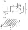
- the interior of the degassing container 1 is advantageously designed in such a way that the gas bubbles which are formed or carried along have to travel as short as possible to the surface of the liquid medium, but the surface is as large as possible.
- An apparatus which accomplishes this is shown in Figure 9, where an inflow 57 communicates with an outflow 58 via a labyrinth in a flat trough.
- a plurality of such labyrinths are advantageously connected in series or arranged one above the other.
- the degassing container 1 or 1a is connected to the pipeline 2 via an inlet line 21.
- a valve 20 which can be remotely arranged is attached in the feed line 21 and can connect the degassing container 1 or 1a to the pipeline 2 or separate it from the latter. In order to lower the pressure in the degassing tank, it is at least temporarily connected to the atmosphere.
- the valve 20 is connected via a control line 120 to a controller 100, which is preferably constructed as an electronic device.
- a pressure pump 94 is preferably connected on the suction side at the lowest point of the degassing container 1, and the discharge line 31 is connected to the pressure side of the pressure pump 94 and opens out again into the pipeline 2 (not shown) via a T-piece.
- a fresh water line 8 also opens into the pressure vessel 1 and is opened by a float-controlled valve 17 when the liquid level in the degassing vessel 1 has reached a minimum level. Furthermore, an overflow 9 is provided in the degassing container, which is arranged and dimensioned such that the incoming fresh water can flow off reliably even when the float valve 17 is jammed.
- a level indicator 95 is also arranged in the degassing container (here as a float-controlled one Switch drawn), which communicates the actual liquid level in the degassing tank 1 of the controller 100 via the control line 195.
- the pressure pump 94 is also controlled by the controller 100 via the control line 194. Furthermore, a pressure sensor 101 is arranged in the pipeline system in such a way that this pressure sensor 101 measures the pressure in the system essentially independently of the operating state of the valve 20 and the pump.
- the electronic controller 100 has various program memories (e.g. PROM's or EPROM's) and a timer.
- program memories e.g. PROM's or EPROM's
- the pipe 21 opens, as shown in Figure 10, preferably just after the pressure connection of the circulating pump 5 flows into the heating system, the return line 31 in the section of the conduit 2, which comes from the heat exchanger system ta ll 12th
- Another program is used in the controller 100 in continuous operation.
- the valve 20 is opened until a maximum level in the degassing container 1 is reached. Since the degassing container 1 is connected to the atmosphere, but the heating system is under high pressure, a large part of the gases dissolved in the liquid escapes in accordance with the lower pressure.
- the pump 94 is switched on and sucks the liquid out of the degassing container 1 or pushes the liquid back into the system against the system pressure, until the pressure in the system which the pressure sensor 101 measures corresponds to the intended pressure.
- the pump 94 will still suction even if the liquid level in the degassing container 1 has fallen below a point at which the Float valve 17 opens and fresh water flows in from line 8. As soon as the intended system pressure is reached, the pump 94 is switched off and the process described above is repeated.
- the pressure sensor 101 it is also possible to open and close the valve 20 very often or to regulate it proportionally and to let the pump 94 run almost continuously. This latter mode of operation, however, requires an unnecessarily long operating time for the pump 94.
- the medium in the degassing container 1 can completely outgas before the pump 94 is switched on.
- a controller 100 a pump 94, a pressure sensor 101 and remotely adjustable valves are provided, as has already been described above.
- the system shown in FIG. 11 is preferably also arranged in the heating system as shown in FIG. 10.
- the controller 100 opens the valve 20 when the valve 40 is initially closed, so that, due to the pressure difference generated by the circulating pump 5, the circulating medium flows through the line 21 into the degassing tank 1a and flows back into the system via the check valve 19 and the line 31. After a certain time it is ensured that there is essentially only medium with a relatively high proportion of dissolved gas in the degassing container 1a. At this time, the control 100 closes the valve 20 and then opens the valve 40. Via the line 42, the degassing container 1a is at atmospheric pressure, so that the gases dissolved in the liquid emerge from the liquid. Of course, a certain proportion of liquid will reach the second degassing container 1b via the line 42.
- the valve 40 is closed again and the valve 20 is opened, so that the first degassing tank 1a is again subjected to the full system pressure.
- the pressure sensor 101 measures the system pressure and the controller 100 compares the actual system pressure with a target value on the basis of the values programmed in beforehand. If the system pressure is below the setpoint, this means that there is not enough liquid in the system, whereupon the controller 100 starts the pressure pump 94 (in continuous operation it goes without saying valve 97 closed, valve 32 open).
- the pump 94 starts up, the liquid drained off via the line 42 during the previous degassing processes is returned to the circuit, if liquid is missing in the system, this is supplemented via the float valve 17 and the fresh water supply 8.
- the two-point behavior of the control ensures that the pressure pump 94 only has to start when the second degassing container 1b, which acts as a capacity, is relatively full.
- the pump 94 then continues to operate until the system pressure is fully restored. This method of operation places an extremely low load on the pressure pump 94, while the degassing effect is nevertheless optimal.
- the device according to FIGS. 11 and 12 can be modified accordingly, that is to say without a pressure pump 94.
- the preferred embodiments of the device according to the invention according to FIGS. 11 and 12 enable fully automatic operation of a heating system even if, for example, floor heating systems with the difficulties described at the outset are used without manual ventilation or refilling the system being necessary. Furthermore, these embodiments ensure that heating systems with brine filling can be filled particularly easily and during of the continuous venting operation, no liquid is lost through the venting process.
Landscapes
- Chemical & Material Sciences (AREA)
- Engineering & Computer Science (AREA)
- General Engineering & Computer Science (AREA)
- Thermal Sciences (AREA)
- Combustion & Propulsion (AREA)
- Mechanical Engineering (AREA)
- Physics & Mathematics (AREA)
- Chemical Kinetics & Catalysis (AREA)
- Degasification And Air Bubble Elimination (AREA)
- Discharge Heating (AREA)
- Magnetic Resonance Imaging Apparatus (AREA)
- Furnace Details (AREA)
- Superconductors And Manufacturing Methods Therefor (AREA)
- Crystals, And After-Treatments Of Crystals (AREA)
Applications Claiming Priority (2)
| Application Number | Priority Date | Filing Date | Title |
|---|---|---|---|
| DE19823237023 DE3237023A1 (de) | 1982-10-06 | 1982-10-06 | Entgasungsvorrichtung fuer fluessigkeitsstroeme |
| DE3237023 | 1982-10-06 |
Related Child Applications (2)
| Application Number | Title | Priority Date | Filing Date |
|---|---|---|---|
| EP86100677.3 Division-Into | 1983-10-06 | ||
| EP86100677A Division EP0187683B1 (fr) | 1982-10-06 | 1983-10-06 | Dispositif de dégazage |
Publications (2)
| Publication Number | Publication Date |
|---|---|
| EP0108266A2 true EP0108266A2 (fr) | 1984-05-16 |
| EP0108266A3 EP0108266A3 (fr) | 1984-08-22 |
Family
ID=6175091
Family Applications (2)
| Application Number | Title | Priority Date | Filing Date |
|---|---|---|---|
| EP83110023A Withdrawn EP0108266A3 (fr) | 1982-10-06 | 1983-10-06 | Dispositif de dégazage de liquides circulants |
| EP86100677A Expired - Lifetime EP0187683B1 (fr) | 1982-10-06 | 1983-10-06 | Dispositif de dégazage |
Family Applications After (1)
| Application Number | Title | Priority Date | Filing Date |
|---|---|---|---|
| EP86100677A Expired - Lifetime EP0187683B1 (fr) | 1982-10-06 | 1983-10-06 | Dispositif de dégazage |
Country Status (3)
| Country | Link |
|---|---|
| EP (2) | EP0108266A3 (fr) |
| AT (1) | ATE51156T1 (fr) |
| DE (2) | DE3237023A1 (fr) |
Cited By (7)
| Publication number | Priority date | Publication date | Assignee | Title |
|---|---|---|---|---|
| DE3422788A1 (de) * | 1984-06-20 | 1986-01-02 | Spiro Research B.V., Helmond | Verfahren und vorrichtung zum entlueften von geschlossenen fluessigkeits-umlaufsystemen |
| WO1988010143A1 (fr) * | 1987-06-26 | 1988-12-29 | Beckman Instruments, Inc. | Systeme de degazage de liquides |
| US4915713A (en) * | 1989-03-13 | 1990-04-10 | Beckman Instruments, Inc. | Liquid degassing system and method |
| US4955992A (en) * | 1987-06-26 | 1990-09-11 | Beckman Instruments, Inc. | Liquid degassing system |
| EP0663570A1 (fr) * | 1994-01-14 | 1995-07-19 | A. Schwarz + Co. | Commande pour dégazer le liquide dans un système de circuit de liquide |
| DE29510126U1 (de) * | 1995-06-22 | 1995-10-12 | Bernstein, Hans Friedrich, 82211 Herrsching | Armaturen, insbesondere für den Ausdehnungs- und Entspannungsbehälter eines Flüssigkeitskreislaufsystems |
| DE102009022765A1 (de) | 2009-05-27 | 2010-12-02 | Hans-Friedrich Bernstein | Solaranlage für eine Heiz- oder Kühlanlage |
Families Citing this family (14)
| Publication number | Priority date | Publication date | Assignee | Title |
|---|---|---|---|---|
| DE3716396A1 (de) * | 1987-05-15 | 1988-12-15 | Hans Friedrich Bernstein | Ausdehnungs- und druckhaltevorrichtung fuer zirkulierende fluessigkeitsstroeme |
| AT396521B (de) * | 1991-04-24 | 1993-10-25 | Schwarz A & Co | Vorrichtung zur entgasung von flüssigkeiten in flüssigkeitskreislaufsystemen |
| NL9301908A (nl) * | 1993-11-04 | 1995-06-01 | Spiro Research Bv | Werkwijze en inrichting voor het ontluchten van een vloeistof in een in hoofdzaak gesloten vloeistofcirculatiesysteem. |
| SE501484C2 (sv) * | 1994-02-07 | 1995-02-27 | Bjoern Carlsson | Anordning vid ett värme- eller kylsystem med en i en sluten ledningskrets kontinuerligt strömmande systemvätska |
| AT408585B (de) * | 1997-12-16 | 2002-01-25 | Schwarz A & Co | Verfahren zur steuerung einer vorrichtung zur druckhaltung und entgasung einer in einem flüssigkeitskreislaufsystem, insbesondere einer heizungsanlage, zirkulierenden flüssigkeit |
| AT409661B (de) * | 1997-11-26 | 2002-10-25 | Schwarz A & Co | Verfahren zur steuerung einer vorrichtung zur entgasung einer in einem flüssigkeitskreislaufsystem zirkulierenden flüssigkeit |
| DE19810005C2 (de) * | 1998-03-09 | 2001-08-23 | Udo Weingart | Verfahren zur Abscheidung von Gasen aus Heizwasser in Wasserheizungsanlagen |
| DE102005046112A1 (de) * | 2005-09-27 | 2007-03-29 | Thermo Electron (Karlsruhe) Gmbh | Temperiervorrichtung |
| SE531438C2 (sv) * | 2006-08-08 | 2009-04-07 | Ttm Energiprodukter Ab | Förfarande för avgasning av vätska i värme- och kylsystem, jämte anordning |
| US8562716B2 (en) | 2008-07-24 | 2013-10-22 | Spiro Enterprises B.V. | Device and method for degassing a liquid |
| DE102008061361A1 (de) * | 2008-12-10 | 2010-06-17 | Krones Ag | Alkoholannahme |
| DE102011088959B4 (de) | 2011-12-19 | 2022-08-04 | Endress+Hauser Conducta Gmbh+Co. Kg | Vorrichtung zum Entgasen einer Flüssigkeit und Verwendung dieser Vorrichtung in einem Analysegerät |
| DE102019118945A1 (de) * | 2019-07-12 | 2021-01-14 | Vaillant Gmbh | Verfahren und Vorrichtung zur Entgasung einer Flüssigkeit in einem Kreislauf, insbesondere in einem Heizkreislauf eines Wärmepumpensystems |
| WO2021062074A1 (fr) * | 2019-09-27 | 2021-04-01 | St. Jude Medical, Cardiology Division, Inc. | Système de cathéter irrigué comprenant un appareil de dégazage de fluide et méthodes l'utilisant |
Family Cites Families (7)
| Publication number | Priority date | Publication date | Assignee | Title |
|---|---|---|---|---|
| GB984307A (en) * | 1962-05-11 | 1965-02-24 | A M Castle & Company | Deaerating apparatus for liquids |
| DE1244368B (de) * | 1964-10-09 | 1967-07-13 | Svein Dyrhoff | Luftausscheidungsvorrichtung bei Expansionsgefaessen |
| DE1679636B1 (de) * | 1965-06-09 | 1971-01-14 | Julius Dopslaff | Verfahren und Vorrichtung zum Entgasen von Wasser in Warmwasserversorgungsanlagen |
| US4054522A (en) * | 1975-09-03 | 1977-10-18 | Harry Pinkerton | Apparatus for exposing a fluid to a negative pressure |
| DE2756965A1 (de) * | 1977-12-21 | 1979-06-28 | Dornier Gmbh | Verfahren und vorrichtung zum abscheiden in fluessigkeiten geloester gase |
| DE2810583A1 (de) * | 1978-03-11 | 1979-09-20 | Spiro Research Bv | Verfahren und vorrichtung zum entgasen von umlaufsystemen fuer fluessigkeiten |
| NL187518C (nl) * | 1978-05-02 | 1991-11-01 | Wetering Gemeenschappelijk Bez | Inrichting voor het afscheiden van lucht uit een vloeistofkringloop. |
-
1982
- 1982-10-06 DE DE19823237023 patent/DE3237023A1/de not_active Withdrawn
-
1983
- 1983-10-06 AT AT86100677T patent/ATE51156T1/de not_active IP Right Cessation
- 1983-10-06 EP EP83110023A patent/EP0108266A3/fr not_active Withdrawn
- 1983-10-06 EP EP86100677A patent/EP0187683B1/fr not_active Expired - Lifetime
- 1983-10-06 DE DE8686100677T patent/DE3381346D1/de not_active Expired - Lifetime
Non-Patent Citations (1)
| Title |
|---|
| None |
Cited By (12)
| Publication number | Priority date | Publication date | Assignee | Title |
|---|---|---|---|---|
| DE3422788A1 (de) * | 1984-06-20 | 1986-01-02 | Spiro Research B.V., Helmond | Verfahren und vorrichtung zum entlueften von geschlossenen fluessigkeits-umlaufsystemen |
| GB2184038A (en) * | 1984-06-20 | 1987-06-17 | Spiro Research Bv | Method and apparatus for degassing closed liquid circulation systems |
| AU581480B2 (en) * | 1984-06-20 | 1989-02-23 | Spiro Research B.V. | Method and apparatus for de-aeration of closed liquid- circulation system |
| GB2184038B (en) * | 1984-06-20 | 1989-10-18 | Spiro Research Bv | Method and apparatus for degassing closed liquid circulation systems of heating installations |
| AT390318B (de) * | 1984-06-20 | 1990-04-25 | Spiro Research Bv | Verfahren und vorrichtung zum entlueften von geschlossenen fluessigkeitsumlaufsystemen |
| WO1988010143A1 (fr) * | 1987-06-26 | 1988-12-29 | Beckman Instruments, Inc. | Systeme de degazage de liquides |
| US4955992A (en) * | 1987-06-26 | 1990-09-11 | Beckman Instruments, Inc. | Liquid degassing system |
| US4915713A (en) * | 1989-03-13 | 1990-04-10 | Beckman Instruments, Inc. | Liquid degassing system and method |
| EP0663570A1 (fr) * | 1994-01-14 | 1995-07-19 | A. Schwarz + Co. | Commande pour dégazer le liquide dans un système de circuit de liquide |
| AT401293B (de) * | 1994-01-14 | 1996-07-25 | Schwarz A & Co | Verfahren und vorrichtung zur entgasung der flüssigkeit in einem flüssigkeitskreislauf |
| DE29510126U1 (de) * | 1995-06-22 | 1995-10-12 | Bernstein, Hans Friedrich, 82211 Herrsching | Armaturen, insbesondere für den Ausdehnungs- und Entspannungsbehälter eines Flüssigkeitskreislaufsystems |
| DE102009022765A1 (de) | 2009-05-27 | 2010-12-02 | Hans-Friedrich Bernstein | Solaranlage für eine Heiz- oder Kühlanlage |
Also Published As
| Publication number | Publication date |
|---|---|
| EP0108266A3 (fr) | 1984-08-22 |
| DE3237023A1 (de) | 1984-04-12 |
| DE3381346D1 (de) | 1990-04-26 |
| EP0187683A3 (en) | 1986-10-29 |
| ATE51156T1 (de) | 1990-04-15 |
| EP0187683A2 (fr) | 1986-07-16 |
| EP0187683B1 (fr) | 1990-03-21 |
Similar Documents
| Publication | Publication Date | Title |
|---|---|---|
| EP0187683B1 (fr) | Dispositif de dégazage | |
| DE69416781T2 (de) | Verfahren und Anlage zur Entlüftung einer Flüssigkeit in einem im wesentlichen geschlossenen Kreislauf | |
| EP0313599B1 (fr) | Dispositif de transfert d'expansion dans des circuits de liquide, notamment d'installations de chauffage ou de refrigeration | |
| DE3345161A1 (de) | Wirbel-separator/eliminator zum entfernen von gas aus fluessigkeiten | |
| CH709041A2 (de) | Verfahren und Vorrichtung zur Entgasung eines Mediums in einem Kreislauf. | |
| AT399217B (de) | Vorrichtung zur expansionsübernahme in flüssigkeitskreislaufsystemen | |
| DE69731262T2 (de) | Unter Druck betriebene Speisevorrichtung für Flüssigkeiten | |
| EP0933109A2 (fr) | Dispositif pour le dégazage de milieux liquides | |
| DE19739142B4 (de) | Verfahren und Vorrichtung zum Entgasen von in einer Flüssigkeit gelösten Gasen | |
| DE102004061874B4 (de) | Kraftstoffpumpenmodul | |
| DE1650656C3 (fr) | ||
| DE8228065U1 (de) | Entgasungsvorrichtung fuer fluessigkeitsstroeme | |
| DE4201424C2 (de) | Vorrichtung für ein kontinuierliches Vakuum-Reinigen von Öl | |
| DE2163235A1 (de) | Vorrichtung zum Belüften und zum Verhindern des Heberns in einem Warmwasserversorgungssystem | |
| DE2849824C2 (fr) | ||
| EP2896894B1 (fr) | Appareil de traitement de vapeur doté d'une prise d'eau fixe | |
| DE349771C (de) | Schwimmersteuerung fuer Fluessigkeitsbehaelter | |
| AT308007B (de) | Vorrichtung zum Belüften von in Rohrleitungen u.dgl. geführten Flüssigkeiten,insbesondere fü die Luftzufuhr zu Windkesseln von Wasserleitungssystemen | |
| DE69612620T2 (de) | Vorrichtung zum rücksaugen von wasser aus einem auslassrohr in verbindung mit einem wasserreiniger | |
| DE102007018164B3 (de) | Vorrichtung zur Regelung des Zuflusses einer Flüssigkeit in einen Behälter, insbesondere zur Zuflussregelung einer Wasseraufbereitungsanlage | |
| EP0183155B1 (fr) | Elévateur de liquide automatique | |
| DE530159C (de) | Verfahren zum Betrieb von zwei unter verschieden hohem Druck stehenden, an einen Dampferzeuger angeschlossenen Unterdruck-Dampfheizsystemen | |
| DE2040538B2 (de) | Ansaugvorrichtung für Kreiselpumpen | |
| DE225205C (fr) | ||
| DE22060C (de) | Neuerungen an selbstthätigen Regulir vorrichtungen für Dampfkessel - Speisepumpen |
Legal Events
| Date | Code | Title | Description |
|---|---|---|---|
| PUAI | Public reference made under article 153(3) epc to a published international application that has entered the european phase |
Free format text: ORIGINAL CODE: 0009012 |
|
| AK | Designated contracting states |
Designated state(s): AT BE CH DE FR GB IT LI LU NL SE |
|
| PUAL | Search report despatched |
Free format text: ORIGINAL CODE: 0009013 |
|
| AK | Designated contracting states |
Designated state(s): AT BE CH DE FR GB IT LI LU NL SE |
|
| 17P | Request for examination filed |
Effective date: 19841011 |
|
| RAP1 | Party data changed (applicant data changed or rights of an application transferred) |
Owner name: BERNSTEIN, HANS-FRIEDRICH |
|
| STAA | Information on the status of an ep patent application or granted ep patent |
Free format text: STATUS: THE APPLICATION IS DEEMED TO BE WITHDRAWN |
|
| 18D | Application deemed to be withdrawn |
Effective date: 19860308 |