EP0108312A2 - Dispositif de production d'un mélange - Google Patents
Dispositif de production d'un mélange Download PDFInfo
- Publication number
- EP0108312A2 EP0108312A2 EP83110526A EP83110526A EP0108312A2 EP 0108312 A2 EP0108312 A2 EP 0108312A2 EP 83110526 A EP83110526 A EP 83110526A EP 83110526 A EP83110526 A EP 83110526A EP 0108312 A2 EP0108312 A2 EP 0108312A2
- Authority
- EP
- European Patent Office
- Prior art keywords
- housing
- side walls
- hub
- chamber
- chambers
- Prior art date
- Legal status (The legal status is an assumption and is not a legal conclusion. Google has not performed a legal analysis and makes no representation as to the accuracy of the status listed.)
- Withdrawn
Links
Images


Classifications
-
- F—MECHANICAL ENGINEERING; LIGHTING; HEATING; WEAPONS; BLASTING
- F04—POSITIVE - DISPLACEMENT MACHINES FOR LIQUIDS; PUMPS FOR LIQUIDS OR ELASTIC FLUIDS
- F04C—ROTARY-PISTON, OR OSCILLATING-PISTON, POSITIVE-DISPLACEMENT MACHINES FOR LIQUIDS; ROTARY-PISTON, OR OSCILLATING-PISTON, POSITIVE-DISPLACEMENT PUMPS
- F04C11/00—Combinations of two or more machines or pumps, each being of rotary-piston or oscillating-piston type; Pumping installations
- F04C11/001—Combinations of two or more machines or pumps, each being of rotary-piston or oscillating-piston type; Pumping installations of similar working principle
-
- B—PERFORMING OPERATIONS; TRANSPORTING
- B01—PHYSICAL OR CHEMICAL PROCESSES OR APPARATUS IN GENERAL
- B01F—MIXING, e.g. DISSOLVING, EMULSIFYING OR DISPERSING
- B01F35/00—Accessories for mixers; Auxiliary operations or auxiliary devices; Parts or details of general application
- B01F35/71—Feed mechanisms
- B01F35/714—Feed mechanisms for feeding predetermined amounts
- B01F35/7141—Feed mechanisms for feeding predetermined amounts using measuring chambers moving between a loading and unloading position, e.g. reciprocating feed frames
- B01F35/71411—Feed mechanisms for feeding predetermined amounts using measuring chambers moving between a loading and unloading position, e.g. reciprocating feed frames rotating or oscillating about an axis
-
- F—MECHANICAL ENGINEERING; LIGHTING; HEATING; WEAPONS; BLASTING
- F04—POSITIVE - DISPLACEMENT MACHINES FOR LIQUIDS; PUMPS FOR LIQUIDS OR ELASTIC FLUIDS
- F04C—ROTARY-PISTON, OR OSCILLATING-PISTON, POSITIVE-DISPLACEMENT MACHINES FOR LIQUIDS; ROTARY-PISTON, OR OSCILLATING-PISTON, POSITIVE-DISPLACEMENT PUMPS
- F04C5/00—Rotary-piston machines or pumps with the working-chamber walls at least partly resiliently deformable
-
- F—MECHANICAL ENGINEERING; LIGHTING; HEATING; WEAPONS; BLASTING
- F04—POSITIVE - DISPLACEMENT MACHINES FOR LIQUIDS; PUMPS FOR LIQUIDS OR ELASTIC FLUIDS
- F04C—ROTARY-PISTON, OR OSCILLATING-PISTON, POSITIVE-DISPLACEMENT MACHINES FOR LIQUIDS; ROTARY-PISTON, OR OSCILLATING-PISTON, POSITIVE-DISPLACEMENT PUMPS
- F04C2230/00—Manufacture
- F04C2230/70—Disassembly methods
Definitions
- the invention relates to a device for producing a mixture of at least two masses which are metered separately and mixed together in a predetermined ratio with at least one variable volume chamber provided for each mass, which is movably mounted in a housing in which an inlet and a sequence is provided which opens into the chamber in corresponding positions.
- Devices of this type have a rotor which is mounted eccentrically in a housing.
- This eccentric bearing of the rotor causes movements of rotor parts, which are made up of rotary movements on the one hand and transverse movements on the other.
- these combined movements are relatively susceptible to faults, so that it must be expected that the rotor or some parts of the rotor will get stuck within the housing at certain intervals. This risk is all the greater since materials are used for the production of the housing on the one hand and the rotor on the other hand, one of which does not show a good sliding behavior compared to the other.
- plastic parts acting against one another it must be expected that the surfaces sliding on one another will either wear excessively or heat up, so that one surface may even seize up on the other.
- the object of the present invention is therefore to improve the device of the type mentioned in the introduction so that it can be used for metering highly abrasive masses.
- the chambers have flexible side walls, the plane of which is perpendicular to the respective feed direction.
- Such side walls can be used to manufacture devices that can be used universally.
- the side walls can be made of a highly abrasion-resistant material, which prevents the walls from being weakened so much when metering highly abrasive masses that they are no longer suitable for transporting the masses to be metered.
- a device equipped with such side walls can be used for the metering of self-curing compositions which have to be in an exact mixing ratio to one another so that they can harden after the mixture has been produced.
- These self-curing compounds can be used, for example, to mark lanes. They then consist of pasty mixture components that are mixed with highly abrasive components, such as the smallest glass fragments and moraine.
- abrasive components ensure that the mixture has a high coefficient of friction after it has hardened, so that it is suitable for the production of road markings.
- the processing of the mixture components is very difficult. Unprotected devices wear out very quickly, even if they are made from very hard steels.
- the application of abrasion-resistant plastics is the only way to keep the abrasion rate as low as possible. Such plastic surfaces cannot be used in conventional devices, however, because they heat up too much due to the friction that occurs. For the device, therefore, completely new design principles had to be used, with the aid of which it was possible, on the one hand, to create variable-volume chambers and, on the other hand, to carry out movements in which the heating is kept within permissible limits.
- the device that can be produced in this way is not only suitable for mixing pasty masses. Rather, it is also possible to meter injectable compositions. The necessary tight fits can be done with the flexible Walls are observed. In this way, for example, sprayable multi-component paints can be dosed using the device.
- the device required for metering the powder can also be produced without an eccentric.
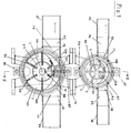
- This device essentially consists of two housings 1, 2, in which chambers 3, 4 are pivotally mounted about pivot axes.
- the pivot axes are formed by shafts 5, 6, which are driven by at least one motor 7.
- Sprockets 8, 9, which are connected to one another via a chain drive 10, can be fastened on the shafts 5, 6.
- the sprockets 8, 9 are provided with a different number of teeth 11, 12, the relationship of which determines the speed of the shafts 5, 7.
- Each of the two shafts 5, 6 is overhung in a bearing block 13, 14.
- the bearing blocks 13, 14 are connected to one another via a flange connection 15.
- the bearing blocks 13, 14 each consist of a sleeve 16, 17, in which the shafts 5, 6 via W ä lz - bearing 18, 19, 20, are mounted 21st
- a housing base plate 22, 23 is firmly connected to the bearing block 13, 14, for example via welds 24, 25.
- Each of the housing base plates 22, 23 spans a plane through which the shafts 5, 6 penetrate perpendicularly with their ends 26, 27 protruding from the bearing blocks 13, 14.
- These ends 26, 27 are concentrically surrounded by cylindrical housing parts 28, 29, which are guided in corresponding guides 30, 31 of the housing base plate 22, 23.
- the cylindrical housing parts 28, 29 are covered by end plates 32, 33, which are supported in similar guides 34, 35 on the cylindrical housing part 28, 29 as they are on the housing base plate 22, 23.
- the end plate 22, 23 is acted upon by a quick-release fastener 36, 37 in the direction of the cylindrical housing part 28, 29.
- This quick-release fastener 36, 37 consists of a screw 40, 41 provided with a rod 38, 39, which protrudes with a tip 42, 43 into a corresponding recess 44, 45 of the end plate 32, 33.
- the screw 40, 41 meshes with a thread 46, 47 which is formed in a yoke 48, 49 extending above the end plate 32, 33.
- In the yoke 48, 49 two bracket halves 50, 51; 52, 53 attached, which are guided along the outside of the cylindrical housing part 28, 29.
- the slot openings 58, 59 extend in a direction parallel to the shaft 5, 6 through the support lugs 66, 67.
- the support recesses 64, 65 are located on a side of the support lugs 66, 67 facing away from the end plates 32, 33.
- the slot openings 58, 59 have a width which corresponds to the cross section of the temple halves 50, 51; 52, 53 corresponds so that they can be inserted into the slot openings 58, 59.
- the ends of the slot openings 58, 59 are arranged so that the center points of the bearing depressions with the center point of the respectively assigned shaft 5, 6 lie on a diameter line.
- the slot openings extend either clockwise or counterclockwise in the same direction. This ensures that by pivoting the yoke 48, 49 about the screws 40, 41, the two bracket halves 50, 51; 52, 53 snap into slot openings 58, 59 in the same direction.
- Inlets 1, 2 open in a direction perpendicular to the axis of the cylindrical housing part 28, 29, inlets 68, 69 or outlets 70, 71. These inlets 68, 69 and outlets 70, 71 lie on a plane extending above the center line of the shafts 5, 6. Inlets 68, 69 and outlets 70, 71 form rectangular windows 72 which, apart from narrow edge areas 73, 74 and 75, 76, extend over the entire width and height of one . Half cylinder of the housing part 28, 29 extend. This large design of the windows 72 ensures that a large passage cross section is available for the mass entering the housing part 28, 29.
- inlet connectors 77, 78 or outlet connectors 79, 80 which are firmly connected to the cylindrical housing part 28, 29.
- Fittings 8], 82 and 83, 84 are fixedly connected to these outlet connections, by means of which the cross-sectional format assigned to the windows 72 is converted to a circular cross-section of connecting connections 85, 86 and 87, 88, respectively.
- connecting pieces 85, 86; 87, 88 are connected supply lines or discharge lines, not shown, through which the undosed mass is conveyed in the direction of the device or the metered quantities are conveyed away from it.
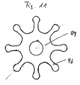
- a hub 89, 90 is fastened on the ends 26, 27 of the shaft 5, 6 within the cylindrical housing part 28, 29, for example with the aid of a wedge 91, 92.
- Slits 93 are formed in this hub, which extend in the direction of a central axis 94 of the hub 89, 90 extend in a star shape.
- the slots 93 have center lines 95 which intersect in the center axis 94 of the hub 89, 90.
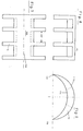
- an eccentric 105, 106 is fastened via a screw connection 107, 108.
- This eccentric 105, 106 is designed as a comb 109, which is provided with tines 111 on both sides of a back 1 iC.
- These tines 111 have a circular sector-shaped cross section 112.
- This circular sector-shaped cross section 112 has an outer boundary 113 which adapts to the inside 102 of the cylindrical housing part 28, 29. This has a smaller radius than an inner boundary 114 facing the inside of the cylindrical housing part 28, 29.
- the outer boundary 113 and the inner boundary 114 converge at an acute angle 115, 116.
- the side walls 96, 97 slide from the inside 102 onto the tines 111.
- the hub 89, 90 rotates further, the distance between the hub 89, 90 and the tines 111 increases again.
- the back 110 protrudes in its area up to the inner boundary 114 of the tines 111, in this way it is prevented that mass can push through between the tines 111.
- the closest distance between the inner boundary 114 and the hub 89, 90 is measured at the bending radius which is reasonable for the side walls 96, 97. In the case of a material which is easy to bend, it is conceivable not to make this distance substantially larger than the wall thickness of the side walls 96, 97. In this way, care is taken that even in the area of this distance not much mass is transported back from the outlet 70, 71 in the direction of the inlet 68, 69.
- the distance between the tines 111 is dimensioned on the one hand so that the side walls 96, 97 are well guided on them even in the event of a sharp bend.
- the tines 111 must maintain distances 117 from one another, which together create a free cross-section that is large enough to ensure satisfactory filling of the chambers 3, 4 with mass.
- the contents of one chamber 3, 4 are pressed out of the drain 70, 71.
- the pressure required for this arises from the fact that the cross section becomes smaller in accordance with the cross section of the tines 111, except that the mass builds up in front of the back 110, so that the pressure built up as a result only occurs through the outlet 70, 71 and on it subsequent connecting piece 85, 86; 87, 88 can compensate.
- the side walls 96, 97 running onto the tines 111 bend as the shaft 5, 6 rotates further in the direction of the chamber 3, 4 following in the direction of rotation 98. In this way, the volume of the chambers 3, 4 is considerably reduced, as a result of which the pressure of the mass in the outlet 7C, 71 increases.
- the side walls 96, 97 slowly straighten up again in accordance with the course of the inner boundary 114. This increases the volume of the chambers 3, 4 in the area of the inlet 68, 69.
- the enlargement of the chambers 3, 4 creates in the area of the inlet 68, 69 a negative pressure sucking the mass through the inlet 68, 69.
- the masses leaving the outlet 70, 71 are conveyed through the connecting piece 87, 88 in the direction of a mixing device in which they are mixed continuously and consumed immediately thereafter. In this way it is ensured that the curing of the masses only takes place at the place of use.
- the hub 89, 90 can also be provided with a wear-resistant coating.
- the side walls 96, 97 are made of a highly wear-resistant material, the strength of which is dimensioned on the one hand so that the side walls 96, 97 can convey the mass through the housing 1, 2.
- the side walls' must be flexible enough to be able to perform the bends in the area of the back 110th
- linings are also provided in all other parts of the housing 1, 2, for example on the inner sides of the housing base plate 22, 23 or end plate 32, 33 facing the chambers 3, 4. It is also possible for the hub 89, 90 and the To produce side walls 96, 97 together in the form of a piece. This creates a component that can be easily attached to the shaft 5, 6 and released again. This one-piece design improves the interchangeability of the wearing parts and thus the ease of maintenance of the device.
Landscapes
- Engineering & Computer Science (AREA)
- Mechanical Engineering (AREA)
- General Engineering & Computer Science (AREA)
- Chemical & Material Sciences (AREA)
- Chemical Kinetics & Catalysis (AREA)
- Processing And Handling Of Plastics And Other Materials For Molding In General (AREA)
- Feeding, Discharge, Calcimining, Fusing, And Gas-Generation Devices (AREA)
- Mixers Of The Rotary Stirring Type (AREA)
Applications Claiming Priority (2)
| Application Number | Priority Date | Filing Date | Title |
|---|---|---|---|
| DE19823239906 DE3239906A1 (de) | 1982-10-28 | 1982-10-28 | Vorrichtung zur herstellung eines gemisches |
| DE3239906 | 1982-10-28 |
Publications (2)
| Publication Number | Publication Date |
|---|---|
| EP0108312A2 true EP0108312A2 (fr) | 1984-05-16 |
| EP0108312A3 EP0108312A3 (fr) | 1986-11-12 |
Family
ID=6176790
Family Applications (1)
| Application Number | Title | Priority Date | Filing Date |
|---|---|---|---|
| EP83110526A Withdrawn EP0108312A3 (fr) | 1982-10-28 | 1983-10-21 | Dispositif de production d'un mélange |
Country Status (2)
| Country | Link |
|---|---|
| EP (1) | EP0108312A3 (fr) |
| DE (1) | DE3239906A1 (fr) |
Cited By (2)
| Publication number | Priority date | Publication date | Assignee | Title |
|---|---|---|---|---|
| WO2008103300A3 (fr) * | 2007-02-16 | 2008-11-06 | Gojo Ind Inc | Pompes centrifuges flexibles destinées à mélanger des composants individuels |
| RU2462618C2 (ru) * | 2010-02-24 | 2012-09-27 | Государственное образовательное учреждение высшего профессионального образования "Северо-Кавказский государственный технический университет" | Лопасть ротора импеллерного насоса |
Family Cites Families (5)
| Publication number | Priority date | Publication date | Assignee | Title |
|---|---|---|---|---|
| GB1214220A (en) * | 1968-08-01 | 1970-12-02 | Charles Wicksteed And Company | Improvements in rotary flexible blade pumps |
| DE2608503C3 (de) * | 1975-03-21 | 1981-01-29 | Dagma Deutsche Automaten- Und Getraenkemaschinen Gmbh & Co Kg, 2067 Reinfeld | Verfahren und Gerät zum Herstellen von Getränken unter dosiertem Abgeben und Mischen von Wasser und selbstkonservierenden Konzentraten oder Sirupen hoher Viskosität |
| SU914808A1 (ru) * | 1976-03-24 | 1982-03-23 | Pergunov Aleksandr | Ротативный насос 1 |
| JPS5529013A (en) * | 1978-08-18 | 1980-03-01 | Nitsukisou Eiko Kk | Improvement of impeller for rotary pump |
| CA1164729A (fr) * | 1980-05-05 | 1984-04-03 | James L. Bloemers | Pompe d'eau pour propulseur d'embarcation |
-
1982
- 1982-10-28 DE DE19823239906 patent/DE3239906A1/de not_active Withdrawn
-
1983
- 1983-10-21 EP EP83110526A patent/EP0108312A3/fr not_active Withdrawn
Cited By (3)
| Publication number | Priority date | Publication date | Assignee | Title |
|---|---|---|---|---|
| WO2008103300A3 (fr) * | 2007-02-16 | 2008-11-06 | Gojo Ind Inc | Pompes centrifuges flexibles destinées à mélanger des composants individuels |
| US8096530B2 (en) | 2007-02-16 | 2012-01-17 | Gojo Industries, Inc. | Flexible impeller pumps for mixing individual components |
| RU2462618C2 (ru) * | 2010-02-24 | 2012-09-27 | Государственное образовательное учреждение высшего профессионального образования "Северо-Кавказский государственный технический университет" | Лопасть ротора импеллерного насоса |
Also Published As
| Publication number | Publication date |
|---|---|
| DE3239906A1 (de) | 1984-05-03 |
| EP0108312A3 (fr) | 1986-11-12 |
Similar Documents
| Publication | Publication Date | Title |
|---|---|---|
| EP1458467B1 (fr) | Dispositif pour melanger deux matieres pateuses, notamment pour melanger une matiere pour empreinte dentaire avec une matiere catalytique | |
| EP1914056B1 (fr) | Dispositif de mélange continu et intensif de mortier sec | |
| DE2637558A1 (de) | Verfahren und vorrichtung zur erzeugung eines kontinuierlichen materialstroms | |
| DE202007002792U1 (de) | Vorrichtung zum Vermischen einer Binder- und einer Härter-Komponente zur Herstellung einer gebrauchsfertigen Spachtelmasse | |
| EP1884660A1 (fr) | Hélice transporteuse pour une pompe à cavité progressive | |
| EP0584573B1 (fr) | Dispositif pour la fabrication de mortier apte à être pompé sur le chantier | |
| EP3473396A1 (fr) | Arbre de vis sans fin à deux ailettes pour machine de mélange et de pétrissage | |
| EP0995565B1 (fr) | Appareil pour le traitement continu de materiaux coulants | |
| DE4318177A1 (de) | Vorrichtung zur baustellenseitigen Herstellung von pumpfähigen Mörtelmassen | |
| DE2830491C2 (fr) | ||
| DE202016000169U1 (de) | Pump- und/oder Mischeinrichtung zum Fördern, Homogenisieren und/oder Dispergieren fließfähiger Produkte | |
| EP2343170B1 (fr) | Procédé et dispositif de mélange continu de matières contenant de la glaise et de matériaux semblables à la glaise | |
| DE2513577C3 (de) | Kontinuierlich arbeitender Mischer für plastische Massen | |
| EP2476302B1 (fr) | Roue de comptage pour un dispositif de dosage destinée au dosage de semences | |
| DE1782125B2 (de) | Vorrichtung zum kontinuierlichen mischen und kneten plastischer fuell- und spachtelmassen o dgl | |
| DE2355671A1 (de) | Mischmaschine | |
| DE69509809T2 (de) | Vorrichtung zum Mischen von Leim | |
| DE102004051063A1 (de) | Innenmischer zum Kneten von plastischen Massen | |
| EP1900443B1 (fr) | Système d'appareils destiné à la fabrication de mastic prêt à l'emploi par le mélange de composants liants et durcisseurs | |
| DE202004002601U1 (de) | Vorrichtung zum Dosieren von Schüttgütern mit einem Rührwerk und einer Antriebseinheit | |
| EP0108312A2 (fr) | Dispositif de production d'un mélange | |
| DE102005005394B4 (de) | Pump- und Mischvorrichtung für pulver- bzw. rieselförmige Medien sowie System zur Bereitstellung pastöser Medien für Bauzwecke | |
| EP0410316B1 (fr) | Dispositif de mélange et dosage pour mortier de maçonnerie ou d'enduit ou similaire | |
| DE69412813T2 (de) | Radauftragsgerät zum auftragen von klebstoff, insbesondere auf buchrücken beim buchbinden | |
| DE8230234U1 (de) | Vorrichtung zur Herstellung eines Gemisches |
Legal Events
| Date | Code | Title | Description |
|---|---|---|---|
| PUAI | Public reference made under article 153(3) epc to a published international application that has entered the european phase |
Free format text: ORIGINAL CODE: 0009012 |
|
| AK | Designated contracting states |
Designated state(s): AT BE CH FR GB IT LI LU NL SE |
|
| PUAL | Search report despatched |
Free format text: ORIGINAL CODE: 0009013 |
|
| STAA | Information on the status of an ep patent application or granted ep patent |
Free format text: STATUS: THE APPLICATION IS DEEMED TO BE WITHDRAWN |
|
| AK | Designated contracting states |
Kind code of ref document: A3 Designated state(s): AT BE CH FR GB IT LI LU NL SE |
|
| 18D | Application deemed to be withdrawn |
Effective date: 19860808 |