EP0108337A2 - Dispositif pour le sablage de routes - Google Patents
Dispositif pour le sablage de routes Download PDFInfo
- Publication number
- EP0108337A2 EP0108337A2 EP83110671A EP83110671A EP0108337A2 EP 0108337 A2 EP0108337 A2 EP 0108337A2 EP 83110671 A EP83110671 A EP 83110671A EP 83110671 A EP83110671 A EP 83110671A EP 0108337 A2 EP0108337 A2 EP 0108337A2
- Authority
- EP
- European Patent Office
- Prior art keywords
- road
- liquid
- spreading
- sensor
- salt
- Prior art date
- Legal status (The legal status is an assumption and is not a legal conclusion. Google has not performed a legal analysis and makes no representation as to the accuracy of the status listed.)
- Granted
Links
Images
Classifications
-
- E—FIXED CONSTRUCTIONS
- E01—CONSTRUCTION OF ROADS, RAILWAYS, OR BRIDGES
- E01H—STREET CLEANING; CLEANING OF PERMANENT WAYS; CLEANING BEACHES; DISPERSING OR PREVENTING FOG IN GENERAL CLEANING STREET OR RAILWAY FURNITURE OR TUNNEL WALLS
- E01H10/00—Improving gripping of ice-bound or other slippery traffic surfaces, e.g. using gritting or thawing materials ; Roadside storage of gritting or solid thawing materials; Permanently installed devices for applying gritting or thawing materials; Mobile apparatus specially adapted for treating wintry roads by applying liquid, semi-liquid or granular materials
- E01H10/007—Mobile apparatus specially adapted for preparing or applying liquid or semi-liquid thawing material or spreading granular material on wintry roads
-
- B—PERFORMING OPERATIONS; TRANSPORTING
- B05—SPRAYING OR ATOMISING IN GENERAL; APPLYING FLUENT MATERIALS TO SURFACES, IN GENERAL
- B05B—SPRAYING APPARATUS; ATOMISING APPARATUS; NOZZLES
- B05B9/00—Spraying apparatus for discharge of liquids or other fluent material, without essentially mixing with gas or vapour
- B05B9/03—Spraying apparatus for discharge of liquids or other fluent material, without essentially mixing with gas or vapour characterised by means for supplying liquid or other fluent material
- B05B9/04—Spraying apparatus for discharge of liquids or other fluent material, without essentially mixing with gas or vapour characterised by means for supplying liquid or other fluent material with pressurised or compressible container; with pump
- B05B9/06—Spraying apparatus for discharge of liquids or other fluent material, without essentially mixing with gas or vapour characterised by means for supplying liquid or other fluent material with pressurised or compressible container; with pump the delivery being related to the movement of a vehicle, e.g. the pump being driven by a vehicle wheel
-
- G—PHYSICS
- G08—SIGNALLING
- G08B—SIGNALLING SYSTEMS, e.g. PERSONAL CALLING SYSTEMS; ORDER TELEGRAPHS; ALARM SYSTEMS
- G08B19/00—Alarms responsive to two or more different undesired or abnormal conditions, e.g. burglary and fire, abnormal temperature and abnormal rate of flow
- G08B19/02—Alarm responsive to formation or anticipated formation of ice
Definitions
- the invention relates to a device for regulating a road spreading device for salt or the like according to the preamble of claim 1.
- Such a device is known from DE-PS 26 48 906.
- This patent relates to a device for determining the risk of black ice on roads, which works with a sensor in the form of a wheel, which runs on the road and is absorbed by the liquid and fed to a salinity and temperature measuring device. Depending on the salinity and temperature of the road moisture, it is determined what a safety margin is between the actual temperature and the freezing point of the liquid due to the salinity.
- DE-OS 29 14 158 describes that such a device, which works in this case with a non-contact temperature sensor, directly to a salt shaker can control, ie if the freezing point falls below a predetermined safety distance between freezing point and the present temperature, the street spreading device is automatically switched on.
- EP-OS 0 006 272 a device in the form of a box or frame is known which is placed on a street. A solvent is then introduced into this frame and the concentration is then measured electrically. Such a device is not to be used in normal road-watch operation and, in particular, is not to be used by a vehicle while driving.
- the object of the invention is to provide a device for regulating a road spreading device for salt or the like, with which it is possible to bring the salt concentration of the liquid on the road to a predetermined value and thereby with an upper or To prevent Unterbesalzunpder Straße.
- this object is achieved by a quantity measuring device for the quantity of liquid present on the road per unit area, which interacts with the sensor.
- the invention controls or regulate the spreading device in such a way that the salt concentration after the spread is not only increased by an undetermined amount, but is brought to a predetermined salt concentration, ie a predetermined freezing point, which is then dependent, for example from the expected night temperature is enough to prevent the road from freezing.
- a predetermined salt concentration ie a predetermined freezing point
- the spreader could then change the amount of salt it dispenses depending on the amount of liquid on the road and thus prevent harmful and costly salting in drier places.
- the invention can also be used advantageously for indirect control of the spreader, for example by displaying a value on a display device which allows the roadside personnel to correctly set the spreader.
- the device can also be used for all other dispensers of mixed spreading material or other types of freezing point depressants, for example sprayers for saline solution.
- the pickup can preferably be a suction device arranged on the vehicle.
- a suction device which preferably works with a downstream liquid separator, can work well while driving and provides an easily reproducible value for the amount of liquid.
- sensors for example specially profiled wheels, whose wheels run when wet
- the amount of liquid sprayed from the road can be related to the amount of liquid on the road depending on the speed.
- transducers with an intermediate store, for example a wheel with a foam pad, which, when running on the roadway, soaks up to a greater or lesser extent depending on the amount of liquid there and is then squeezed out to remove the amount of liquid from it.
- Another possibility would be a simple spatula-like transducer, which, however, does not work very precisely on an uneven road surface. In any case, it is advantageous that it is possible to simultaneously with the transducer Take up liquid for quantity measurement as well as for salinity measurement.
- the sensor and / or the quantity measuring device can work discontinuously.
- Various designs are possible.
- the salinity and quantity measuring device have a common measuring chamber.
- This can be, for example, a measuring chamber that can be extracted via a slide, on which the time required for filling or the distance covered during this time is measured, which leads to a measured value for the amount of liquid.
- the concentration measurement for the salinity can then be carried out electrically in the filled measuring chamber.
- the devices can be used, which are described in DE-PS 26 48 906 and DE-OS 29 14 158, to which reference is expressly made here.
- Flow measurements with mechanical or electrical, for example electromagnetic, flow sensors, or weighing or other volumetric devices, can also be used as quantity measuring devices.
- the control of the spreading device as a function of the quantity of liquid taken up can take place without taking into account the speed of travel, even if the quantity of material to be spread is output as a function of the time unit.
- the l'ec or speed factor in the measurement and the controlled variable cancel each other out, since at higher speeds the amount of liquid taken up increases the unit of time, but at the same time the salt requirement.
- the measurement can be carried out, for example, by placing a vacuum cleaner on the road at a specific time interval or else after the driver has individually controlled it.
- the sensor can be heated, advantageously directly controlled by the temperature of the liquid taken up.
- the measurement result can be corrected, as described in DE-OS 29 14 158.
- the use of a powerful vacuum cleaner also enables a result to be obtained on a dry road by then sucking up dry salt, which can be mixed with an appropriately dosed amount of water if necessary after switching Non-contact temperature measurement of the roadway determine whether there is still security against ice formation with a certain expected amount of precipitation.
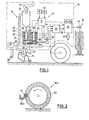
- a road spreader 12 in the form of a salt spreader and a control device 13 therefor are attached to a vehicle 11.
- the control device has in the illustrated Ausdusun g s-for example a receptacle 14 in the form of a suction device, as is known commercial vacuum cleaners, or street cleansing vehicles. It has a suction head 15 and a device 16 for lifting and lowering.
- a separator tank 18 is connected, the z. B. can work in the manner of a cyclone and from which the separated liquid is fed via an outlet 19 to a measuring chamber 20, optionally via a dirt separator, not shown.
- the suction fan 21 of the suction device is connected to the separating tank 18.
- the measuring chamber 20 consists of an insulating block 22 in which two vertical, mutually parallel measuring chamber bores 23, 24 are provided at a distance from one another, which are crossed by a bore 25 in the lower region.
- the bore 25 is closed in the illustrated state by a cylindrical slide 26, so that the two measuring chamber bores 23, 24 are closed at the bottom.
- a groove is provided in its upper region in the wall separating the two measuring chamber bores 23, 24 from one another, and thus the two Connects the measuring chamber bores.
- a cleaning brush is arranged on the upper side of the slide 26 and passes through and cleans the groove 27 when the slide is pulled back.
- Relatively large tubular electrodes are used in the wall area in both measuring chamber bores, which, together with the relatively long and defined path through the electrolyte determined by the groove 27, enable a very good salt content measurement. More information on the design of this measuring chamber is described in DE-OS 29 14 158, to which reference is made.
- a temperature sensor 28 is also arranged in the measuring chamber and supplies a temperature value for compensating the temperature dependency of the salt concentration measurement.
- the liquid inlet 29 is provided on the measuring chamber bore 23.
- electrodes 30 are provided which give a pulse to a control unit 31 belonging to the quantity measuring device when the liquid has reached this outlet.
- the slide 26 can be retracted by a motor 32.
- the motor 32 can be operated from the control unit 31.
- the quantity measurement cycle begins either time-controlled via a timer 33 or manually via a switch 34.
- the suction head 15 is placed on the roadway with the device 16 and either simultaneously or with a certain delay of the slider 26 via the motor 32 closed.
- the amount of liquid sucked in depends on the defined width of the suction head 15, the amount of liquid on the road and the distance traveled per unit of time. Accordingly, liquid separated from the separating container will fill the measuring chamber 20 more or less quickly.
- the measuring chamber filling sensor in the form of electrodes 30 responds, the time elapsed up to that point is determined in control unit 31. This time is in a more or less linear inverse dependence on the liquid found on the road during this time unit.
- the absolute quantity in g or 1 per square meter of the road surface could be determined. It would also be possible, instead of a time measurement for the filling of the measuring chamber, to provide a path measurement which delivers this value directly.
- the salt concentration measurement is then carried out in a known manner, which takes place via the two large, tubular electrodes 35 and the measuring channel in the form of the groove 27.
- the measured value for the salt concentration obtained is compared in the control device 55 with the signal of a non-contact temperature measuring device 37 with an infrared sensor 36, which is directed towards the street, and gives on the output line 38 a difference in temperature value between the freezing point of the salt / water solution found and the present one Road temperature.
- the output line 38 is connected to a display and control unit 39, which also receives signals from the quantity control unit 31.
- the display and control device 39 has displays for the described freezing point differential temperature and the amount of liquid per unit time or area. Manual control of a spreader could be based on these initial values. respectively.
- the spreading device 12 which has a controllable drive or metering motor, is connected directly to the display and control device 39.
- the method of operation can now be set via a manually operated setting device 40.
- the display and control unit will sensibly be programmed so that scatter only begins below a certain threshold differential temperature between freezing point and ambient temperature. This threshold could, however, when a program with consideration of a come Eden precipitate as a function of the present on the road Salzmen still g e (determined from liquid quantity measurement, and salt concentration) to be different so that for example, at locations less with little liquid salt concentration already above a per se precautionary re-salting is carried out in order to have safe values for precipitation to be expected at night.
- the spreader is put into operation and the spread rate is adjusted depending on all measured values so that there is a salt concentration on all road sections that is just sufficient to prevent ice formation at the present or expected ambient temperature .
- an expected precipitation can be taken into account by manual intervention or appropriate programming of the control unit.
- the suction head 15 can be lifted off the road again and, after the salinity measurement has been carried out, the slide valve 26 is opened via the motor 32 in order to empty the measuring chamber again and thus also to clean it.
- the measurement process is repeated automatically or manually from time to time via the timer 32 or the manual switch 34.
- the liquid quantity measurement can also be carried out purely as a function of time. However, if you want an ad that also Regulation of the quantity of spreading material from other spreading vehicles is to be used, or if a speed-dependent metering spreader is used, this measured value can be delivered by a tachometer unit 42 driven by the vehicle wheels delivering a corresponding measurement signal to the control unit 31 which is speed-dependent or distance-dependent.
- the measuring device shown measures with a constant measured quantity and variable time or distance. However, it is also possible to work with a constant time or distance, for example by placing the suction head 15 on the road for a certain time or distance and measuring the amount of liquid taken up in the process.
- a correction device (not shown here) should be provided, which takes into account the effect of different driving speeds and / or different amounts of liquid on the measurement result with empirically determined correction variables.
- the measurement result can also be recorded with a recorder for documentation and better clarity.
- FIG. 2 shows a sensor 14a which consists of a measuring wheel which can be raised and lowered on a vehicle and has a defined width on a foam pad 50 which is capable of absorbing road moisture when the sensor is on the roadway is lowered.
- the moisture absorbed therein is expressed by means of one or more squeeze rollers 51 and fed to the quantity measuring device via a liquid inlet 29a.
- This sensor 14a would therefore replace the suction device 14. Otherwise, the device can operate as described with reference to FIG. 1.
- the control can immediately access and set the respectively current values on the spreading device within the time difference generated by the driving speed.
Landscapes
- Physics & Mathematics (AREA)
- General Physics & Mathematics (AREA)
- Engineering & Computer Science (AREA)
- Architecture (AREA)
- Civil Engineering (AREA)
- Structural Engineering (AREA)
- Road Repair (AREA)
- Investigating Or Analyzing Materials By The Use Of Electric Means (AREA)
- Compounds Of Alkaline-Earth Elements, Aluminum Or Rare-Earth Metals (AREA)
- Materials Applied To Surfaces To Minimize Adherence Of Mist Or Water (AREA)
Priority Applications (1)
| Application Number | Priority Date | Filing Date | Title |
|---|---|---|---|
| AT83110671T ATE37450T1 (de) | 1982-11-09 | 1983-10-26 | Einrichtung zur regelung einer strassenstreuvorrichtung fuer salz o.dgl. |
Applications Claiming Priority (2)
| Application Number | Priority Date | Filing Date | Title |
|---|---|---|---|
| DE3241285A DE3241285C1 (de) | 1982-11-09 | 1982-11-09 | Einrichtung zur Regelung einer Strassen-Streuvorrichtung fuer Salz o.dgl. |
| DE3241285 | 1982-11-09 |
Publications (3)
| Publication Number | Publication Date |
|---|---|
| EP0108337A2 true EP0108337A2 (fr) | 1984-05-16 |
| EP0108337A3 EP0108337A3 (en) | 1985-08-21 |
| EP0108337B1 EP0108337B1 (fr) | 1988-09-21 |
Family
ID=6177634
Family Applications (1)
| Application Number | Title | Priority Date | Filing Date |
|---|---|---|---|
| EP83110671A Expired EP0108337B1 (fr) | 1982-11-09 | 1983-10-26 | Dispositif pour le sablage de routes |
Country Status (4)
| Country | Link |
|---|---|
| US (1) | US4577781A (fr) |
| EP (1) | EP0108337B1 (fr) |
| AT (1) | ATE37450T1 (fr) |
| DE (1) | DE3241285C1 (fr) |
Cited By (2)
| Publication number | Priority date | Publication date | Assignee | Title |
|---|---|---|---|---|
| EP0815546A4 (fr) * | 1995-03-21 | 2000-05-24 | Sprague Controls Inc | Indicateur de givrage imminent |
| US20220064886A1 (en) * | 2019-05-28 | 2022-03-03 | Ari J. Ostrow | Robotic de-icer |
Families Citing this family (21)
| Publication number | Priority date | Publication date | Assignee | Title |
|---|---|---|---|---|
| US6166657A (en) * | 1995-03-21 | 2000-12-26 | Commercial Vehicle Systems, Inc. | Imminent icing condition enunciator |
| US6938829B2 (en) * | 1996-06-07 | 2005-09-06 | John A. Doherty | Apparatus and system for synchronized application of one or more materials to a surface from a vehicle and control of a vehicle mounted variable position snow removal device |
| US6535141B1 (en) * | 1996-06-07 | 2003-03-18 | John A. Doherty | Vehicle mounted travel surface and weather condition monitoring system |
| US7839301B2 (en) * | 1995-06-08 | 2010-11-23 | Western Strategic Products, Llc | Surface condition sensing and treatment systems, and associated methods |
| US7400267B1 (en) | 1995-06-08 | 2008-07-15 | Western Strategic Products, Llc | Methods for determining need for treating a vehicle travel surface |
| US5603452A (en) * | 1995-08-31 | 1997-02-18 | Hester; Harvey L. | Stationary spreader |
| DE19547968C2 (de) * | 1995-12-22 | 1998-12-03 | Schmidt Holding Europ Gmbh | Verfahren und Vorrichtung zur Messung der Konzentration von Tausalzen auf Fahrbahnen |
| US6113310A (en) * | 1997-06-20 | 2000-09-05 | Hesse, Jr.; Ronald | Road repair apparatus and method for pavement patching |
| US6206299B1 (en) * | 1998-04-17 | 2001-03-27 | Commercial Vehicle Systems, Inc. | Traction enhancing deployment system |
| US6347753B1 (en) | 2000-03-21 | 2002-02-19 | Case Corporation | Zero velocity spreading system for distributing particulate material |
| US7355509B2 (en) | 2005-02-25 | 2008-04-08 | Iwapi Inc. | Smart modem device for vehicular and roadside applications |
| US9601015B2 (en) | 2005-02-25 | 2017-03-21 | Concaten, Inc. | Maintenance decision support system and method for vehicular and roadside applications |
| US8275522B1 (en) | 2007-06-29 | 2012-09-25 | Concaten, Inc. | Information delivery and maintenance system for dynamically generated and updated data pertaining to road maintenance vehicles and other related information |
| US9864957B2 (en) | 2007-06-29 | 2018-01-09 | Concaten, Inc. | Information delivery and maintenance system for dynamically generated and updated data pertaining to road maintenance vehicles and other related information |
| US8231270B2 (en) * | 2008-01-03 | 2012-07-31 | Concaten, Inc. | Integrated rail efficiency and safety support system |
| FR2957666B1 (fr) | 2010-03-16 | 2012-06-01 | Michelin Soc Tech | Dispositif de mesure de la temperature de l'eau revetant une chaussee |
| US8902081B2 (en) | 2010-06-02 | 2014-12-02 | Concaten, Inc. | Distributed maintenance decision and support system and method |
| EP2769022A4 (fr) * | 2011-10-05 | 2015-07-01 | Roger Vanderlinden | Appareil destiné à être utilisé comme partie d'un véhicule de nettoyage de surface et comme partie d'un véhicule de sablage-salage |
| ITTO20121153A1 (it) * | 2012-12-27 | 2014-06-28 | Febo S R L | Metodo e dispositivo di misura per determinare la salinita' su un manto stradale, e veicolo provvisto di tale dispositivo di misura |
| JP7234231B2 (ja) * | 2017-11-10 | 2023-03-07 | イーグル エアロスペース,リミテッド | 空港除氷化学薬品を散布、回収およびリサイクルする方法およびシステム |
| CN118072497B (zh) * | 2024-04-25 | 2024-08-13 | 华睿交通科技股份有限公司 | 一种基于远程通信的道路险情预警系统 |
Family Cites Families (4)
| Publication number | Priority date | Publication date | Assignee | Title |
|---|---|---|---|---|
| DE1936564C3 (de) * | 1969-07-18 | 1974-05-02 | Hubert Weisser Kg, 7715 Braeunlingen | Auf Streufahrzeuge aufsetzbares Streugerät |
| DE2648906C3 (de) * | 1976-10-28 | 1980-11-06 | Otto Peter Ing.(Grad.) 7141 Freiberg Braun | Gerät zur Feststellung von Glatteisgefahr auf Straßen |
| SE7804068L (sv) * | 1978-04-11 | 1979-10-12 | Braun Otto P | Anordning for att faststella risk for ishalka pa en vegbana |
| EP0006272B1 (fr) * | 1978-06-21 | 1982-01-06 | SOLVAY & Cie (Société Anonyme) | Procédé et dispositif pour contrôler le dosage d'un fondant chimique sur une route |
-
1982
- 1982-11-09 DE DE3241285A patent/DE3241285C1/de not_active Expired
-
1983
- 1983-10-26 AT AT83110671T patent/ATE37450T1/de not_active IP Right Cessation
- 1983-10-26 EP EP83110671A patent/EP0108337B1/fr not_active Expired
- 1983-11-08 US US06/549,775 patent/US4577781A/en not_active Expired - Fee Related
Cited By (3)
| Publication number | Priority date | Publication date | Assignee | Title |
|---|---|---|---|---|
| EP0815546A4 (fr) * | 1995-03-21 | 2000-05-24 | Sprague Controls Inc | Indicateur de givrage imminent |
| US20220064886A1 (en) * | 2019-05-28 | 2022-03-03 | Ari J. Ostrow | Robotic de-icer |
| US11933008B2 (en) * | 2019-05-28 | 2024-03-19 | Ari J. Ostrow | Robotic de-icer |
Also Published As
| Publication number | Publication date |
|---|---|
| DE3241285C1 (de) | 1984-07-12 |
| ATE37450T1 (de) | 1988-10-15 |
| US4577781A (en) | 1986-03-25 |
| EP0108337A3 (en) | 1985-08-21 |
| EP0108337B1 (fr) | 1988-09-21 |
Similar Documents
| Publication | Publication Date | Title |
|---|---|---|
| EP0108337B1 (fr) | Dispositif pour le sablage de routes | |
| DE3441893C2 (fr) | ||
| DE3310424C2 (de) | Vorrichtung zum Ausbringen von Schüttgut, wie Dünger, Saatgut od.dgl. | |
| DE9402324U1 (de) | Straßenfertiger | |
| EP1797401B1 (fr) | Systeme et procede servant a mesurer des quantites de lait, en particulier pendant le processus de traite | |
| DE69802857T2 (de) | Vorrichtung, Verfahren und Steuerungsvorrichtung zum Dosieren von Waschmittel | |
| DE2944869A1 (de) | Geraet zum automatischen abmessen und dosieren von fluessigkeiten, insbesondere farben | |
| DE2648906C3 (de) | Gerät zur Feststellung von Glatteisgefahr auf Straßen | |
| DE1583773A1 (de) | Steuervorrichtung fuer schnell laufende magnetische Trommel-Separatoren | |
| DE69001400T2 (de) | Verfahren zur automatischen Steuerung einer diskontinuierlich angetriebenen Zentrifuge. | |
| EP0828120A1 (fr) | Dispositif pour délivrer des quantités dosées de glaçons | |
| DE2745310A1 (de) | Verfahren und vorrichtung zur messung der durchlaessigkeit von filtermitteln | |
| DE1507887A1 (de) | Verfahren und Vorrichtung zum Herstellen eines bestimmten Mischungsverhaeltnisses verschiedener Komponenten | |
| DE2914158C2 (fr) | ||
| DE2438575A1 (de) | Drillenkontrolle | |
| EP0119292B1 (fr) | Procédé de réglage de l'apport de produits agricoles sur une surface | |
| DE1964273B2 (de) | Verfahren und Vorrichtung zur Steuerung des Wärmeübergangs an einen länglichen Körper | |
| DE19604753C1 (de) | Fahrzeug und Verfahren zur Ausbringung von Klärschlammfrischmasse oder anderen organischen Düngemitteln | |
| DE69618120T2 (de) | Verfahren zur Bestimmung der während des Melkens abgegebenen Milchmengen | |
| DE3443360C2 (de) | Sämaschine | |
| EP2220927B1 (fr) | Appareil de jardinage pour l'entretien de la pelouse | |
| DE2132037C3 (de) | Selbsttätig steuerbarer Seilschrapper | |
| DE102010055153B4 (de) | Vorrichtung zur Bestimmung des Fließverhaltens von mit einem Düngerstreuer auszubringendem Düngemittel | |
| DE1925370A1 (de) | Vorrichtung zum Streuen von pulverigem oder koernigem Streugut | |
| DE2043830C3 (de) | Einrichtung zum Ausbringen von Streugut |
Legal Events
| Date | Code | Title | Description |
|---|---|---|---|
| PUAI | Public reference made under article 153(3) epc to a published international application that has entered the european phase |
Free format text: ORIGINAL CODE: 0009012 |
|
| AK | Designated contracting states |
Designated state(s): AT CH FR GB LI |
|
| PUAL | Search report despatched |
Free format text: ORIGINAL CODE: 0009013 |
|
| AK | Designated contracting states |
Designated state(s): AT CH FR GB LI |
|
| 17P | Request for examination filed |
Effective date: 19860211 |
|
| 17Q | First examination report despatched |
Effective date: 19871013 |
|
| GRAA | (expected) grant |
Free format text: ORIGINAL CODE: 0009210 |
|
| RAP1 | Party data changed (applicant data changed or rights of an application transferred) |
Owner name: HUBERT WEISSER KG |
|
| AK | Designated contracting states |
Kind code of ref document: B1 Designated state(s): AT CH FR GB LI |
|
| REF | Corresponds to: |
Ref document number: 37450 Country of ref document: AT Date of ref document: 19881015 Kind code of ref document: T |
|
| ET | Fr: translation filed | ||
| GBT | Gb: translation of ep patent filed (gb section 77(6)(a)/1977) | ||
| PLBE | No opposition filed within time limit |
Free format text: ORIGINAL CODE: 0009261 |
|
| STAA | Information on the status of an ep patent application or granted ep patent |
Free format text: STATUS: NO OPPOSITION FILED WITHIN TIME LIMIT |
|
| 26N | No opposition filed | ||
| REG | Reference to a national code |
Ref country code: GB Ref legal event code: IF02 |
|
| PGFP | Annual fee paid to national office [announced via postgrant information from national office to epo] |
Ref country code: AT Payment date: 20020912 Year of fee payment: 20 |
|
| PGFP | Annual fee paid to national office [announced via postgrant information from national office to epo] |
Ref country code: FR Payment date: 20020927 Year of fee payment: 20 |
|
| PGFP | Annual fee paid to national office [announced via postgrant information from national office to epo] |
Ref country code: GB Payment date: 20021008 Year of fee payment: 20 |
|
| PGFP | Annual fee paid to national office [announced via postgrant information from national office to epo] |
Ref country code: CH Payment date: 20021010 Year of fee payment: 20 |
|
| PG25 | Lapsed in a contracting state [announced via postgrant information from national office to epo] |
Ref country code: LI Free format text: LAPSE BECAUSE OF EXPIRATION OF PROTECTION Effective date: 20031025 Ref country code: GB Free format text: LAPSE BECAUSE OF EXPIRATION OF PROTECTION Effective date: 20031025 Ref country code: CH Free format text: LAPSE BECAUSE OF EXPIRATION OF PROTECTION Effective date: 20031025 |
|
| PG25 | Lapsed in a contracting state [announced via postgrant information from national office to epo] |
Ref country code: AT Free format text: LAPSE BECAUSE OF EXPIRATION OF PROTECTION Effective date: 20031026 |
|
| REG | Reference to a national code |
Ref country code: CH Ref legal event code: PL |
|
| REG | Reference to a national code |
Ref country code: GB Ref legal event code: PE20 |