EP0108361A1 - Vormischbrenner mit integriertem Diffusionsbrenner - Google Patents
Vormischbrenner mit integriertem Diffusionsbrenner Download PDFInfo
- Publication number
- EP0108361A1 EP0108361A1 EP83110824A EP83110824A EP0108361A1 EP 0108361 A1 EP0108361 A1 EP 0108361A1 EP 83110824 A EP83110824 A EP 83110824A EP 83110824 A EP83110824 A EP 83110824A EP 0108361 A1 EP0108361 A1 EP 0108361A1
- Authority
- EP
- European Patent Office
- Prior art keywords
- burner
- fuel
- premix
- diffusion
- fuel nozzle
- Prior art date
- Legal status (The legal status is an assumption and is not a legal conclusion. Google has not performed a legal analysis and makes no representation as to the accuracy of the status listed.)
- Granted
Links
- 238000009792 diffusion process Methods 0.000 title claims abstract description 69
- 239000000446 fuel Substances 0.000 claims abstract description 194
- 238000002485 combustion reaction Methods 0.000 claims abstract description 59
- 239000007788 liquid Substances 0.000 claims description 21
- 238000002347 injection Methods 0.000 claims description 6
- 239000007924 injection Substances 0.000 claims description 6
- 238000011144 upstream manufacturing Methods 0.000 claims description 3
- 230000010354 integration Effects 0.000 abstract description 2
- 239000007789 gas Substances 0.000 description 43
- 230000015572 biosynthetic process Effects 0.000 description 6
- 230000008020 evaporation Effects 0.000 description 4
- 238000001704 evaporation Methods 0.000 description 4
- 238000010586 diagram Methods 0.000 description 3
- MWUXSHHQAYIFBG-UHFFFAOYSA-N nitrogen oxide Inorganic materials O=[N] MWUXSHHQAYIFBG-UHFFFAOYSA-N 0.000 description 3
- 238000000889 atomisation Methods 0.000 description 2
- 239000002828 fuel tank Substances 0.000 description 2
- 238000007689 inspection Methods 0.000 description 2
- 238000012423 maintenance Methods 0.000 description 2
- 239000000203 mixture Substances 0.000 description 2
- 230000001105 regulatory effect Effects 0.000 description 2
- 238000010399 three-hybrid screening Methods 0.000 description 2
- 230000001419 dependent effect Effects 0.000 description 1
- 230000007613 environmental effect Effects 0.000 description 1
- 239000003344 environmental pollutant Substances 0.000 description 1
- 239000008240 homogeneous mixture Substances 0.000 description 1
- 231100000719 pollutant Toxicity 0.000 description 1
- 239000007787 solid Substances 0.000 description 1
Images


Classifications
-
- F—MECHANICAL ENGINEERING; LIGHTING; HEATING; WEAPONS; BLASTING
- F23—COMBUSTION APPARATUS; COMBUSTION PROCESSES
- F23R—GENERATING COMBUSTION PRODUCTS OF HIGH PRESSURE OR HIGH VELOCITY, e.g. GAS-TURBINE COMBUSTION CHAMBERS
- F23R3/00—Continuous combustion chambers using liquid or gaseous fuel
- F23R3/28—Continuous combustion chambers using liquid or gaseous fuel characterised by the fuel supply
- F23R3/36—Supply of different fuels
-
- F—MECHANICAL ENGINEERING; LIGHTING; HEATING; WEAPONS; BLASTING
- F23—COMBUSTION APPARATUS; COMBUSTION PROCESSES
- F23D—BURNERS
- F23D11/00—Burners using a direct spraying action of liquid droplets or vaporised liquid into the combustion space
- F23D11/005—Burners using a direct spraying action of liquid droplets or vaporised liquid into the combustion space with combinations of different spraying or vaporising means
-
- F—MECHANICAL ENGINEERING; LIGHTING; HEATING; WEAPONS; BLASTING
- F23—COMBUSTION APPARATUS; COMBUSTION PROCESSES
- F23D—BURNERS
- F23D23/00—Assemblies of two or more burners
-
- F—MECHANICAL ENGINEERING; LIGHTING; HEATING; WEAPONS; BLASTING
- F23—COMBUSTION APPARATUS; COMBUSTION PROCESSES
- F23R—GENERATING COMBUSTION PRODUCTS OF HIGH PRESSURE OR HIGH VELOCITY, e.g. GAS-TURBINE COMBUSTION CHAMBERS
- F23R3/00—Continuous combustion chambers using liquid or gaseous fuel
- F23R3/28—Continuous combustion chambers using liquid or gaseous fuel characterised by the fuel supply
- F23R3/286—Continuous combustion chambers using liquid or gaseous fuel characterised by the fuel supply having fuel-air premixing devices
-
- F—MECHANICAL ENGINEERING; LIGHTING; HEATING; WEAPONS; BLASTING
- F23—COMBUSTION APPARATUS; COMBUSTION PROCESSES
- F23D—BURNERS
- F23D2900/00—Special features of, or arrangements for burners using fluid fuels or solid fuels suspended in a carrier gas
- F23D2900/00008—Burner assemblies with diffusion and premix modes, i.e. dual mode burners
Definitions
- the invention relates to a premix burner with an integrated diffusion burner for gas turbine combustion chambers according to the preamble of claim 1.
- NO x When gaseous or liquid fuels are burned in gas turbine combustion chambers, the nitrogen oxides NO and N0 2 , which are collectively referred to as NO x , are formed as pollutants in the exhaust gas.
- the NO x content in the exhaust gas is to be kept as low as possible, for example in the USA due to environmental protection regulations a limit value of 75 ppm at 15% by volume 0 2 must not be exceeded. Compliance with these regulations is particularly difficult when conventional diffusion burners are used in the gas turbine combustion chambers. In such diffusion burners, the fuel is introduced directly into the combustion zone via a fuel nozzle and mixed there with the combustion air, the combustion being controlled by turbulent diffusion processes between the fuel, the combustion air and the exhaust gas products. Since there are large temperature differences with high temperature peaks due to the locally different mixing ratios of fuel and combustion air during combustion, there is a relatively high NO x content in the exhaust gas.
- premix burners for gas turbine combustion chambers, in whose premixing chambers the premixing and pre-evaporation of the liquid fuel supplied by fuel nozzles and / or the premixing of the gaseous fuel supplied by fuel nozzles with the combustion air takes place with a large excess of air .
- Vor-Klk 2 Fl / 29.10.1982 Mixing means that locally different mixing ratios of fuel and combustion air are avoided during combustion.
- premix burners of this type have a much smaller working range than conventional diffusion burners, ie the mixing ratios of fuel and combustion air must be kept within relatively narrow limits.
- the fuel lines of the individual premix burners are therefore equipped with valves so that, depending on the load of the gas turbine, only so many premix burners are supplied with fuel for the operation of which the narrow limits of the mixing ratios can be maintained.
- some conventional diffusion burners are also provided, which are only used to start the gas turbine and are then switched off again.
- the premix burner has a premixing chamber delimited at the downstream end by a flame holder, into which a main fuel nozzle and a feed device for combustion air open.
- the diffusion burner has a pilot fuel nozzle arranged in the central area of the flame holder, the combustion air for the operation of the diffusion burner being supplied partly through the premixing chamber of the premixing burner and partly through holes arranged in the flame tube of the gas turbine combustion chamber.
- a fuel control device which controls the total amount and the partial amounts of the fuel supplied to the main fuel nozzle and the pilot fuel nozzle, depending on the load of the gas turbine, in such a way that until idling speed or a low is reached only the diffusion burner can be operated against partial load and then the diffusion burner and the premix burner can be operated together.
- Such hybrid burners therefore have the advantage that separate start-up burners designed as diffusion burners can be dispensed with in a space-saving, compact design.
- the flame of the diffusion burner supports the combustion of the mixture of fuel and combustion air generated in the premixing chamber, ie the flame of the premix burner can be ignited even with extremely lean mixture ratios with regard to low NO x formation.
- the hybrid burner can thus be operated over a wide load range with a low NO content in the exhaust gas, although an undesirable increase in the formation of NO x can be observed in the upper load range and in particular under limit load.
- the invention has for its object to provide a premix burner with an integrated diffusion burner for gas turbine combustion chambers, which enables operation with low NO x formation over the entire load range.
- the invention is based on the knowledge that when the premix burner is operated solely in the upper load range, the NO formation can be significantly reduced and that the premix burner can only be operated in the upper load range if the total combustion air available is exclusively via the premixing chamber is fed.
- the fuel control device reduces the partial amount of fuel supplied to the pilot fuel nozzle with increasing load from reaching the idle speed or a low partial load.
- the NO formation caused by the operation of the diffusion burner is then reduced more than the NO formation additionally caused by the operation of the premix burner with a correspondingly increased amount of fuel, the support of the flame of the premix burner by the flame of the diffusion burner, however, being fully guaranteed.
- the fuel control device can also be assigned to further premix burners with integrated diffusion burners, as a result of which, in particular, the overall effort required for valves in a gas turbine combustion chamber can be significantly reduced.
- the premix burner has a first main fuel nozzle for gaseous fuel and a second main fuel nozzle for liquid fuel.
- the diffusion burner can then also have a first pilot fuel nozzle for gaseous fuel and a second pilot fuel nozzle for liquid fuel.
- the integration of the diffusion burner into the premix burner can be accomplished with particularly little effort in that the fuel feed line to the pilot fuel nozzle passes through the premix chamber centrally and in the axial direction. If the diffusion burner can be operated with gaseous and / or liquid fuel, it is correspondingly provided that the fuel feed lines to the first pilot fuel nozzle and the second pilot fuel nozzle penetrate the premixing chamber centrally and in the axial direction as concentric tubes.
- premix burner can also be operated with gaseous and / or liquid fuel, a particularly compact design can be achieved in that the fuel feed lines to the two main fuel nozzles and the two pilot fuel nozzles are designed as concentric tubes.
- the feed device for combustion air opening into the premixing chamber is designed as a swirl device. This further promotes the intensive mixing of combustion air and fuel in the premixing chamber.
- the swirl device can then also be designed simultaneously as a main fuel nozzle, with several fuel injection bores being made in each case in vanes designed as hollow blades.
- a particularly intensive atomization and pre-evaporation of liquid fuel in the combustion air can also be achieved in that the premixing chamber has a venturi-like contour with a section converging at the upstream end and a section diverging at the downstream end.
- both the premix burner and the diffusion burner can be operated with gaseous and / or liquid fuel
- the fuel feed lines, the main fuel nozzles and the two pilot fuel nozzles can be combined to form a component which can be pulled out of the premixing chamber in the axial direction.
- the hybrid burner 1 shows a highly simplified schematic illustration of a longitudinal section through a hybrid burner, designated overall by 1, which can be operated as a premix burner and / or diffusion burner.
- the hybrid burner 1 has a burner housing 10 which carries a flame holder 11 at one end and a swirl device 12 at its other end.
- a main fuel nozzle 13 is arranged in the central region of the swirl device 12, while the fuel feed line is designated by 14.
- a pilot fuel nozzle 15 is arranged in the central area of the flame holder 11, the fuel feed line 16 passing through the main fuel nozzle 13 and the burner housing 10 centrally and in the axial direction.
- the liquid indicated by an arrow HB arrives Main fuel from a fuel tank BT via a main fuel pump HBP and a main fuel control valve HBRV into the fuel feed line 14 of the main fuel nozzle 13.
- the main fuel HB then becomes the finely divided form in a premixing chamber 100 from the main fuel nozzle 13 injected, which is limited by the burner housing 10, the flame holder 11 and the swirl device 12.
- the main fuel HB is evaporated in this premixing chamber 100 and mixed with the combustion air VL supplied via the swirl device 12, this mixing and the pre-evaporation being favored by the venturi-like contour of the burner housing 10.
- the combustion of the homogeneous mixture of main fuel HB and combustion air VL formed in the premixing chamber 100 then takes place only in the flame tube F of a gas turbine combustion chamber, which is not shown in any more detail, the flame holder 11 serving to stabilize the flame, but nonetheless a flashback into the flame Pre-mixing chamber 100 prevented.
- the pilot fuel indicated by an arrow PB reaches the fuel feed line 16 of the pilot fuel nozzle 15 from the fuel tank BT via a pilot fuel pump PBP and a pilot fuel control valve PBRV.
- the pilot fuel PB is then injected in a finely divided form directly into the combustion zone of the flame tube F and mixed there with the combustion air VL supplied exclusively via the swirl device 12, the premixing chamber 100 and the flame holder 11, the combustion being effected by turbulent diffusion processes between the Pilot fuel PB, the combustion air VL and the exhaust products is controlled.
- the total amount of fuel supplied and that of the pilot fuel PB or partial quantities supplied as main fuel HB are regulated via a fuel control device BRE depending on the load of the gas turbine.
- the fuel control device BRE to which a corresponding load signal LS is applied, regulates the flow through the pilot fuel control valve PBRV and the main fuel control valve HBRV via corresponding control lines AL1 and AL2 such that only the diffusion burner until the idling speed or a low partial load is reached it can be operated that the diffusion burner and the premix burner can then be operated together and that only the premix burner can be operated in the upper load range.
- the flame tube F shown in FIG. 1 can be, for example, the flame tube of a primary combustion chamber, the gas turbine combustion chamber having a large number of such primary combustion chambers opening into a common mixing chamber.
- the fuel control device BRE, the pilot fuel control valve PBRV and the main fuel control valve HBRV can then be combined for all hybrid burners 1 of the gas turbine combustion chamber, since the large working range of the hybrid burner 1 means that separate control and a load-dependent switching on and off of individual primary combustion chambers can be omitted.
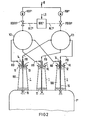
- Such a common fuel control device is also possible if a large number of hybrid burners open into the flame tube of a gas turbine combustion chamber. This case is shown in FIG. 2, but only three hybrid burners 1 are shown to simplify the drawing.
- FIG. 2 three hybrid burners 1 can be seen in FIG. 2, which open into the flame tube designated F 'of a gas turbine combustion chamber, which is otherwise not shown in detail.
- the flame tube F ' has no openings for the access of Ver in the area of the combustion zone combustion air, since the entire available combustion air VL is supplied exclusively to the mixing chambers 100 of the hybrid burner 1. However, this does not exclude that openings for the entry of mixed air may be present in the flame tube F 'downstream of the combustion zone. '
- the pilot fuel PB enters the fuel supply lines 16 to the pilot fuel nozzles 15 of the individual hybrid burners 1 via a common pilot fuel pump PBP ', a common pilot fuel control valve PBRV' and a distributor V1 shown as a circle.
- the main fuel HB reaches the main fuel nozzles 13 of the individual hybrid burners 1 via a common main fuel pump HBP ′, a common main fuel control valve HBRV ′ and a distributor V2 shown as a circle in the fuel feed lines 14.
- the total quantity of fuel B supplied to hybrid burners 1 and the partial quantities supplied overall as pilot fuel PB or as main fuel HB are regulated by a fuel control device BRE 'depending on the load of the gas turbine.
- the fuel control device BRE ' to which a corresponding load signal LS is applied, regulates the flow through the common pilot fuel control valve PBRV' and the common main fuel control valve HBRV 'via corresponding control lines Ah1' and AL2 'in such a way that until the idling speed is reached or a low partial load, only the diffusion burners can be operated, that thereafter the diffusion burners and the premix burners can be operated together and that only the premix burners can be operated in the upper load range.
- the above-described mode of operation is based on the 3 in even more detail.
- On the right branch of the abscissa are the power N of the gas turbine up to the limit load in percent
- On the left branch of the abscissa the speeds n up to idling speed in rpm and on the ordinate the fuel ? ff quantities m applied.
- the solid curve shows the total amount m G of the fuel B supplied (see FIG. 2), the dashed curve, the amount mp of the total pilot fuel PB supplied (see FIG. 2) and the dashed curve, the amount m H of the total main fuel HB supplied (see FIG. 2).
- the exclusive operation of the diffusion burners is continued for a short time after the idling speed has been reached until the premix burners are switched on at a low partial load and are supplied with an increasing amount m H of main fuel HB (cf. FIG. 2).
- the quantity mp of the pilot fuel PB fed to the diffusion burner is reduced.
- the diffusion burners are then switched off completely and only the premix burners are operated, ie only main fuel HB (see FIG. 2) is supplied.
- the upper load range in which the diffusion burners are switched off could also be defined as the range between the flame stability limit of the premix burner and the desired NO x limit at the limit load.
- the diffusion burners are only switched off when the premix burners are not supported by the flame of the diffusion burners can burn alone and without the danger of extinguishing.
- the diagram of FIG. 4 shows the NO x emission during operation of the gas turbine combustion chamber shown in FIG. 2.
- the NO x content in the exhaust gas in ppm at 15% by volume 0 2 is plotted on the ordinate.
- the straight line G running parallel to the abscissa indicates a NO x limit value of 75 ppm at 15% by volume 0 2 , which must not be exceeded during operation of the gas turbine combustion chamber.
- the hybrid burners 1 When starting the gas turbine combustion chamber shown in FIG. 2, the hybrid burners 1 are operated exclusively as a diffusion burner until a low partial load is reached, the NO x content in the exhaust gas being indicated by the point A on the curve D during this operating phase. Thereafter, the hybrid burners 1 are operated as a diffusion burner and at the same time as a premix burner, the NO x content in the exhaust gas during this Operating phase is indicated by the thick curve AB.
- the last vertical section of curve AB illustrates the drop in the NO x content in the exhaust gas after the diffusion burner has been completely switched off. Accordingly, the point B lies above the flame stability limit S v on the curve V. After the diffusion burners have been switched off, the hybrid burners 1 are then operated in the upper load range exclusively as a premix burner.
- Point C corresponds to the maximum value of the NO x content in the exhaust gas reached at the limit load, although this maximum value is still significantly below the permissible NO x limit G. Point C is therefore also the design point of the gas turbine combustion chamber, which is decisive for the total number of hybrid burners 1 required.
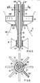
- the hybrid burner which can be operated with gaseous and / or liquid fuel in the longitudinal section or in cross section which is only partially shown.
- the hybrid burner designated overall by 1 ', has a burner housing which is indicated by the broken line 10' and which has a venturi-like contour.
- the premixing chamber 100 'formed by the burner housing 10' is delimited at its downstream end by a flame holder 11 'only indicated in the drawing and at its upstream end by a swirl device 12'.
- the swirl device 12 'simultaneously forms a first main fuel nozzle for gaseous fuel, a plurality of fuel injection bores 120' being made in each of the individual vanes designed as hollow blades.
- the gaseous fuel indicated by an arrow HB " is supplied via a fuel feed line 14" onto which the vanes designed as hollow blades are located the swirl device 12 'are placed.
- a second main fuel nozzle 13 'for liquid fuel is arranged at a short distance downstream of the swirl device 12' and also has vanes in the form of hollow blades, into each of which a plurality of fuel injection bores 130 'are made.
- the supply of the liquid fuel indicated by arrows HB 'to the fuel injection bores 130' takes place via a fuel feed line 14 ', which is arranged concentrically within the fuel feed line 14 "and on which the vanes of the second main fuel nozzle 13', which are designed as hollow blades, are placed .
- a first pilot fuel nozzle 15 "for gaseous fuel and a second pilot fuel nozzle 15 'for liquid fuel are arranged in the central region of the flame holder 11'.
- the supply of the gaseous fuel indicated by an arrow PB" to the first pilot fuel nozzle 15 " takes place via a fuel feed line 16 ′′, which initially runs concentrically within the fuel feed line 14 ′ and then passes through the premixing chamber 100 ′ centrally and in the axial direction.
- the liquid fuel, indicated by an arrow PB ', is supplied to the second pilot fuel nozzle 15' via a fuel feed line 16 ', which is arranged concentrically within the fuel feed line 16 ".
- the four fuel feed lines 14 ′′, 14 ′, 16 ′′, 16 ′, the swirl device 12 ′ that is simultaneously designed as the first main fuel nozzle, the second main fuel nozzle 13 ′, the first pilot fuel nozzle 15 ′′ and the second pilot fuel nozzle 15 ′ are combined into one component which can be pulled out of the burner housing 10 'and the flame holder 11' in the axial direction to facilitate maintenance and inspection.
- the operation of the hybrid burner 1 'shown in FIGS. 5 and 6 corresponds to the operation of the hybrid burner 1 shown in FIGS. 1 and 2, but for the liquid fuels PB' and HB 'and for the gaseous fuels PB "and HB"
- a fuel control device is provided in each case. If the hybrid burner 1 'is to be operated simultaneously with liquid and gaseous fuel, these two fuel control devices are to be linked to one another in accordance with the operating mode shown in FIG. 3.
Landscapes
- Engineering & Computer Science (AREA)
- Chemical & Material Sciences (AREA)
- Combustion & Propulsion (AREA)
- Mechanical Engineering (AREA)
- General Engineering & Computer Science (AREA)
Abstract
Description
- Die Erfindung betrifft einen Vormischbrenner mit integriertem Diffusionsbrenner für Gasturbinenbrennkammern nach dem Oberbegriff des Anspruchs 1.
- Bei der Verbrennung gasförmiger oder flüssiger Brennstoffe in Gasturbinenbrennkammern entstehen als Schadstoffe im Abgas u. a. die Stickstoffoxide NO und N02, die zusammengefaßt als NOx bezeichnet werden. Der NOX-Gehalt im Abgas ist möglichst gering zu halten, wobei beispielsweise in den USA aufgrund von Umweltschutzvorschriften ein Grenzwert von 75 ppm bei 15 Vol.-% 02 nicht überschritten werden darf. Die Einhaltung dieser Vorschriften bereitet insbesondere dann große Schwierigkeiten, wenn in den Gasturbinenbrennkammern konventionelle Diffusionsbrenner eingesetzt werden. Bei derartigen Diffusionsbrennern wird der Brennstoff über eine Brennstoffdüse direkt in die Verbrennungszone eingebracht und dort mit der Verbrennungsluft vermischt, wobei die Verbrennung durch turbulente Diffusionsvorgänge zwischen dem Brennstoff, der Verbrennungsluft und den Abgasprodukten gesteuert wird. Da durch örtlich unterschiedliche Mischungsverhältnisse von Brennstoff und Verbrennungsluft bei der Verbrennung starke Temperaturunterschiede mit hohen Temperaturspitzen entstehen, ergibt sich ein relativ hoher NOX-Gehalt im Abgas.
- Aus der DE-OS 29 50 535 ist es auch bekannt, für Gasturbinenbrennkammern sogenannte Vormischbrenner einzusetzen, in deren Vormischkammern das Vormischen und Vorverdampfen des durch Brennstoffdüsen zugeführten flüssigen Brennstoffes und/oder das Vormischen des durch Brennstoffdüsen zugeführten gasförmigen Brennstoffes mit der Verbrennungsluft bei großer Luftüberschußzahl abläuft. Durch das Vor-Klk 2 Fl/29.10.1982 mischen werden bei der Verbrennung also örtlich unterschiedliche Mischungsverhältnisse von Brennstoff und Verbrennungsluft vermieden. Andererseits besitzen/derartige Vormischbrenner einen wesentlich geringeren Arbeitsbereich als die konventionellen Diffusionsbrenner, d. h. die Mischungsverhältnisse von Brennstoff und Verbrennungsluft müssen in relativ engen Grenzen gehalten werden. Ist der Brennstoffanteil zu hoch, so wird zu viel NO x gebildet und ist zu wenig Brennstoff vorhanden, so erlischt die Verbrennung. Die Brennstoffleitungen der einzelnen Vormischbrenner werden daher mit Ventilen ausgerüstet, so daß in Abhängigkeit von der Last der Gasturbine jeweils nur so viele Vormischbrenner mit Brennstoff versorgt werden, für deren Betrieb die engen Grenzen der Mischungsverhältnisse eingehalten werden können. Außerdem sind zusätzlich noch einige konventionelle Diffusionsbrenner vorgesehen, die nur zum Anfahren der Gasturbine dienen und danach wieder abgeschaltet werden.
- Aus der DE-OS 26 13 589 sind auch bereits Hybridbrenner für Gasturbinenbrennkammern bekannt, welche aus Vormischbrennern mit integrierten Diffusionsbrennern bestehen. Der Vormischbrenner besitzt eine am stromabwärtigen Ende durch einen Flammenhalter begrenzte Vormischkammer, in welche eine Haupt-Brennstoffdüse und eine Zufuhreinrichtung für Verbrennungsluft einmünden. Der Diffusionsbrenner besitzt eine im zentralen Bereich des Flammenhalters angeordnete Pilot-Brennstoffdüse, wobei die Verbrennungsluft für den Betrieb des Diffusionsbrenners zum Teil durch die Vormischkammer des Vormischbrenners und zum Teil durch im Flammrohr der Gasturbinenbrennkammer angeordnete Löcher zugeführt wird. Zusätzlich ist eine Brennstoffregeleinrichtung vorgesehen, welche die Gesamtmenge und die Teilmengen des der Haupt-Brennstoffdüse und der Pilot-Brennstoffdüse zugeführten Brennstoffes in Abhängigkeit von der Last der Gasturbine derart regelt, daß bis zum Erreichen der Leerlaufdrehzahl oder einer geringen Teillast ausschließlich der Diffusionsbrenner betreibbar ist und danach der Diffusionsbrenner und der Vormischbrenner gemeinsam betreibbar sind. Derartige Hybridbrenner haben also den Vorteil, daß bei raumsparender kompakter Bauweise als Diffusionsbrenner ausgebildete separate Anfahrbrenner entfallen können. Außerdem stützt die Flamme des Diffusionsbrenners die Verbrennung des in der Vormischkammer erzeugten Gemisches aus Brennstoff und Verbrennungsluft, d. h. die Flamme des Vormischbrenners kann auch noch bei im Hinblick auf eine geringe NOx-Bildung extrem mageren Mischungsverhältnissen sicher zur Entzündung gebracht werden. Der Hybridbrenner kann also über einen weiten Lastbereich mit einem geringen NO-Gehalt im Abgas betrieben werden, wobei jedoch im oberen Lastbereich und insbesondere bei Grenzlast ein unerwünschter Anstieg der NOX-Bildung zu verzeichnen ist.
- Der Erfindung liegt die Aufgabe zugrunde, einen Vormischbrenner mit integriertem Diffusionsbrenner für Gasturbinenbrennkammern zu schaffen, welcher über den gesamten Lastbereich einen Betrieb mit geringer NOX-Bildung ermöglicht.
- Diese Aufgabe wird bei einer gattungsgemäßen Einrichtung durch die kennzeichnenden Merkmale des Anspruchs 1 gelöst.
- Der Erfindung liegt die Erkenntnis zugrunde, daß bei einem im oberen Lastbereich alleinigen Betrieb des Vormischbrenners die NO -Bildung wesentlich verringert werden kann und daß der alleinige Betrieb des Vormischbrenners im oberen Lastbereich aber nur dann möglich ist, wenn die gesamte zur Verfügung stehende Verbrennungsluft ausschließlich über die Vormischkammer zugeführt wird.
- Nach einer weiteren Ausbildung der Erfindung ist vorgesehen, daß die Brennstoffregeleinrichtung ab Erreichen der Leerlaufdrehzahl oder einer geringen Teillast die Teilmenge des der Pilot-Brennstoffdüse zugeführten Brennstoffes mit zunehmender Last verringert. Die durch den Betrieb des Diffusionsbrenners verursachte NO-Bildung wird dann stärker verringert, als die durch den Betrieb des Vormischbrenners mit entsprechend vergrößerter Brennstoffmenge zusätzlich verursachte NO-Bildung, wobei die Stützung der Flamme des Vormischbrenners durch die Flamme des Diffusionsbrenners jedoch voll gewährleistet ist.
- Die Brennstoffregeleinrichtung kann auch weiteren Vormischbrennern mit integrierten Diffusionsbrennern zugeordnet sein, wodurch insbesondere der insgesamt für eine Gasturbinenbrennkammer an Ventilen erforderliche Aufwand wesentlich verringert werden kann.
- Ein alternativer Betrieb mit gasförmigem und/oder flüssigem Brennstoff wird dadurch ermöglicht, daß der Vormischbrenner eine erste Haupt-Brennstoffdüse für gasförmigen Brennstoff und eine zweite Haupt-Brennstoffdüse für flüssigen Brennstoff besitzt. In entsprechender Weise kann dann auch der Diffusionsbrenner eine erste Pilot-Brennstoffdüse für-gasförmigen Brennstoff und eine zweite Pilot-Brennstoffdüse für flüssigen Brennstoff besitzen.
- Die Integration des Diffusionsbrenners in den Vormischbrenner kann mit besonders geringem Aufwand dadurch bewerkstelltigt werden, daß die Brennstoffzuleitung zu der Pilot-Brennstoffdüse die Vormischkammer zentral und in axialer Richtung durchsetzt. Ist der Diffusionsbrenner mit gasförmigem und/oder flüssigem Brennstoff betreibbar, so ist in entsprechender Weise vorgesehen, daß die Brennstoffzuleitungen zu der ersten Pilot-Brennstoffdüse und der zweiten Pilot-Brennstoffdüse die Vormischkammer als konzentrische Rohre zentral und in axialer Richtung durchsetzen.
- Ist auch der Vormischbrenner mit gasförmigem und/oder flüssigem Brennstoff betreibbar, so kann eine besonders kompakte Bauweise dadurch erzielt werden, daß die Brennstoffzuleitungen zu den beiden Haupt-Brennstoffdüsen und den beiden Pilot-Brennstoffdüsen als konzentrische Rohre ausgebildet sind.
- Bei einer weiteren bevorzugten Ausführungsform der Erfindung ist die in die Vormischkammer einmündende Zufuhreinrichtung für Verbrennungsluft als Dralleinrichtung ausgebildet. Hierdurch wird die intensive Vermischung von Verbrennungsluft und Brennstoff in der Vormischkammer weiter begünstigt. Die Dralleinrichtung kann dann auch gleichzeitig als Haupt-Brennstoffdüse ausgebildet sein, wobei in als Hohlschaufeln ausgebildete Flügel jeweils mehrere Brennstoff-Injektionsbohrungen eingebracht sind.
- Eine besonders intensive Zerstäubung und Vorverdampfung von flüssigem Brennstoff in der Verbrennungsluft kann auch dadurch erreicht werden, daß die Vormischkammer eine venturiähnliche Kontur mit einem am stromaufwärtigen Ende konvergierenden Abschnitt und einem am stromabwärtigen Ende divergierenden Abschnitt besitzt.
- Sind sowohl der Vormischbrenner als auch der Diffusionsbrenner mit gasförmigem und/oder flüssigem Brennstoff betreibbar, so können die Brennstoffzuleitungen, die Haupt-Brennstoffdüsen und die beiden Pilot-Brennstoffdüsen zu einem in axialer Richtung aus der Vormischkammer ausziehbaren Bauteil zusammengefaßt sein. Hierdurch werden insbesondere die Montage, die Wartung und die Inspektion wesentlich vereinfacht.
- Ausführungsbeispiele der Erfindung sind in der Zeichnung dargestellt und werden'im folgenden näher beschrieben.
- Es zeigen
- Fig. 1 einen Hybridbrenner, welcher aus einem Vormischbrenner mit integriertem Diffusionsbrenner besteht,
- Fig. 2 eine Gasturbinenbrennkammer mit mehreren Hybridbrennern,
- Fig. 3 ein Diagramm, in welchem die Gesamtmenge und die Teilmengen des der Haupt-Brennstoffdüse und der Pilot-Brennstoffdüse zugeführten Brennstoffes in Abhängigkeit von der Last der Gasturbine dargestellt sind,
- Fig. 4 ein Diagramm, in welchem der NOx-Gehalt im Abgas über dem Äquivalenzverhältnis aufgetragen ist,
- Fig. 5 einen Hybridbrenner, bei welchem sowohl der Vormischbrenner als auch der Diffusionsbrenner mit gasförmigem und/oder flüssigem Brennstoff betreibbar sind und
- Fig. 6 einen Schnitt gemäß der Linie VI-VI der Fig. 5.
- Fig. 1 zeigt in stark vereinfachter schematischer Darstellung einen Längsschnitt durch einen insgesamt mit 1 bezeichneten Hybridbrenner, welcher als Vormischbrenner und/oder Diffusionsbrenner betreibbar ist. Der Hybridbrenner 1 besitzt ein Brennergehäuse 10, welches an seinem einen stirnseitigen Ende einen Flammenhalter 11 und an seinem anderen stirnseitigen Ende eine Dralleinrichtung 12 trägt. Im zentralen Bereich der Dralleinrichtung 12 ist eine Haupt-Brennstoffdüse 13 angeordnet, während die Brennstoffzuleitung mit 14 bezeichnet ist. Im zentralen Bereich des Flammenhalters 11 ist eine Pilot-Brennstoffdüse 15 angeordnet, deren Brennstoffzuleitung 16 die Haupt-Brennstoffdüse 13 und das Brennergehäuse 10 zentral und in axialer Richtung durchsetzt.
- Wird der Hybridbrenner 1 als Vormischbrenner betrieben, so gelangt der durch einen Pfeil HB angedeutete flüssige Haupt-Brennstoff aus einem Brennstofftank BT über eine Haupt-Brennstoffpumpe HBP und ein Haupt-Brennstoffregelventil HBRV in die Brennstoffzuleitung 14 der Haupt-Brennstoffdüse 13. Aus der Haupt-Brennstoffdüse 13 wird der Haupt-Brennstoff HB dann in fein verteilter Form in eine Vormischkammer 100 eingespritzt, welche durch das Brennergehäuse 10, den Flammenhälter 11 und die Dralleinrichtung 12 begrenzt ist. In dieser Vormischkammer 100 wird der Haupt-Brennstoff HB verdampft und mit der über die Dralleinrichtung 12 zugeführten Verbrennungsluft VL vermischt, wobei diese Vermischung und die Vorverdampfung durch die venturiähnliche Kontur des Brennergehäuses 10 begünstigt wird. Die Verbrennung des in der Vormischkammer 100 gebildeten homogenen Gemisches aus Haupt-Brennstoff HB und Verbrennungsluft VL erfolgt dann erst in dem Flammrohr F einer sonst nicht näher dargestellten Gasturbinenbrennkammer, wobei der Flammenhalter 11 zur Stabilisierung der Flamme dient, aber trotzdem ein Rückschlagen der Flamme in die Vormischkammer 100 verhindert.
- Wird der Hybridbrenner 1 als Diffusionsbrenner betrieben, so gelangt der durch einen Pfeil PB angedeutete Pilot-Brennstoff aus dem Brennstofftank BT über eine Pilot-Brennstoffpumpe PBP und ein Pilot-Brennstoffregelventil PBRV in die Brennstoffzuleitung 16 der Pilot-Brennstoffdüse 15. Aus der Pilot-Brennstoffdüse 15 wird der Pilot-Brennstoff PB dann in fein verteilter Form unmittelbar in die Verbrennungszone des Flammrohres F eingespritzt und dort mit der ausschließlich über die Dralleinrichtung 12, die Vormischkammer 100 und den Flammenhalter 11 zugeführte Verbrennungsluft VL vermischt, wobei die Verbrennung durch turbulente Diffusionsvorgänge zwischen dem Pilot-Brennstoff PB, der Verbrennungsluft VL und den Abgasprodukten gesteuert wird.
- Beim Betrieb des Hybridbrenners 1 werden die Gesamtmenge des zugeführten Brennstoffes und die als Pilot-Brennstoff PB bzw. als Haupt-Brennstoff HB zugeführten Teilmengen über eine Brennstoffregeleinrichtung BRE in Abhängigkeit von der Last der Gasturbine geregelt. Die Brennstoffregeleinrichtung BRE, welche mit einem entsprechenden Lastsignal LS beaufschlagt wird, regelt dabei den Durchfluß durch das Pilot-Brennstoffregelventil PBRV und das Haupt-Brennstoffregelventil HBRV über entsprechende Ansteuerleitungen AL1 und AL2 derart, daß bis zum Erreichen der Leerlaufdrehzahl oder einer geringen Teillast ausschließlich der Diffusionsbrenner betreibbar ist, daß danach der Diffusionsbrenner und der Vormischbrenner gemeinsam betreibbar sind und daß im oberen Lastbereich ausschließlich der Vormischbrenner betreibbar ist.
- Bei dem in Fig. 1 dargestellten Flammrohr F kann es sich beispielsweise um das Flammrohr einer Primärbrennkammer handeln, wobei die Gasturbinenbrennkammer eine Vielzahl derartiger in eine gemeinsame Mischkammer einmündender Primärbrennkammern besitzt. Die Brennstoffregeleinrichtung BRE, das Pilot-Brennstoffregelventil PBRV und das Haupt-Brennstoffregelventil HBRV können dann für sämtliche Hybridbrenner 1 der Gasturbinenbrennkammer zusammengefaßt werden, da durch den großen Arbeitsbereich der Hybridbrenner 1 eine separate Regelung und ein lastabhängiges Zu- und Abschalten einzelner Primärbrennkammern entfallen kann. Eine derartige gemeinsame Brennstoffregeleinrichtung ist aber auch dann möglich, wenn eine Vielzahl von Hybridbrennern in das Flammrohr einer Gasturbinenbrennkammer einmünden. Dieser Fall ist in Fig. 2 dargestellt, wobei aber zur Vereinfachung der zeichnerischen Darstellung lediglich drei Hybridbrenner 1 gezeigt sind.
- Dementsprechend sind in Fig. 2 drei Hybridbrenner 1 zu erkennen, die in das mit F' bezeichnete Flammrohr einer sonst nicht näher dargestellten Gasturbinenbrennkammer einmünden. Das Flammrohr F' besitzt im Bereich der Ver- brennungszone keine Öffnungen für den Zutritt von Verbrennungsluft, da ja die gesamte zur Verfügung stehende Verbrennungsluft VL ausschließlich den Mischkammern 100 der Hybridbrenner 1 zugeführt wird. Dies schließt jedoch nicht aus, daß im Flammrohr F' stromabwärts der Verbrennungszone Öffnungen für den Zutritt von Mischluft vorhanden sein können. '
- Der Pilot-Brennstoff PB gelangt über eine gemeinsame Pilot-Brennstoffpumpe PBP', ein gemeinsames Pilot-Brennstoffregelventil PBRV' und einen als Kreis dargestellten Verteiler V1 in die Brennstoffzuleitungen 16 zu den Pilot-Brennstoffdüsen 15 der einzelnen Hybridbrenner 1.
- Der Haupt-Brennstoff HB gelangt über eine gemeinsame Haupt-Brennstoffpumpe HBP', ein gemeinsames Haupt-Brennstoffregelventil HBRV' und einen als Kreis dargestellten Verteiler V2 in die Brennstoffzuleitungen 14 zu den Haupt-Brennstoffdüsen 13 der einzelnen Hybridbrenner 1.
- Beim Betrieb der Gasturbinenbrennkammer werden die Gesamtmenge des den Hybridbrennern 1 zugeführten Brennstoffes B und die insgesamt als Pilot-Brennstoff PB bzw. als Haupt-Brennstoff HB zugeführten Teilmengen über eine Brennstoffregeleinrichtung BRE' in Abhängigkeit von der Last der Gasturbine geregelt. Die Brennstoffregeleinrichtung BRE', welche mit einem entsprechenden Lastsignal LS beaufschlagt wird, regelt dabei den Durchfluß durch das gemeinsame Pilot-Brennstoffregelventil PBRV' und das gemeinsame Haupt-Brennstoffregelventil HBRV' über entsprechende Ansteuerleitungen Ah1' und AL2' derart, daß bis zum Erreichen der Leerlaufdrehzahl oder einer geringen Teillast ausschließlich die Diffusionsbrenner betreibbar sind, daß danach die Diffusionsbrenner und die Vormischbrenner gemeinsam betreibbar sind und daß im oberen Lastbereich ausschließlich die Vormischbrenner betreibbar sind.
- Die vorstehend geschilderte Betriebsweise geht aus dem Diagramm der Fig. 3 noch detaillierter hervor. Hier sind auf dem rechten Zweig der Abszisse die Leistung N der Gasturbine bis zur Grenzlast in Prozent, auf dem linken Zweig der Abszisse die Drehzahlen n bis zur Leerlaufdrehzahl in U/min und auf der Ordinate die Brennst?ffmengen m aufgetragen. Dabei zeigt die ausgezogene Kurve die Gesamtmenge mG des zugeführten Brennstoffes B (vgl. Fig. 2), die punktstrichlierte Kurve, die Menge mp des insgesamt zugeführten Pilot-Brennstoffes PB (vgl. Fig. 2) und die gestrichelte Kurve, die Menge mH des insgesamt zugeführten Haupt-Brennstoffes HB (vgl. Fig. 2). Es ist zu erkennen, daß beim Anfahren der Gasturbine ab einer geringen Drehzahl die Diffusionsbrenner eingeschaltet werden und bis zum Erreichen der Leerlaufdrehzahl n = 3000 U/min ausschließlich Pilot-Brennstoff PB (vgl. Fig. 2) zugeführt wird. Der ausschließliche Betrieb der Diffusionsbrenner wird nach Erreichen der Leerlaufdrehzahl noch kurz fortgesetzt, bis bei einer geringen Teillast die Vormischbrenner zugeschaltet werden und mit einer zunehmenden Menge mH an Haupt-Brennstoff HB (vgl. Fig. 2) versorgt werden. Nach dem Zuschalten der Vormischbrenner wird die Menge mp des den Diffusionsbrenner zugeführten Pilot-Brennstoffes PB (vgl. Fig. 2) zurückgenommen. Im oberen Lastbereich werden dann die Diffusionsbrenner ganz abgeschaltet und nur noch die Vormischbrenner betrieben, d. h. es wird nur noch Haupt-Brennstoff HB (vgl. Fig. 2) zugeführt.
- Der obere Lastbereich, in welchem die Diffusionsbrenner abgeschaltet und nur noch die Vormischbrenner betrieben werden, liegt in dem dargestellten Ausführungsbeispiel zwischen N = 80 % und der Grenzlast mit N = 100 %. Den oberen Lastbereich, in welchem die Diffusionsbrenner abgeschaltet werden, könnte man auch als Bereich zwischen der Flammenstabilitätsgrenze der Vormischbrenner und der angestrebten NOX-Grenze bei Grenzlast definieren. Die Diffusionsbrenner werden nämlich erst dann abgeschaltet, wenn die Vormischbrenner ohne die Unterstützung durch die Flamme der Diffusionsbrenner alleine und ohne die Gefahr des Erlöschens brennen können.
- Aus dem Diagramm der Fig. 4 geht die NOX-Emission beim Betrieb der in Fig. 2 dargestellten Gasturbinenbrennkammer hervor. Hier ist auf der Abszisse das Äquivalenzverhältnis φ = 1/λ aufgetragen, wobei Ä die Luftüberschußzahl ist. Auf der Ordinate ist der NOx-Gehalt im Abgas in ppm bei 15 Vol.-% 02 aufgetragen. Die parallel zur Abszisse verlaufende Gerade G gibt einen NOx-Grenzwert von 75 ppm bei 15 Vol.-% 02 an, der beim Betrieb der Gasturbinenbrennkammer nicht überschritten werden darf.
- Werden die Hybridbrenner 1 der in Fig. 2 dargestellten Gasturbinenbrennkammer ausschließlich als Diffusionsbrenner betrieben, so ergibt sich ein NOx-Gehalt im Abgas entsprechend der strichpunktierten Kurve D, während sich beim ausschließlichen Betrieb eines Vormischbrenners ein NOx-Gehalt im Abgas entsprechend der gestrichelten Kurve V ergibt. Dabei sind mit SD und Sv die Flammenstabilitätsgrenzen bezeichnet, bei welchen ein Diffusionsbrenner bzw. ein Vormischbrenner gerade noch stabil brennt.
- Es ist ferner zu erkennen, daß sich sowohl beim Betrieb als Diffusionsbrenner als auch beim Betrieb als Vormischbrenner ein Maximum des NOx-Gehaltes im Abgas bei einem Äquivalenzverhältnis von 1 einstellt.
- Beim Anfahren der in Fig. 2 dargestellten Gasturbinenbrennkammer werden die Hybridbrenner 1 bis zum Erreichen einer geringen Teillast ausschließlich als Diffusionsbrenner betrieben, wobei der NOx-Gehalt im Abgas während dieser Betriebsphase durch den Punkt A auf der Kurve D angegeben ist. Danach werden die Hybridbrenner 1 als Diffusionsbrenner und zugleich als Vormischbrenner betrieben, wobei der NOx-Gehalt im Abgas während dieser Betriebsphase durch die dick ausgezogene Kurve AB angegeben ist. Das letzte vertikal verlaufende Teilstück der Kurve AB verdeutlicht dabei das Absinken des NOx-Gehaltes im Abgas nach dem vollständigen Abschalten der Diffusionsbrenner. Dementsprechend liegt der Punkt B oberhalb der Flammenstabilitätsgrenze Sv auf der Kurve V. Nach dem Abschalten der Diffusionsbrenner werden die Hybridbrenner 1 dann im oberen Lastbereich ausschließlich als Vormischbrenner betrieben,. wobei der NOx-Gehalt im Abgas während dieser Betriebsphase durch den dick ausgezogenen Teilbereich BC der Kurve V angegeben ist. Der Punkt C entspricht dabei dem bei Grenzlast erreichten Höchstwert des NOx-Gehaltes im Abgas, wobei dieser Höchstwert aber noch deutlich unterhalb der zulässigen NOx-Grenze G liegt. Bei dem Punkt C handelt es sich somit auch um den Auslegepunkt der Gasturbinenbrennkammer, der für die insgesamt erforderliche Anzahl von Hybridbrennern 1 maßgeblich ist.
- Die Fig. 5 und 6 zeigen einen mit gasförmigem und/oder flüssigem Brennstoff betreibbaren Hybridbrenner im nur teilweise dargestellten Längsschnitt bzw. im Querschnitt. Der insgesamt mit 1' bezeichnete Hybridbrenner besitzt eindurch die gestrichtelte Linie 10' angedeutetes Brennergehäuse, welcher eine venturiähnliche Kontur aufweist. Die durch das Brennergehäuse 10' gebildete Vormischkammer 100' ist an ihrem stromabwärtigen Ende durch einen in der Zeichnung nur angedeuteten Flammenhalter 11' und an ihrem stromaufwärtigen Ende durch eine Dralleinrichtung 12' begrenzt. Die Dralleinrichtung 12' bildet dabei gleichzeitig eine erste Haupt-Brennstoffdüse für gasförmigen Brennstoff, wobei in die einzelnen als Hohlschaufeln ausgebildeten Flügel jeweils mehrere Brennstoff-Injektionsbohrungen 120' eingebracht sind. Die Zufuhr des durch einen Pfeil HB" angedeuteten gasförmigen Brennstoffes erfolgt über eine Brennstoffzuleitung 14", auf welche die als Hohlschaufeln ausgebildeten Flügel der Dralleinrichtung 12' aufgesetzt sind. In geringem Abstand stromabwärts der Dralleinrichtung 12' ist eine zwei- te Haupt-Brennstoffdüse 13' für flüssigen Brennstoff angeordnet, welche ebenfalls als Hohlschaufeln ausgebildete Flügel besitzt, in die jeweils mehrere Brennstoff-Injektionsbohrungen 130' eingebracht sind. Die Zufuhr des durch Pfeile HB' angedeuteten flüssigen Brennstoffes zu den Brennstoff-Injekionsbohrungen 130' erfolgt über eine Brennstoffzuleitung 14', welche konzentrisch innerhalb der Brennstoffzuleitung 14" angeordnet ist und auf welche die als Hohlschaufeln ausgebildeten Flügel der zweiten Haupt-Brennstoffdüse 13' aufgesetzt sind.
- Im zentralen Bereich des Flammenhalters 11' sind eine erste Pilot-Brennstoffdüse 15" für gasförmigen Brennstoff und eine zweite Pilot-Brennstoffdüse 15' für flüssigen Brennstoff angeordnet. Die Zufuhr des durch einen Pfeil PB" angedeuteten gasförmigen Brennstoffes zu der ersten Pilot-Brennstoffdüse 15" erfolgt über eine Brennstoffzuleitung 16", welche zunächst konzentrisch innerhalb der Brennstoffzuleitung 14' verläuft und dann die Vormischkammer 100' zentral und in axialer Richtung durchsetzt. Die Zufuhr des durch einen Pfeil PB' angedeuteten flüssigen Brennstoffes zu der zweiten Pilot-Brennstoffdüse 15' erfolgt über eine Brennstoffzuleitung 16', welche konzentrisch innerhalb der Brennstoffzuleitung 16" angeordnet ist.
- Die vier Brennstoffzuleitungen 14", 14', 16", 16', die gleichzeitig als erste Haupt-Brennstoffdüse ausgebildete Dralleinrichtung 12', die zweite Haupt-Brennstoffdüse 13', die erste Pilot-Brennstoffdüse 15" und die zweite Pilot-Brennstoffdüse 15' sind zu einem Bauteil vereinigt, welches zur Erleichterung der Wartung und Inspektion inaxialer Richtung aus dem Brennergehäuse 10' und dem Flammenhalter 11' ausgezogen werden kann.
- In dem Querschnitt der Fig. 6 ist die konzentrische Anordnung der einzelnen Brennstoffzuleitungen 14", 14', 16" und 16' deutlich zu erkennen. Außerdem ist zu erkennen, daß die sternförmig ausgerichteten Flügel der Dralleinrichtung 12' und die sternförmig ausgerichteten Flügel der zweiten Haupt-Brennstoffdüse 13' in Umfangsrichtung sehen versetzt zueinander angeordnet sind. Da die zweite Haupt-Brennstoffdüse 13' zusätzlich noch im Bereich des engsten Querschnittes der venturiähnlichen Kontur des Brennergehäuses 10' angeordnet ist, ergibt sich eine besonders intensive Zerstäubung und Vorverdampfung des aus den Brennstoff-Injektionsbohrungen 130' austretenden flüssigen Brennstoffes HB' in der über die Dralleinrichtung 12' zugeführten Verbrennungsluft.
- Die Betriebsweise des in den Fig. 5 und 6 dargestellten Hybridbrenners 1' entspricht der Betriebsweise des in den Fig. 1 und 2 dargestellten Hybridbrenners 1, wobei jedoch für die flüssigen Brennstoffe PB' und HB' und für die gasförmigen Brennstoffe PB" und HB" jeweils eine Brennstoffregeleinrichtung vorgesehen ist. Soll der Hybridbrenner 1' gleichzeitig mit flüssigem und gasförmigem Brennstoff betrieben werden, so sind diese beiden Brennstoffregeleinrichtungen entsprechend der in Fig. 3 dargestellten Betriebsweise miteinander zu verknüpfen.
Claims (12)
gekennzeichnet durch folgende Merkmale:
Applications Claiming Priority (2)
| Application Number | Priority Date | Filing Date | Title |
|---|---|---|---|
| DE3241162 | 1982-11-08 | ||
| DE19823241162 DE3241162A1 (de) | 1982-11-08 | 1982-11-08 | Vormischbrenner mit integriertem diffusionsbrenner |
Publications (2)
| Publication Number | Publication Date |
|---|---|
| EP0108361A1 true EP0108361A1 (de) | 1984-05-16 |
| EP0108361B1 EP0108361B1 (de) | 1985-08-14 |
Family
ID=6177557
Family Applications (1)
| Application Number | Title | Priority Date | Filing Date |
|---|---|---|---|
| EP83110824A Expired EP0108361B1 (de) | 1982-11-08 | 1983-10-28 | Vormischbrenner mit integriertem Diffusionsbrenner |
Country Status (4)
| Country | Link |
|---|---|
| US (1) | US4589260A (de) |
| EP (1) | EP0108361B1 (de) |
| JP (1) | JPS59101551A (de) |
| DE (2) | DE3241162A1 (de) |
Cited By (13)
| Publication number | Priority date | Publication date | Assignee | Title |
|---|---|---|---|---|
| FR2591662A1 (fr) * | 1985-12-12 | 1987-06-19 | Mtu Muenchen Gmbh | Installation de commande de l'alimentation en carburant d'une tuyere de post-combustion, d'un moteur a reaction a veine auxiliaire d'une turbine a gaz |
| EP0269824A3 (en) * | 1986-11-25 | 1988-07-06 | General Electric Company | Premixed pilot nozzle for dry low nox combustor |
| EP0274630A1 (de) * | 1986-12-11 | 1988-07-20 | BBC Brown Boveri AG | Brenneranordnung |
| WO1991010865A1 (de) * | 1990-01-09 | 1991-07-25 | Siemens Aktiengesellschaft | Armatur zur verbindung mindestens eines hybridbrenners mit einrichtungen zur zustellung eines fluidischen brennstoffes |
| EP0488556A1 (de) * | 1990-11-27 | 1992-06-03 | General Electric Company | Sekundäre Vormischbrennstoffdüse mit integrierter Verwirbelungsvorrichtung |
| US5193346A (en) * | 1986-11-25 | 1993-03-16 | General Electric Company | Premixed secondary fuel nozzle with integral swirler |
| EP0564184A1 (de) * | 1992-03-30 | 1993-10-06 | General Electric Company | Einstufen-Brenner mit zwei Betriebsarten |
| EP0594127A1 (de) * | 1992-10-19 | 1994-04-27 | Mitsubishi Jukogyo Kabushiki Kaisha | Gasturbinenbrennkammer |
| WO1995029365A1 (en) * | 1994-04-26 | 1995-11-02 | Radian Corporation | APPARATUS AND METHOD FOR REDUCING NOx, CO AND HYDROCARBON EMISSIONS WHEN BURNING GASEOUS FUELS |
| US5857846A (en) * | 1996-05-06 | 1999-01-12 | Abb Research Ltd. | Burner |
| WO1999004196A1 (de) | 1997-07-17 | 1999-01-28 | Siemens Aktiengesellschaft | Brenneranordnung für eine feuerungsanlage, insbesondere eine gasturbinenbrennkammer |
| FR2774455A1 (fr) * | 1998-01-31 | 1999-08-06 | Alstom Gas Turbines Ltd | Systeme de combustion pour moteur a turbine a gaz et son procede de mise en oeuvre |
| WO2000012936A1 (de) | 1998-08-27 | 2000-03-09 | Siemens Aktiengesellschaft | Brenneranordnung mit primärem und sekundärem pilotbrenner |
Families Citing this family (67)
| Publication number | Priority date | Publication date | Assignee | Title |
|---|---|---|---|---|
| US4735052A (en) * | 1985-09-30 | 1988-04-05 | Kabushiki Kaisha Toshiba | Gas turbine apparatus |
| US4835962A (en) * | 1986-07-11 | 1989-06-06 | Avco Corporation | Fuel atomization apparatus for gas turbine engine |
| US4982570A (en) * | 1986-11-25 | 1991-01-08 | General Electric Company | Premixed pilot nozzle for dry low Nox combustor |
| US4845952A (en) * | 1987-10-23 | 1989-07-11 | General Electric Company | Multiple venturi tube gas fuel injector for catalytic combustor |
| US5165241A (en) * | 1991-02-22 | 1992-11-24 | General Electric Company | Air fuel mixer for gas turbine combustor |
| US5199265A (en) * | 1991-04-03 | 1993-04-06 | General Electric Company | Two stage (premixed/diffusion) gas only secondary fuel nozzle |
| JP2743675B2 (ja) * | 1992-01-16 | 1998-04-22 | 株式会社日立製作所 | ガスタービン燃焼器 |
| US5218824A (en) * | 1992-06-25 | 1993-06-15 | Solar Turbines Incorporated | Low emission combustion nozzle for use with a gas turbine engine |
| DE4306956A1 (de) * | 1993-03-05 | 1994-09-08 | Abb Management Ag | Brennstoffzuführung für eine Gasturbine |
| DE4307086A1 (de) * | 1993-03-06 | 1994-09-08 | Abb Management Ag | Brennstoffzuführung für eine Gasturbine |
| US5487274A (en) * | 1993-05-03 | 1996-01-30 | General Electric Company | Screech suppressor for advanced low emissions gas turbine combustor |
| US5408830A (en) * | 1994-02-10 | 1995-04-25 | General Electric Company | Multi-stage fuel nozzle for reducing combustion instabilities in low NOX gas turbines |
| US5435126A (en) * | 1994-03-14 | 1995-07-25 | General Electric Company | Fuel nozzle for a turbine having dual capability for diffusion and premix combustion and methods of operation |
| US5471840A (en) * | 1994-07-05 | 1995-12-05 | General Electric Company | Bluffbody flameholders for low emission gas turbine combustors |
| JP3183053B2 (ja) * | 1994-07-20 | 2001-07-03 | 株式会社日立製作所 | ガスタービン燃焼器及びガスタービン |
| US5613363A (en) * | 1994-09-26 | 1997-03-25 | General Electric Company | Air fuel mixer for gas turbine combustor |
| US5943866A (en) * | 1994-10-03 | 1999-08-31 | General Electric Company | Dynamically uncoupled low NOx combustor having multiple premixers with axial staging |
| DE69625744T2 (de) * | 1995-06-05 | 2003-10-16 | Rolls-Royce Corp., Indianapolis | Magervormischbrenner mit niedrigem NOx-Ausstoss für industrielle Gasturbinen |
| DE19605736A1 (de) | 1996-02-16 | 1997-08-21 | Gutehoffnungshuette Man | Verfahren zur Schnellumschaltung vom Vormischbetrieb in den Diffusionsbetrieb in einer Brennkammer einer mit Brenngas betriebenen Gasturbine |
| DE19636093B4 (de) * | 1996-09-05 | 2004-07-29 | Siemens Ag | Verfahren und Vorrichtung zur akustischen Modulation einer von einem Hybridbrenner erzeugten Flamme |
| WO1998025084A1 (en) * | 1996-12-04 | 1998-06-11 | Siemens Westinghouse Power Corporation | DIFFUSION AND PREMIX PILOT BURNER FOR LOW NOx COMBUSTOR |
| JP4205231B2 (ja) | 1998-02-10 | 2009-01-07 | ゼネラル・エレクトリック・カンパニイ | バーナ |
| US6189314B1 (en) | 1998-09-01 | 2001-02-20 | Honda Giken Kogyo Kabushiki Kaisha | Premix combustor for gas turbine engine |
| US6311473B1 (en) * | 1999-03-25 | 2001-11-06 | Parker-Hannifin Corporation | Stable pre-mixer for lean burn composition |
| JP2002031343A (ja) * | 2000-07-13 | 2002-01-31 | Mitsubishi Heavy Ind Ltd | 燃料噴出部材、バーナ、燃焼器の予混合ノズル、燃焼器、ガスタービン及びジェットエンジン |
| US6363724B1 (en) | 2000-08-31 | 2002-04-02 | General Electric Company | Gas only nozzle fuel tip |
| DE10049203A1 (de) * | 2000-10-05 | 2002-05-23 | Alstom Switzerland Ltd | Verfahren zur Brennstoffeinleitung in einen Vormischbrenner |
| JP2003065075A (ja) * | 2001-08-24 | 2003-03-05 | Mitsubishi Heavy Ind Ltd | ガスタービン燃焼装置 |
| JP2003074853A (ja) * | 2001-08-28 | 2003-03-12 | Honda Motor Co Ltd | ガスタービン・エンジンの燃焼器 |
| JP2003074854A (ja) * | 2001-08-28 | 2003-03-12 | Honda Motor Co Ltd | ガスタービン・エンジンの燃焼器 |
| JP2003074856A (ja) * | 2001-08-28 | 2003-03-12 | Honda Motor Co Ltd | ガスタービン・エンジンの燃焼器 |
| US6655145B2 (en) * | 2001-12-20 | 2003-12-02 | Solar Turbings Inc | Fuel nozzle for a gas turbine engine |
| ITMI20012780A1 (it) * | 2001-12-21 | 2003-06-21 | Nuovo Pignone Spa | Dispositivo di iniezione principale di combustibile liquido per camera di combustione singola dotata di camera di pre-miscelamento di una tu |
| EP1342952A1 (de) * | 2002-03-07 | 2003-09-10 | Siemens Aktiengesellschaft | Brenner, Verfahren zum Betrieb eines Brenners und Gasturbine |
| EP1342953A1 (de) * | 2002-03-07 | 2003-09-10 | Siemens Aktiengesellschaft | Gasturbine |
| US7093445B2 (en) * | 2002-05-31 | 2006-08-22 | Catalytica Energy Systems, Inc. | Fuel-air premixing system for a catalytic combustor |
| GB2404729B (en) * | 2003-08-08 | 2008-01-23 | Rolls Royce Plc | Fuel injection |
| US7185497B2 (en) * | 2004-05-04 | 2007-03-06 | Honeywell International, Inc. | Rich quick mix combustion system |
| EP1645805A1 (de) * | 2004-10-11 | 2006-04-12 | Siemens Aktiengesellschaft | Brenner für fluidische Brennstoffe und Verfahren zum Betreiben eines derartigen Brenners |
| KR100673385B1 (ko) * | 2005-05-31 | 2007-01-24 | 한국과학기술연구원 | 나노분말 연소반응기와, 그 나노분말 연소반응기를 이용한나노분말 합성장치와, 그 나노분말 합성장치의 제어방법 |
| US7568349B2 (en) * | 2005-09-30 | 2009-08-04 | General Electric Company | Method for controlling combustion device dynamics |
| US8881531B2 (en) * | 2005-12-14 | 2014-11-11 | Rolls-Royce Power Engineering Plc | Gas turbine engine premix injectors |
| GB2446164A (en) * | 2007-02-05 | 2008-08-06 | Ntnu Technology Transfer As | Gas Turbine Emissions Reduction with Premixed and Diffusion Combustion |
| DE102008019117A1 (de) * | 2008-04-16 | 2009-10-22 | Man Turbo Ag | Verfahren zum Betreiben eines Vormischbrenners und ein Vormischbrenner zur Durchführung des Verfahrens |
| EP2116766B1 (de) * | 2008-05-09 | 2016-01-27 | Alstom Technology Ltd | Brenner mit Brennstofflanze |
| US9371989B2 (en) * | 2011-05-18 | 2016-06-21 | General Electric Company | Combustor nozzle and method for supplying fuel to a combustor |
| EP2551470A1 (de) * | 2011-07-26 | 2013-01-30 | Siemens Aktiengesellschaft | Verfahren zum Hochfahren einer stationären Gasturbine |
| US9500372B2 (en) * | 2011-12-05 | 2016-11-22 | General Electric Company | Multi-zone combustor |
| WO2013128572A1 (ja) * | 2012-02-28 | 2013-09-06 | 三菱重工業株式会社 | 燃焼器及びガスタービン |
| US9395084B2 (en) * | 2012-06-06 | 2016-07-19 | General Electric Company | Fuel pre-mixer with planar and swirler vanes |
| US9435540B2 (en) | 2013-12-11 | 2016-09-06 | General Electric Company | Fuel injector with premix pilot nozzle |
| US10041681B2 (en) * | 2014-08-06 | 2018-08-07 | General Electric Company | Multi-stage combustor with a linear actuator controlling a variable air bypass |
| US10030869B2 (en) | 2014-11-26 | 2018-07-24 | General Electric Company | Premix fuel nozzle assembly |
| US9714767B2 (en) | 2014-11-26 | 2017-07-25 | General Electric Company | Premix fuel nozzle assembly |
| US9803861B2 (en) * | 2015-04-14 | 2017-10-31 | Reecon M&E Co. Ltd. | Heating system and method of operating same |
| US9982892B2 (en) | 2015-04-16 | 2018-05-29 | General Electric Company | Fuel nozzle assembly including a pilot nozzle |
| US9803867B2 (en) | 2015-04-21 | 2017-10-31 | General Electric Company | Premix pilot nozzle |
| US20170191428A1 (en) * | 2016-01-05 | 2017-07-06 | Solar Turbines Incorporated | Two stream liquid fuel lean direct injection |
| EP3306197B1 (de) * | 2016-10-08 | 2020-01-29 | Ansaldo Energia Switzerland AG | Zweikraftstoffinjektor für einen brenner der zweiten stufe einer sequentiellen gasturbine |
| JP6779097B2 (ja) * | 2016-10-24 | 2020-11-04 | 三菱パワー株式会社 | ガスタービン燃焼器及びその運転方法 |
| US10422530B2 (en) | 2016-10-27 | 2019-09-24 | Reecon M & E Co. Ltd. | Smart fuel burning system and method of operating same |
| US11885494B2 (en) | 2016-10-27 | 2024-01-30 | Reecon North America LLC | Smart fuel burning system and method of operating same |
| CA3115143A1 (fr) * | 2018-10-05 | 2019-01-10 | Fives Pillard | Bruleur et procede de combustion pour bruleur |
| US20220205633A1 (en) * | 2019-05-07 | 2022-06-30 | Clearsign Combustion Corporation | Pilot stabilized burner |
| US11815263B2 (en) * | 2019-10-15 | 2023-11-14 | Doosan Heavy Industries & Construction C | Fuel transfer apparatus and boiler facility including same |
| GB2602037A (en) * | 2020-12-16 | 2022-06-22 | Siemens Energy Global Gmbh & Co Kg | Method of operating a combustor for a gas turbine |
| KR102595333B1 (ko) * | 2021-09-17 | 2023-10-27 | 두산에너빌리티 주식회사 | 연소기 및 이를 포함하는 가스터빈 |
Citations (7)
| Publication number | Priority date | Publication date | Assignee | Title |
|---|---|---|---|---|
| US3483700A (en) * | 1967-09-27 | 1969-12-16 | Caterpillar Tractor Co | Dual fuel injection system for gas turbine engine |
| US3886728A (en) * | 1974-05-01 | 1975-06-03 | Gen Motors Corp | Combustor prechamber |
| DE2460740A1 (de) * | 1974-12-21 | 1976-07-01 | Motoren Turbinen Union | Brennkammer fuer gasturbinentriebwerke |
| DE2613589A1 (de) * | 1975-04-19 | 1976-10-28 | Nissan Motor | Verbrennungseinrichtung fuer eine gasturbine |
| DE2950535A1 (de) * | 1979-11-23 | 1981-06-11 | BBC AG Brown, Boveri & Cie., Baden, Aargau | Brennkammer einer gasturbine mit vormisch/vorverdampf-elementen |
| EP0030313A1 (de) * | 1979-12-07 | 1981-06-17 | Kraftwerk Union Aktiengesellschaft | Brennkammer für Gasturbinen und Verfahren zum Betrieb der Brennkammer |
| US4356698A (en) * | 1980-10-02 | 1982-11-02 | United Technologies Corporation | Staged combustor having aerodynamically separated combustion zones |
Family Cites Families (14)
| Publication number | Priority date | Publication date | Assignee | Title |
|---|---|---|---|---|
| CH303030A (de) * | 1952-08-15 | 1954-11-15 | Bbc Brown Boveri & Cie | Gasbrenner, vorzugsweise für Brennkammern von Gasturbinenanlagen. |
| GB780493A (en) * | 1954-07-20 | 1957-08-07 | Rolls Royce | Improvements relating to combustion equipment for gas-turbine engines |
| DE1074920B (de) * | 1955-07-07 | 1960-02-04 | Ing habil Fritz A F Schmidt Murnau Dr (Obb) | Verfahren und \ orrichtung zur Regelung von Gas turbmenbrennkammern mit unterteilter Verbrennung und mehreren Druckstufen |
| DE1039785B (de) * | 1957-10-12 | 1958-09-25 | Maschf Augsburg Nuernberg Ag | Brennkammer mit hoher Waermebelastung, insbesondere fuer Verbrennung heizwertarmer, gasfoermiger Brennstoffe in Gasturbinenanlagen |
| FR1302273A (fr) * | 1961-10-03 | 1962-08-24 | Maschf Augsburg Nuernberg Ag | Chambre pour la combustion simultanée de combustibles gazeux et non gazeux, en particulier pour installations de turbines à gaz |
| GB1465785A (en) * | 1973-03-12 | 1977-03-02 | Tokyo Gas Co Ltd | Burner and method of combustion- |
| US3853273A (en) * | 1973-10-01 | 1974-12-10 | Gen Electric | Axial swirler central injection carburetor |
| CH577627A5 (de) * | 1974-04-03 | 1976-07-15 | Bbc Sulzer Turbomaschinen | |
| US3905192A (en) * | 1974-08-29 | 1975-09-16 | United Aircraft Corp | Combustor having staged premixing tubes |
| JPS52123212U (de) * | 1976-03-17 | 1977-09-19 | ||
| US4226083A (en) * | 1978-01-19 | 1980-10-07 | United Technologies Corporation | Method and apparatus for reducing nitrous oxide emissions from combustors |
| US4215535A (en) * | 1978-01-19 | 1980-08-05 | United Technologies Corporation | Method and apparatus for reducing nitrous oxide emissions from combustors |
| GB2073399B (en) * | 1980-04-02 | 1983-11-02 | United Technologies Corp | Dual premix tube fuel nozzle |
| DE3238684A1 (de) * | 1982-10-19 | 1984-04-19 | Kraftwerk Union AG, 4330 Mülheim | Gasturbinenbrennkammer |
-
1982
- 1982-11-08 DE DE19823241162 patent/DE3241162A1/de not_active Withdrawn
-
1983
- 1983-10-28 DE DE8383110824T patent/DE3360574D1/de not_active Expired
- 1983-10-28 EP EP83110824A patent/EP0108361B1/de not_active Expired
- 1983-11-02 JP JP58206859A patent/JPS59101551A/ja active Granted
- 1983-11-04 US US06/549,317 patent/US4589260A/en not_active Expired - Fee Related
Patent Citations (7)
| Publication number | Priority date | Publication date | Assignee | Title |
|---|---|---|---|---|
| US3483700A (en) * | 1967-09-27 | 1969-12-16 | Caterpillar Tractor Co | Dual fuel injection system for gas turbine engine |
| US3886728A (en) * | 1974-05-01 | 1975-06-03 | Gen Motors Corp | Combustor prechamber |
| DE2460740A1 (de) * | 1974-12-21 | 1976-07-01 | Motoren Turbinen Union | Brennkammer fuer gasturbinentriebwerke |
| DE2613589A1 (de) * | 1975-04-19 | 1976-10-28 | Nissan Motor | Verbrennungseinrichtung fuer eine gasturbine |
| DE2950535A1 (de) * | 1979-11-23 | 1981-06-11 | BBC AG Brown, Boveri & Cie., Baden, Aargau | Brennkammer einer gasturbine mit vormisch/vorverdampf-elementen |
| EP0030313A1 (de) * | 1979-12-07 | 1981-06-17 | Kraftwerk Union Aktiengesellschaft | Brennkammer für Gasturbinen und Verfahren zum Betrieb der Brennkammer |
| US4356698A (en) * | 1980-10-02 | 1982-11-02 | United Technologies Corporation | Staged combustor having aerodynamically separated combustion zones |
Cited By (19)
| Publication number | Priority date | Publication date | Assignee | Title |
|---|---|---|---|---|
| FR2591662A1 (fr) * | 1985-12-12 | 1987-06-19 | Mtu Muenchen Gmbh | Installation de commande de l'alimentation en carburant d'une tuyere de post-combustion, d'un moteur a reaction a veine auxiliaire d'une turbine a gaz |
| EP0269824A3 (en) * | 1986-11-25 | 1988-07-06 | General Electric Company | Premixed pilot nozzle for dry low nox combustor |
| US5193346A (en) * | 1986-11-25 | 1993-03-16 | General Electric Company | Premixed secondary fuel nozzle with integral swirler |
| EP0274630A1 (de) * | 1986-12-11 | 1988-07-20 | BBC Brown Boveri AG | Brenneranordnung |
| US4850194A (en) * | 1986-12-11 | 1989-07-25 | Bbc Brown Boveri Ag | Burner system |
| CH672541A5 (de) * | 1986-12-11 | 1989-11-30 | Bbc Brown Boveri & Cie | |
| WO1991010865A1 (de) * | 1990-01-09 | 1991-07-25 | Siemens Aktiengesellschaft | Armatur zur verbindung mindestens eines hybridbrenners mit einrichtungen zur zustellung eines fluidischen brennstoffes |
| EP0488556A1 (de) * | 1990-11-27 | 1992-06-03 | General Electric Company | Sekundäre Vormischbrennstoffdüse mit integrierter Verwirbelungsvorrichtung |
| EP0564184A1 (de) * | 1992-03-30 | 1993-10-06 | General Electric Company | Einstufen-Brenner mit zwei Betriebsarten |
| US5259184A (en) * | 1992-03-30 | 1993-11-09 | General Electric Company | Dry low NOx single stage dual mode combustor construction for a gas turbine |
| EP0594127A1 (de) * | 1992-10-19 | 1994-04-27 | Mitsubishi Jukogyo Kabushiki Kaisha | Gasturbinenbrennkammer |
| US5410884A (en) * | 1992-10-19 | 1995-05-02 | Mitsubishi Jukogyo Kabushiki Kaisha | Combustor for gas turbines with diverging pilot nozzle cone |
| WO1995029365A1 (en) * | 1994-04-26 | 1995-11-02 | Radian Corporation | APPARATUS AND METHOD FOR REDUCING NOx, CO AND HYDROCARBON EMISSIONS WHEN BURNING GASEOUS FUELS |
| US5857846A (en) * | 1996-05-06 | 1999-01-12 | Abb Research Ltd. | Burner |
| WO1999004196A1 (de) | 1997-07-17 | 1999-01-28 | Siemens Aktiengesellschaft | Brenneranordnung für eine feuerungsanlage, insbesondere eine gasturbinenbrennkammer |
| FR2774455A1 (fr) * | 1998-01-31 | 1999-08-06 | Alstom Gas Turbines Ltd | Systeme de combustion pour moteur a turbine a gaz et son procede de mise en oeuvre |
| US6532726B2 (en) | 1998-01-31 | 2003-03-18 | Alstom Gas Turbines, Ltd. | Gas-turbine engine combustion system |
| WO2000012936A1 (de) | 1998-08-27 | 2000-03-09 | Siemens Aktiengesellschaft | Brenneranordnung mit primärem und sekundärem pilotbrenner |
| US6632084B2 (en) | 1998-08-27 | 2003-10-14 | Siemens Aktiengesellschaft | Burner configuration with primary and secondary pilot burners |
Also Published As
| Publication number | Publication date |
|---|---|
| EP0108361B1 (de) | 1985-08-14 |
| JPS59101551A (ja) | 1984-06-12 |
| DE3360574D1 (en) | 1985-09-19 |
| US4589260A (en) | 1986-05-20 |
| DE3241162A1 (de) | 1984-05-10 |
| JPH0159414B2 (de) | 1989-12-18 |
Similar Documents
| Publication | Publication Date | Title |
|---|---|---|
| EP0108361B1 (de) | Vormischbrenner mit integriertem Diffusionsbrenner | |
| DE3217674C2 (de) | Brennkammer für eine Gasturbine | |
| EP0976982B1 (de) | Verfahren zum Betrieb einer Gasturbinenbrennkammer mit gasförmigem Brennstoff | |
| DE69009202T2 (de) | Gasturbinenbrennkammer und Betriebsverfahren dafür. | |
| EP0095788B1 (de) | Brennkammer einer Gasturbine und Verfahren zu deren Betrieb | |
| DE69207073T2 (de) | Zufuhranlage für die Brennstoff- und Wassereinspritzung in den Verbrennungsteil einer rotierenden Maschine und Verfahren zum Betrieb der Brennstoffzufuhranlage | |
| EP0276696B1 (de) | Hybridbrenner für Vormischbetrieb mit Gas und/oder Öl, insbesondere für Gasturbinenanlagen | |
| EP0576697B1 (de) | Brennkammer einer Gasturbine | |
| EP0571782B1 (de) | Verfahren zum Betrieb einer Brennkammer einer Gasturbine | |
| DE69312208T2 (de) | Gasturbinenbrennkammer | |
| DE3854666T2 (de) | Gasturbinenbrenner. | |
| DE2730791C2 (de) | Brennkammer für Gasturbinentriebwerke | |
| DE2350658C3 (de) | Vorrichtung zum Verbrennen von mit Wasser versetztem Brennstoff | |
| EP0274630A1 (de) | Brenneranordnung | |
| EP0542044B1 (de) | Verfahren zum Betrieb einer Ringbrennkammer | |
| DE3432971A1 (de) | Verfahren zum liefern von kraftstoff fuer einen gasturbinen-combustor | |
| EP0481111B1 (de) | Brennkammer einer Gasturbine | |
| EP0794383A2 (de) | Druckzerstäuberdüse | |
| DE1074920B (de) | Verfahren und \ orrichtung zur Regelung von Gas turbmenbrennkammern mit unterteilter Verbrennung und mehreren Druckstufen | |
| DE4320212A1 (de) | Feuerungsanlage | |
| DE4318405C2 (de) | Brennkammeranordnung für eine Gasturbine | |
| EP0347834A2 (de) | Brennerkopf für einen Gebläsegasbrenner | |
| EP0394800A1 (de) | Vormischbrenner für die Heissgaserzeugung | |
| EP0030313B1 (de) | Brennkammer für Gasturbinen und Verfahren zum Betrieb der Brennkammer | |
| WO2002029318A1 (de) | Verfahren und vorrichtung zur brennstoffversorgung eines vormischbrenners |
Legal Events
| Date | Code | Title | Description |
|---|---|---|---|
| PUAI | Public reference made under article 153(3) epc to a published international application that has entered the european phase |
Free format text: ORIGINAL CODE: 0009012 |
|
| 17P | Request for examination filed |
Effective date: 19840309 |
|
| AK | Designated contracting states |
Designated state(s): CH DE FR GB LI SE |
|
| GRAA | (expected) grant |
Free format text: ORIGINAL CODE: 0009210 |
|
| AK | Designated contracting states |
Designated state(s): CH DE FR GB LI SE |
|
| REF | Corresponds to: |
Ref document number: 3360574 Country of ref document: DE Date of ref document: 19850919 |
|
| ET | Fr: translation filed | ||
| PLBE | No opposition filed within time limit |
Free format text: ORIGINAL CODE: 0009261 |
|
| STAA | Information on the status of an ep patent application or granted ep patent |
Free format text: STATUS: NO OPPOSITION FILED WITHIN TIME LIMIT |
|
| 26N | No opposition filed | ||
| EAL | Se: european patent in force in sweden |
Ref document number: 83110824.6 |
|
| PGFP | Annual fee paid to national office [announced via postgrant information from national office to epo] |
Ref country code: GB Payment date: 19950918 Year of fee payment: 13 |
|
| PGFP | Annual fee paid to national office [announced via postgrant information from national office to epo] |
Ref country code: SE Payment date: 19951019 Year of fee payment: 13 |
|
| PGFP | Annual fee paid to national office [announced via postgrant information from national office to epo] |
Ref country code: FR Payment date: 19951024 Year of fee payment: 13 |
|
| PGFP | Annual fee paid to national office [announced via postgrant information from national office to epo] |
Ref country code: DE Payment date: 19951218 Year of fee payment: 13 |
|
| PGFP | Annual fee paid to national office [announced via postgrant information from national office to epo] |
Ref country code: CH Payment date: 19960118 Year of fee payment: 13 |
|
| PG25 | Lapsed in a contracting state [announced via postgrant information from national office to epo] |
Ref country code: GB Effective date: 19961028 |
|
| PG25 | Lapsed in a contracting state [announced via postgrant information from national office to epo] |
Ref country code: SE Effective date: 19961029 |
|
| PG25 | Lapsed in a contracting state [announced via postgrant information from national office to epo] |
Ref country code: LI Effective date: 19961031 Ref country code: CH Effective date: 19961031 |
|
| REG | Reference to a national code |
Ref country code: CH Ref legal event code: PL |
|
| GBPC | Gb: european patent ceased through non-payment of renewal fee |
Effective date: 19961028 |
|
| PG25 | Lapsed in a contracting state [announced via postgrant information from national office to epo] |
Ref country code: FR Effective date: 19970630 |
|
| PG25 | Lapsed in a contracting state [announced via postgrant information from national office to epo] |
Ref country code: DE Effective date: 19970701 |
|
| EUG | Se: european patent has lapsed |
Ref document number: 83110824.6 |
|
| REG | Reference to a national code |
Ref country code: FR Ref legal event code: ST |