EP0108388A2 - Dispositif de transport de papier pour installations d'impression avec papier continu ayant un seul rouleau presseur de papier - Google Patents
Dispositif de transport de papier pour installations d'impression avec papier continu ayant un seul rouleau presseur de papier Download PDFInfo
- Publication number
- EP0108388A2 EP0108388A2 EP83110925A EP83110925A EP0108388A2 EP 0108388 A2 EP0108388 A2 EP 0108388A2 EP 83110925 A EP83110925 A EP 83110925A EP 83110925 A EP83110925 A EP 83110925A EP 0108388 A2 EP0108388 A2 EP 0108388A2
- Authority
- EP
- European Patent Office
- Prior art keywords
- paper
- roller
- pressure roller
- platen
- transport device
- Prior art date
- Legal status (The legal status is an assumption and is not a legal conclusion. Google has not performed a legal analysis and makes no representation as to the accuracy of the status listed.)
- Granted
Links
Images


Classifications
-
- B—PERFORMING OPERATIONS; TRANSPORTING
- B41—PRINTING; LINING MACHINES; TYPEWRITERS; STAMPS
- B41J—TYPEWRITERS; SELECTIVE PRINTING MECHANISMS, i.e. MECHANISMS PRINTING OTHERWISE THAN FROM A FORME; CORRECTION OF TYPOGRAPHICAL ERRORS
- B41J15/00—Devices or arrangements of selective printing mechanisms, e.g. ink-jet printers or thermal printers, specially adapted for supporting or handling copy material in continuous form, e.g. webs
- B41J15/18—Multiple web-feeding apparatus
Definitions
- the invention relates to a paper transport device according to the preamble of patent claim 1.
- German Patent 3,014,340 a device for pressing and lifting a paper transport shaft of a typewriter is known, in which the paper transport shaft mounted on one side is pivoted away from the platen roller by means of a latching device for the purpose of transporting perforated paper.
- the transport shaft with the single paper transport roller arranged thereon is in contact with the paper roller.
- the paper transport roller and the platen roller are operated at the same peripheral speed.
- the object of the invention is a paper transport device for printing devices with single and multiple layers To provide continuous paper that ensures exact paper transport in the area of the impression point and that does not move the individual layers when using multi-layer paper.
- the fact that the paper pressure roller is driven by a motor in such a way that the peripheral speed of the pressure roller has a propulsion relative to the peripheral speed of the paper roller results in connection with a paper guide channel tangentially flushing away from the paper roller and a device upstream of the paper guide channel for generating a pretension between the paper and paper roller a paper transport device with which multilayer continuous paper can also be transported without interfering displacements between the layers.
- the entire paper feed device is extremely simple, but there is still an exact guidance of the paper.
- the tension compensation device is designed according to a further development of the invention as a paper guide saddle with a broad paper support surface, which is supported on a spring-mounted wire bracket, this floating bearing leads to an exact entry of the multilayer paper into the paper feed.
- the tension compensation device can adapt to the position of the paper roll above difficulties.
- the broad contact surface of the saddle has the advantage that it brings the force of the compensation bracket to the paper web in the same way as a glider. The- This gentle redirection helps to soothe the paper and reduces the noise of the printer.
- the saddle guides the paper over a long length, making it easier to hold the individual layers together. This is especially true when using carbon paper inserts.
- the lateral guide elements of the tension compensation device are designed as elements which can be locked with the paper guide saddle, the paper guide saddle can easily be adapted to different paper widths, for which purpose paper support surfaces of different widths can also be arranged on a paper guide saddle.
- a particularly simple guide for the paper transport shaft results from a frame-supported spring wire lever, one arm of which supports the movably mounted end of the paper transport shaft and the other arm of which is connected to the swivel lever.
- This frame-supported spring wire lever can be combined with a spring clip in the paper feed, which detects the presence of paper, and the positions of both levers can be scanned using a common scanning device.
- the paper feed device can advantageously be scanned both with regard to the pivoting state of the paper pressure roller and with regard to the presence of paper in the paper feed device. This is particularly necessary if the paper feed device is used as part of a communication device, e.g. represents a teletype machine is used.
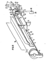
- the multilayer continuous paper is fed to the paper guide channel of the teleprinter via a tension compensation device 3 described later, which consists of a spring-mounted wire bracket with a paper guide saddle floating thereon.
- This paper guide channel contains a guide plate 5, which is tangentially aligned away from the motor-driven platen roller 4, with a paper transport shaft 7 mounted on one side below the writing point and provided with only one pressure roller, and one adjoining the paper transport shaft 7 the resilient paper pressure bar 8, which extends over the entire width of the paper roller.
- a writing head 9 with a drive device is moved line by line along the recording medium stretched over the writing roller 4.
- the paper transport described in more detail below is brought about by the motor-driven platen roller 4 in connection with the likewise motor-driven paper transport shaft by friction.
- the paper described is supported by a tray 6 in the lid of the housing 2.
- the core of the paper transport device consists of the paper transport shaft 7, which is motor-driven via a gear 11 with the platen roller 4 and is fixedly mounted on one side in the frame 2, and which is guided at its other end by a spring bracket 12 fixed to the frame becomes.
- a Paper feed shaft 7 there is a Jetan horrrolle 13 having a narrow relative to the width of the paper roll 32 has the cylindrical portion into contact with the - represents paper.
- the cylindrical region 32 tapers on both sides, and the conical side elements can also have a barrel shape.
- the angle ⁇ of the paper pressure bar 8 to the tangent to the platen roller 4 and the distance A between the paper pressure roller 13 and the paper pressure bar 8 on the circumference of the platen roller 4 are chosen so that the buckling resistance of light papers is sufficient to the pressure force F1 of the paper pressure bar 8 without jamming overcome.
- the diameter D of the paper pressure roller 13 is dimensioned correspondingly large.
- the paper pressure roller 13 itself is below that limited by the paper pressure roller 8
- the writing point of the printing device 90 is arranged so that the largest possible wrap angle ⁇ of the multilayer continuous paper 10 on the platen roller 4 results.
- the large wrap angle shown here of approximately 90 ° on the platen roller 4 permits a wide spread of the coefficient of friction of the platen roller covering.
- the central position of the barrel-shaped paper pressure roller 13 in a recess 15 of the paper guide plate 5 results in connection with a lateral paper guide 16 or with the guide of the tension compensation device 3.
- "Handlebar effect” which ensures the transport of the multi-layer continuous paper 10 without the layers being distorted.
- the speed ratio of platen roller 4 to paper pressure roller 13 is selected so that a small advance of 0.5% to 5% occurs on the pressure roller 13.
- This propulsion due to the different peripheral speeds of the platen roller 4 and the paper pressure roller 13, limits the formation of loops on the supply roller 1 and improves the wrap on the platen roller 4 in the case of multilayer paper.
- the size of the drive depends on the friction pairing of the pressure roller and paper and may also be greater than 5%.
- the pressure force F2 on the paper pressure roller 13 is generated by a frame-supported spring clip 12 made of wire via its torsion.
- the pressing force F2 can be very small since the rotary movement of the paper pressure roller 13 is generated by means of a gear stage of the platen roller 4 and is therefore independent of friction.
- the paper transport device consists of the platen roller 4, which is rotatably mounted in the frame 2 in a motor-driven manner.
- the paper transport shaft 7 connected to the platen roller 11 with the roller mounted thereon and with the paper transport shaft 7 firmly connected, barrel-shaped paper pressure roller 13.
- the paper transport shaft 7 with the paper pressure roller 13 is located at the end of the paper guide area 5 delimited by the paper guide plate and is rotatable on one side in the frame 2 and with its other end according to the direction of the arrow in an eyelet 17 of an arm of the rack-supported spring bracket 12 mounted.
- the paper pressure roller 13 can be pressed more or less strongly against the paper roller 4 or the paper 10 lying therebetween via the spring clip 12.
- a total swiveling of the paper pressure roller 13 is also possible for insertion and adjustment.
- For this purpose is fixed to the frame of the lead '18 mounted spring clip with its other arm is operatively connected to a pivot lever 19 which in turn is rotatably mounted about an axis 20th
- the swivel lever consists of a grip piece 21 with an attachment piece 22 arranged below the grip piece. In the illustrated pressed-on state of the paper pressure roller 13, one end of this spring piece rests against this attachment piece 22 under the torsional action of the spring clip 12. By pivoting the pivot lever 19 in accordance with the direction of the arrow shown, the paper roll of the platen roller 4 can be pivoted away.
- a scanning spring clip 23 is provided to detect the presence of paper in the paper guide.
- the scanning spring clip 23 engages with its loop-shaped bent scanning end 24 through an opening in the paper guide plate 5 and is supported on the platen roller 4.
- the scanning spring clip 23 is bent several times and with its outer end in a recess 25 of the Pa pier guide plates 5 stored stationary.
- the scanning spring clip 23 is guided by a guide piece 26 of the pivot lever 19 which is arranged eccentrically with respect to the axis of rotation of the part 20, the part of the scanning spring clip 23 lying opposite the scanning end having a U-shaped course and abutting an electrical scanning device 27 designed as a switch.
- the interaction of the scanning spring clip 23 with the electrical scanning device 27 and the spring clip 12 is as follows:
- the scanning end 24 and thus the scanning spring clip 23 are lifted off the platen roller 4.
- the swivel lever 19 is in the basic position shown with the paper pressure roller 13 pressed on. telsexual of the scanning bracket.
- the electrical scanning device is thus actuated and a switch contained in the electrical scanning device is thus opened.
- the opened switch interrupts a circuit consisting of a current source 29 and a warning lamp 30, so that the warning lamp 30 is extinguished.
- the electrical scanning device 27 can also be connected to a central microprocessor of the printing device which controls the operating states (on-off) as a function of the scanning device.
- the scanning spring clip rests on the platen roller S due to its spring behavior in accordance with the direction of the arrow shown.
- the button 28 is also moved in the direction of the arrow and the warning circuit is closed.
- the warning lamp 30 lights up.
- This warning lamp also lights up when the pivot lever 19 is moved in the direction of the arrow to pivot the paper transport shaft.
- the scanning spring clip 23 is pivoted through the angle 31 via the eccentric guide piece 2. 6, which in turn closes the warning circuit and thus lights up the warning lamp 30. It is thus possible to use the electrical scanning device 27 both for scanning the paper feed device on the paper end and for scanning the pivoted state of the paper pressure roller.
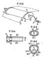
- the tension compensation device 3 (FIG. 3) provided for generating a pretension of the multi-layer continuous paper 10 between the supply roll 1 and the platen roller 4 consists of a spring clip 43 which is spring-mounted on an axis 41 by means of loops 42 and on which a paper guide clip 45 having lateral guide elements 44 is also included wider paper support surface 46 is floating, ie laterally displaceable, stored.
- the paper support surface 47 guides and centers the multilayer continuous paper 47.
- the lateral guides 44 are connected to the paper support surfaces 46/1 and 46/2 in an exchangeable manner via latching elements.
- the paper guide saddle is tubular in accordance with the sectional view of Figure 5 and has a plurality of paper support surfaces 46/1 and 46/2.
- the corresponding adjustment of the paper guide saddle provided with two paper support surfaces 46/1 and 46/2 to the corresponding width of the multi-layer continuous paper is carried out by simply pivoting the paper guide saddle 45 on the wire bracket 43.
- the wire bracket 43 slides in an elongated hole guide 49 and the axis length changes 4 from position 50 to the bottom sition 51 and vice versa. This means that the setting is made by simply swiveling the paper guide saddle 45 through 180 °.
- the paper 47 resting on the paper guide saddle 45 ensures, by its own weight or by the pressing force of the spring 42, that the paper guide saddle of the company cannot pivot.
- central guide 49 for the wire bracket 43 is designed in a star shape as shown in FIG. 6, then three paper support surfaces 46/3, 46/4 and 46/5 of different widths can be arranged on the circumference of the paper guide saddle 44.
- the wire bracket is moved to position 49/1 or 49/2 or 49/3.
- a particularly advantageous and simple embodiment of the paper feed device is obtained if, as shown in FIG. 7, the motor-driven paper pressure roller 13 is arranged above the writing point, ie behind the writing point in the feed direction. This results in a particularly simple wrapping with even contact of the paper 10 on the platen. Due to the large wrap, the pressure force of the pressure roller 13 can be reduced even further, so that even the thinnest papers with corresponding carbon intermediate layers can be transported through the paper transport device without any traces of pressure points.
- the tension compensation device 3 in connection with a funnel-shaped paper feed channel made from the lateral guide plate 5 with a counter plate 5/1, which can consist, for example, of a housing wall, leads to a particularly gentle treatment of the multi-layer paper.
- the curvature of the multi-layer recording medium pre-embossed by the paper roll 1 is passed through during the passage maintain the paper feed device and thus through the entire printing device.
- This uniform guidance of the multilayer continuous paper through the entire printing device results in a particularly good adjustment of the individual layers of the multilayer continuous paper to one another and thus a completely uniform line position.
- the entire printing device can be constructed in a particularly compact manner.
- a tear-off edge 32 can be arranged above the paper pressure roller 13, which, due to its proximity to the paper pressure roller 13, enables the printed continuous paper to be torn off particularly easily and precisely.
Landscapes
- Handling Of Continuous Sheets Of Paper (AREA)
- Registering, Tensioning, Guiding Webs, And Rollers Therefor (AREA)
Applications Claiming Priority (2)
| Application Number | Priority Date | Filing Date | Title |
|---|---|---|---|
| DE3240914 | 1982-11-05 | ||
| DE3240914 | 1982-11-05 |
Publications (3)
| Publication Number | Publication Date |
|---|---|
| EP0108388A2 true EP0108388A2 (fr) | 1984-05-16 |
| EP0108388A3 EP0108388A3 (en) | 1985-07-17 |
| EP0108388B1 EP0108388B1 (fr) | 1987-09-09 |
Family
ID=6177392
Family Applications (1)
| Application Number | Title | Priority Date | Filing Date |
|---|---|---|---|
| EP83110925A Expired EP0108388B1 (fr) | 1982-11-05 | 1983-11-02 | Dispositif de transport de papier pour installations d'impression avec papier continu ayant un seul rouleau presseur de papier |
Country Status (5)
| Country | Link |
|---|---|
| US (1) | US4561792A (fr) |
| EP (1) | EP0108388B1 (fr) |
| CA (1) | CA1225350A (fr) |
| DE (1) | DE3373440D1 (fr) |
| ZA (1) | ZA838230B (fr) |
Cited By (3)
| Publication number | Priority date | Publication date | Assignee | Title |
|---|---|---|---|---|
| DE3436684A1 (de) * | 1984-10-05 | 1986-04-10 | Siemens AG, 1000 Berlin und 8000 München | Papierfuehrungselement fuer druckeinrichtungen fuer endlospapier |
| US4592670A (en) * | 1984-06-29 | 1986-06-03 | International Business Machines Corporation | Angular motion paper feed release system |
| US4773782A (en) * | 1985-10-28 | 1988-09-27 | Canon Kabushiki Kaisha | Apparatus for transferring sheet material |
Families Citing this family (5)
| Publication number | Priority date | Publication date | Assignee | Title |
|---|---|---|---|---|
| JPS62208970A (ja) * | 1986-03-10 | 1987-09-14 | Minolta Camera Co Ltd | 印字装置 |
| IT1230273B (it) * | 1989-06-14 | 1991-10-18 | Bull Hn Information Syst | Azionatore automatico di dispositivo premicarta per stampante. |
| DE59300291D1 (de) | 1993-07-28 | 1995-07-27 | Siemens Nixdorf Inf Syst | Wärmefixiereinrichtung für ein- oder beidseitig bedruckte Aufzeichnungsträger eines Druck- oder Kopiergerätes. |
| SG87014A1 (en) * | 1998-12-28 | 2002-03-19 | Hewlett Packard Co | Apparatus for feeding media in a printer |
| US6364554B2 (en) * | 1999-12-29 | 2002-04-02 | Hewlett-Packard Company | Apparatus for feeding media in a printer |
Family Cites Families (24)
| Publication number | Priority date | Publication date | Assignee | Title |
|---|---|---|---|---|
| DE253360C (fr) * | ||||
| US991706A (en) * | 1909-12-08 | 1911-05-09 | Underwood Typewriter Co | Type-writing machine. |
| US1100442A (en) * | 1912-04-29 | 1914-06-16 | Remington Typewriter Co | Type-writing machine. |
| US1213189A (en) * | 1915-03-30 | 1917-01-23 | Underwood Computing Machine Co | Type-writing machine. |
| US1221236A (en) * | 1915-11-24 | 1917-04-03 | Remington Typewriter Co | Type-writing machine. |
| US1363294A (en) * | 1919-12-20 | 1920-12-28 | Underwood Typewriter Co | Typewriting-machine |
| US1539244A (en) * | 1923-03-03 | 1925-05-26 | Underwood Typewriter Co | Typewriting machine |
| US2142603A (en) * | 1938-01-31 | 1939-01-03 | Madge D Brown | Sheet signal for typewriters |
| DE851069C (de) * | 1938-11-19 | 1952-10-02 | Ncr Co | Belegfoerdervorrichtung fuer Schreib-, Rechen- oder Buchhaltungsmaschinen |
| US2353407A (en) * | 1941-06-26 | 1944-07-11 | Underwood Elliott Fisher Co | Typewriting machine |
| FR1407100A (fr) * | 1964-05-15 | 1965-07-30 | Bull Sa Machines | Perfectionnements à la mise en place et à l'avancement du papier dans des machines imprimantes |
| US3561660A (en) * | 1968-10-28 | 1971-02-09 | Burroughs Corp | Swiveling pressure roller assembly |
| US3586149A (en) * | 1969-02-07 | 1971-06-22 | Data Products Co | Web tensioning apparatus |
| US3572601A (en) * | 1969-04-14 | 1971-03-30 | Data Products Corp | Web feed system suitable for use in high-speed printers |
| US3519117A (en) * | 1969-05-23 | 1970-07-07 | Singer Co | Feed roller construction and drive |
| US3908810A (en) * | 1974-06-19 | 1975-09-30 | Teletype Corp | Printer paper roll holder with spring-controlled line feed tensioner |
| DE2503642C3 (de) * | 1975-01-29 | 1981-04-23 | Standard Elektrik Lorenz Ag, 7000 Stuttgart | Papierführung für automatisch betriebene Büromaschinen |
| US4114750A (en) * | 1975-08-06 | 1978-09-19 | Hydra Corporation | Printer system having local control for dynamically alterable printing |
| US4019619A (en) * | 1976-03-22 | 1977-04-26 | Printronix, Inc. | Paper feed sensing mechanism for printer |
| DE2713333C3 (de) * | 1977-03-25 | 1981-12-10 | Siemens AG, 1000 Berlin und 8000 München | Vorrichtung zur Führung des Papiers beim Papiertransport in Druckgeräten, insbesondere bei Fernschreibmaschinen |
| DE2847577A1 (de) * | 1978-11-02 | 1980-05-08 | Olympia Werke Ag | Tintenschreib-, druck-, kopierwerk mit andruckrollen auf drehbar gelagerter antriebswelle |
| DE2943241C2 (de) * | 1979-10-23 | 1982-05-13 | Mannesmann AG, 4000 Düsseldorf | Papierendeschaltvorrichtung für einen Drucker |
| US4341480A (en) * | 1979-12-26 | 1982-07-27 | General Electric Company | Feed mechanism for continuous and cut form paper |
| DE3014340C2 (de) * | 1980-04-15 | 1982-09-16 | Adlerwerke Vorm. Heinrich Kleyer Ag, 6000 Frankfurt | Einrichtung zum Andrücken und Abheben einer Papiertransportwelle von einer Schreibwalze einer Schreibmaschine, eines Druckers o.dgl. |
-
1983
- 1983-11-02 DE DE8383110925T patent/DE3373440D1/de not_active Expired
- 1983-11-02 EP EP83110925A patent/EP0108388B1/fr not_active Expired
- 1983-11-03 CA CA000440412A patent/CA1225350A/fr not_active Expired
- 1983-11-03 US US06/548,543 patent/US4561792A/en not_active Expired - Fee Related
- 1983-11-04 ZA ZA838230A patent/ZA838230B/xx unknown
Cited By (3)
| Publication number | Priority date | Publication date | Assignee | Title |
|---|---|---|---|---|
| US4592670A (en) * | 1984-06-29 | 1986-06-03 | International Business Machines Corporation | Angular motion paper feed release system |
| DE3436684A1 (de) * | 1984-10-05 | 1986-04-10 | Siemens AG, 1000 Berlin und 8000 München | Papierfuehrungselement fuer druckeinrichtungen fuer endlospapier |
| US4773782A (en) * | 1985-10-28 | 1988-09-27 | Canon Kabushiki Kaisha | Apparatus for transferring sheet material |
Also Published As
| Publication number | Publication date |
|---|---|
| EP0108388B1 (fr) | 1987-09-09 |
| US4561792A (en) | 1985-12-31 |
| CA1225350A (fr) | 1987-08-11 |
| ZA838230B (en) | 1984-06-27 |
| DE3373440D1 (en) | 1987-10-15 |
| EP0108388A3 (en) | 1985-07-17 |
Similar Documents
| Publication | Publication Date | Title |
|---|---|---|
| DE69702152T2 (de) | Papierendedetektionsgerät | |
| DE4335473C2 (de) | Wendeeinrichtung für einen bandförmigen Aufzeichnungsträger | |
| DE2655832C2 (de) | Trennvorrichtung zum Abtrennen von Papierbahnen in einem Drucker | |
| DE69314250T2 (de) | Papierschneidgerät mit beweglichem Rundmesser | |
| DE68928399T2 (de) | Apparat zum Ausgleichen der Wellungen | |
| EP0969969B1 (fr) | Imprimante servant a imprimer des feuilles individuelles et des bandes de papier sans fin | |
| DE69721525T2 (de) | Optisches Gerät zum Detektieren von Druckmedien in Druckern | |
| DE2618089A1 (de) | Vorrichtung zum einfuehren eines einzelnen blattfoermigen kopietraegers in die kopietraegertransportbahn eines kopiergeraetes | |
| DE2829827C2 (de) | Führungseinrichtung für Aufzeichnungsträger bei Druckwerken | |
| DE69108097T2 (de) | Selbstjustierender Wärmedruckkopf und Papierladevorrichtung. | |
| DE69623409T2 (de) | Schneidvorrichtung zum Schneiden von endlosen Materialbahnen | |
| EP0108388B1 (fr) | Dispositif de transport de papier pour installations d'impression avec papier continu ayant un seul rouleau presseur de papier | |
| DE2717315A1 (de) | Aufzeichnungstraegertransportvorrichtung fuer einen randgelochten aufzeichnungstraeger | |
| DE3139117C1 (de) | Variabler Falzapparat mit einem Schneidzylinderpaarund einem unterhalb diesem angeordneten Abreisswalzenpaar | |
| DE69801685T2 (de) | Drucker | |
| DE3214549C2 (de) | Transportvorrichtung für randgelochtes Faltpapier und für Rollenpapier | |
| DE3723391A1 (de) | Drucker | |
| EP0123310B1 (fr) | Alimentation en feuilles et en bandes pour imprimantes | |
| EP0111702B1 (fr) | Dispositifs d'introduction de papier avec un arbre de transport du papier basculant | |
| EP0127868B1 (fr) | Dispositif d'introduction de papier pour machines à écrire ou de bureau avec fente d'ajustement du papier située dans le canal de guidage du papier | |
| DE1262645B (de) | Rasterdrucker | |
| DE2212957B2 (de) | Einrichtung zur Bildung einer Kopiermaterialschleife innerhalb einer selbsttätigen Fördervorrichtung für Kopiermaterial in einer Kopiermaschine | |
| DE2503642C3 (de) | Papierführung für automatisch betriebene Büromaschinen | |
| EP0190629B1 (fr) | Dispositif de séparation pour bandes de formulaires ou feuilles séparées dans les machines de bureau, en particulier des imprimantes matricielles | |
| DE69609217T2 (de) | Medientransport bei einem Tintenstrahldrucker |
Legal Events
| Date | Code | Title | Description |
|---|---|---|---|
| PUAI | Public reference made under article 153(3) epc to a published international application that has entered the european phase |
Free format text: ORIGINAL CODE: 0009012 |
|
| AK | Designated contracting states |
Designated state(s): BE CH DE FR GB IT LI NL SE |
|
| 17P | Request for examination filed |
Effective date: 19841213 |
|
| PUAL | Search report despatched |
Free format text: ORIGINAL CODE: 0009013 |
|
| AK | Designated contracting states |
Designated state(s): BE CH DE FR GB IT LI NL SE |
|
| 17Q | First examination report despatched |
Effective date: 19861118 |
|
| GRAA | (expected) grant |
Free format text: ORIGINAL CODE: 0009210 |
|
| AK | Designated contracting states |
Kind code of ref document: B1 Designated state(s): BE CH DE FR GB IT LI NL SE |
|
| REF | Corresponds to: |
Ref document number: 3373440 Country of ref document: DE Date of ref document: 19871015 |
|
| ET | Fr: translation filed | ||
| ITF | It: translation for a ep patent filed | ||
| GBT | Gb: translation of ep patent filed (gb section 77(6)(a)/1977) | ||
| PLBE | No opposition filed within time limit |
Free format text: ORIGINAL CODE: 0009261 |
|
| STAA | Information on the status of an ep patent application or granted ep patent |
Free format text: STATUS: NO OPPOSITION FILED WITHIN TIME LIMIT |
|
| 26N | No opposition filed | ||
| PGFP | Annual fee paid to national office [announced via postgrant information from national office to epo] |
Ref country code: BE Payment date: 19891117 Year of fee payment: 7 |
|
| PGFP | Annual fee paid to national office [announced via postgrant information from national office to epo] |
Ref country code: NL Payment date: 19891130 Year of fee payment: 7 |
|
| PGFP | Annual fee paid to national office [announced via postgrant information from national office to epo] |
Ref country code: CH Payment date: 19900222 Year of fee payment: 7 |
|
| PGFP | Annual fee paid to national office [announced via postgrant information from national office to epo] |
Ref country code: GB Payment date: 19901018 Year of fee payment: 8 |
|
| PGFP | Annual fee paid to national office [announced via postgrant information from national office to epo] |
Ref country code: SE Payment date: 19901121 Year of fee payment: 8 |
|
| ITTA | It: last paid annual fee | ||
| PG25 | Lapsed in a contracting state [announced via postgrant information from national office to epo] |
Ref country code: LI Effective date: 19901130 Ref country code: CH Effective date: 19901130 Ref country code: BE Effective date: 19901130 |
|
| BERE | Be: lapsed |
Owner name: SIEMENS A.G. BERLIN UND MUNCHEN Effective date: 19901130 |
|
| PG25 | Lapsed in a contracting state [announced via postgrant information from national office to epo] |
Ref country code: NL Effective date: 19910601 |
|
| NLV4 | Nl: lapsed or anulled due to non-payment of the annual fee | ||
| REG | Reference to a national code |
Ref country code: CH Ref legal event code: PL |
|
| PG25 | Lapsed in a contracting state [announced via postgrant information from national office to epo] |
Ref country code: GB Effective date: 19911102 |
|
| PG25 | Lapsed in a contracting state [announced via postgrant information from national office to epo] |
Ref country code: SE Effective date: 19911103 |
|
| GBPC | Gb: european patent ceased through non-payment of renewal fee | ||
| PGFP | Annual fee paid to national office [announced via postgrant information from national office to epo] |
Ref country code: FR Payment date: 19921123 Year of fee payment: 10 |
|
| PGFP | Annual fee paid to national office [announced via postgrant information from national office to epo] |
Ref country code: DE Payment date: 19930122 Year of fee payment: 10 |
|
| PG25 | Lapsed in a contracting state [announced via postgrant information from national office to epo] |
Ref country code: FR Effective date: 19940729 |
|
| PG25 | Lapsed in a contracting state [announced via postgrant information from national office to epo] |
Ref country code: DE Effective date: 19940802 |
|
| REG | Reference to a national code |
Ref country code: FR Ref legal event code: ST |
|
| EUG | Se: european patent has lapsed |
Ref document number: 83110925.1 Effective date: 19920604 |