EP0108459B1 - Bodenbearbeitungsgerät - Google Patents
Bodenbearbeitungsgerät Download PDFInfo
- Publication number
- EP0108459B1 EP0108459B1 EP19830201577 EP83201577A EP0108459B1 EP 0108459 B1 EP0108459 B1 EP 0108459B1 EP 19830201577 EP19830201577 EP 19830201577 EP 83201577 A EP83201577 A EP 83201577A EP 0108459 B1 EP0108459 B1 EP 0108459B1
- Authority
- EP
- European Patent Office
- Prior art keywords
- hub
- tine
- cultivating
- holder
- members
- Prior art date
- Legal status (The legal status is an assumption and is not a legal conclusion. Google has not performed a legal analysis and makes no representation as to the accuracy of the status listed.)
- Expired
Links
- 239000002689 soil Substances 0.000 title claims description 8
- 230000005540 biological transmission Effects 0.000 description 1
- 238000010276 construction Methods 0.000 description 1
- 230000000694 effects Effects 0.000 description 1
- 230000002035 prolonged effect Effects 0.000 description 1
- 230000002787 reinforcement Effects 0.000 description 1
Images

Classifications
-
- A—HUMAN NECESSITIES
- A01—AGRICULTURE; FORESTRY; ANIMAL HUSBANDRY; HUNTING; TRAPPING; FISHING
- A01B—SOIL WORKING IN AGRICULTURE OR FORESTRY; PARTS, DETAILS, OR ACCESSORIES OF AGRICULTURAL MACHINES OR IMPLEMENTS, IN GENERAL
- A01B33/00—Tilling implements with rotary driven tools, e.g. in combination with fertiliser distributors or seeders, with grubbing chains, with sloping axles, with driven discs
- A01B33/06—Tilling implements with rotary driven tools, e.g. in combination with fertiliser distributors or seeders, with grubbing chains, with sloping axles, with driven discs with tools on vertical or steeply-inclined shaft
- A01B33/065—Tilling implements with rotary driven tools, e.g. in combination with fertiliser distributors or seeders, with grubbing chains, with sloping axles, with driven discs with tools on vertical or steeply-inclined shaft comprising a plurality of rotors carried by an elongate, substantially closed transmission casing, transversely connectable to a tractor
-
- A—HUMAN NECESSITIES
- A01—AGRICULTURE; FORESTRY; ANIMAL HUSBANDRY; HUNTING; TRAPPING; FISHING
- A01B—SOIL WORKING IN AGRICULTURE OR FORESTRY; PARTS, DETAILS, OR ACCESSORIES OF AGRICULTURAL MACHINES OR IMPLEMENTS, IN GENERAL
- A01B33/00—Tilling implements with rotary driven tools, e.g. in combination with fertiliser distributors or seeders, with grubbing chains, with sloping axles, with driven discs
- A01B33/08—Tools; Details, e.g. adaptations of transmissions or gearings
- A01B33/14—Attaching the tools to the rotating shaft, e.g. resiliently or flexibly-attached tools
- A01B33/146—Attaching the tools to the rotating shaft, e.g. resiliently or flexibly-attached tools the rotating shaft being oriented vertically or steeply inclined
Definitions
- the invention relates to a soil cultivating machine comprising a transverse frame part in which a plurality of. cultivating members are supported, the said members being power driven about vertical or substantially vertical shafts, that underneath the said frame part are provided with a time holder that extends horizontal or substantially horizontal and has two arms located diametrically opposite one another and adjoining a hub by means of which the said holder is secured for said shaft, strip-shaped tines being provided having a downwardly extending operative part and a horizontal or substantially horizontal fastening part that is bolted to the underside of said arm.
- the invention now has for its object to provide a tine fixation that is more reliable than the known one and thereby can easily be achieved in an inexpensive way.
- each tine has a rectangular fastening part having a flat end that engages a corresponding one of said contact surfaces of the hub.
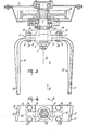
- the figures illustrate a device, more particularly a soil cultivating machine for preparing a seed bed comprising a hollow frame part 1 extending transversely of the direction of movement A.
- each of the cultivating members 3 comprises a tine carrier or holder 4 arranged on the end of the shaft 2 projecting from below the frame part 1.
- the carrier or holder 4 is provided near the middle with a hub 4A having an inner profile formed by key ways which are adapted to co-operate with corresponding key ways on the lower end of the shaft 2.
- Each shaft 2 has at its lower end a portion of smaller diameter which is provided with screwthread.
- each carrier or holder 4 has two diametrically opposite, flat arms 7 extending outwards away from the hub 4A and terminating at the top gradually in the hub 4A.
- the hub 4A On the underside the hub 4A has diametrically opposite contact surfaces 8, which extend tangentially to the rotary axis a of a cultivating member 3. Each contact surface 8 engages the flat end of a rectangular fastening part 9 of a strip-shaped tine 10.
- each tine 10 has a width corresponding at least substantially with the width of a contact surface 8 and an arm 7 and it extends at least substantially in a horizontal direction (Figs. 2 to 4).
- each arm 7 On the top side each arm 7 has a rim or rib 12 having its largest height on the side remote from the hub 4A and being at least substantially parallel to the longitudinal line of the arm.
- the top side of the rim or rib 12 goes through a bevelled part over in at least substantially straight, downwardly directed outer side (Fig. 3).
- the largest height of the rim 12 is about three times the thickness of an arm 7 of the holder4.
- each arm 7 has fastening points formed by holes through which a bolt 13 is passed onto which a nut 14 is screwed on the top side of each arm 7.
- a plane going through the longitudinal centre lines of the respective bores is at least substantially parallel to a contact surface 8.
- each tine 10 extends at least substantially parallel to the rotary axis a of a cultivating member 3 and is disposed so that the larger width extends at least substantially in a tangential direction.
- Said part is torsioned as a whole about its longitudinal axis in a manner such that a plane parallel to the broader side is at an angle of about 10° to the tangential plane and the front side of the operative part is further remote from the rotary axis a of the cultivating member 3 than the rear side.
- the rear side of the operative part extends perpendicularly downwards, whereas the front side is inclined to the rear along a straight line from top to bottom (Fig. 2) in a manner such that said side is at an angle of about 12° to a vertical plane going through the rotary axis of a cultivating member and the longitudinal centre line of the carrier or holder 4.
- each end the frame part 1 is provided with a plate 15 extending in upward direction in the direction of movement A.
- Each of the plates 15 is provided near the front side with a stub shaft 16, about which is pivotally arranged an arm 17 extending to the rear along a plate and being adjustable in a direction of height. Between the free ends of the arms 17 is arranged a freely rotatable roller 18.
- each of the shafts 2 is provided with a spur gear wheel 19 so that the gear wheels on neighbouring shafts 2 are drivably in mesh with one another.
- the shaft 2 of a cultivating member 3 is prolonged as far as into a gear box 20, in which said shaft is connected through a change-speed gear 21 with a shaft 22 extending in the direction of movement A and projecting from the front side of the gear box.
- the end of the shaft 22 protruding from the gear box can be coupled by means of an auxiliary shaft 23 with the power take-off shaft of a tractor.
- a trestle 24 is provided for attaching the machine to the three-point lifting device of a tractor.
- the machine coupled by means of the trestle 24 with the three-point lifting device of a tractor is propelled in the direction indicated by the arrow A and from the power take-off shaft through the auxiliary shaft 23 and the transmission described above the neighbouring cultivating members 3 are driven in the direction indicated by arrows in Fig. 1.
- the operative parts 11 of the strip-shaped tines 10 of neighbouring cultivating members work strips of soil at least adjoining one another.
- each strip-shaped tine 10 bears by a tangential end on the contact surface 8 on the underside of the hub 4A and the underside of an arm 7 and is fastened at two relatively spaced fastening points by means of the bolts 13, a very effective and reliable fixation of a strip-shaped tine 10 is obtained.
- the rim or rib 12 located between the bolts 13 on the top side of each of the arms 7 of a carrier or holder 4 provides not only a reinforcement of the arms but also a protection of the bolt fastening.
Landscapes
- Life Sciences & Earth Sciences (AREA)
- Engineering & Computer Science (AREA)
- Mechanical Engineering (AREA)
- Soil Sciences (AREA)
- Environmental Sciences (AREA)
- Soil Working Implements (AREA)
Claims (2)
1. Bodenbearbeitungsmaschine mit einem quer liegenden Rahmentteil (1), and dem mehrere Bearbeitungseinheiten abgestützt sind, die um vertikale oder annähernd vertikale Achsen (2) angetrieben sind, wobei jede Bearbeitungseinheit unterhalb des Rahmens (1) mit einem horizontal oder annähernd horizontal ausgerichteten Zinkenhalter (4) versehen ist, der zwei einander diametral gegenüberliegend angeordnete Arme (7) aufweist, die an eine Nabe (4A) angrenzen, mit der der Zinkenhalter an der Welle (2) befestigt ist, und bie der streifenförmige Zinken (10) vorgesehen sind, die einen nach unten gerichteten Arbeitsteil (11) und einen waagerechten oder annähernd waagerechten Befestigungsteil (9) aufweisen, der an der Unterseite des Armes (7) verschraubt ist, dadurch gekennzeichnet, daß an der Unterseite der Nabe (4A) vertikal ausgerichtete, einander diametral gegenüberliegende Anlageflächen (8) vorgesehen sind und jeder Zinken (10) ein rechteckiges Befestigungsteil (9) mit einem flachen Endstück aufweist, das an einer der entsprechenden Anlageflächen (9) der Nabel (4A) anliegt.
2. Bödenbearbeitungsmaschine nach Anspruch 1, bei der die Breite der Anlagefläche zumindest annähernd der Breite des flachen Endstückes des Befestigungsteiles entspricht.
Applications Claiming Priority (2)
| Application Number | Priority Date | Filing Date | Title |
|---|---|---|---|
| NL8204259 | 1982-11-03 | ||
| NL8204259A NL8204259A (nl) | 1982-11-03 | 1982-11-03 | Grondbewerkingsmachine. |
Publications (2)
| Publication Number | Publication Date |
|---|---|
| EP0108459A1 EP0108459A1 (de) | 1984-05-16 |
| EP0108459B1 true EP0108459B1 (de) | 1987-04-29 |
Family
ID=19840522
Family Applications (1)
| Application Number | Title | Priority Date | Filing Date |
|---|---|---|---|
| EP19830201577 Expired EP0108459B1 (de) | 1982-11-03 | 1983-11-02 | Bodenbearbeitungsgerät |
Country Status (5)
| Country | Link |
|---|---|
| EP (1) | EP0108459B1 (de) |
| DE (1) | DE3339330A1 (de) |
| FR (1) | FR2535148B1 (de) |
| GB (1) | GB2129263B (de) |
| NL (1) | NL8204259A (de) |
Families Citing this family (6)
| Publication number | Priority date | Publication date | Assignee | Title |
|---|---|---|---|---|
| NL8304356A (nl) * | 1983-12-20 | 1985-07-16 | Lely Nv C Van Der | Grondbewerkingsmachine. |
| GB8626626D0 (en) * | 1986-11-07 | 1986-12-10 | Dowdeswell Eng Co Ltd | Cultivator blade mounting |
| DE4106181A1 (de) * | 1991-02-27 | 1992-09-03 | Kverneland Klepp As | Bodenbearbeitungsgeraet |
| DE9201207U1 (de) * | 1992-02-01 | 1992-04-16 | Rabewerk GmbH + Co, 4515 Bad Essen | Wellen-Nabenverbindung mit einem Keilwellenprofil |
| GB2267808B (en) * | 1992-06-20 | 1995-08-16 | Nimrod Engineering Limited | Power harrow tines |
| FR2780236B1 (fr) | 1998-06-26 | 2000-09-08 | Tiverton Limited | Herse rotative et dents pour l'equipement d'une telle herse |
Family Cites Families (8)
| Publication number | Priority date | Publication date | Assignee | Title |
|---|---|---|---|---|
| DE7827326U1 (de) * | 1978-09-14 | 1979-01-04 | Rabewerk Heinrich Clausing, 4515 Bad Essen | Kreiselegge |
| US2088141A (en) * | 1935-07-05 | 1937-07-27 | Radial Tillers Ltd | Rotary cultivator |
| DE1195996B (de) * | 1964-10-10 | 1965-07-01 | Holder Ges Mit Beschraenkter H | Bodenfraese mit Messersternen |
| GB1320331A (en) * | 1969-08-07 | 1973-06-13 | Rotary Hoes Ltd | Rotary cultivator blade assembly |
| GB1575656A (en) * | 1976-06-10 | 1980-09-24 | Lely Nv C Van Der | Soil cultivating machines |
| NL7702876A (en) * | 1977-03-17 | 1978-09-19 | Lely Nv C Van Der | Rotating tool soil cultivation machine - has tools extending downwards and outwards from rotors with portions extending forwards |
| NL7711983A (nl) * | 1977-11-01 | 1979-05-03 | Patent Concern Nv | Grondbewerkingsmachine. |
| DE7736797U1 (de) * | 1977-12-02 | 1978-03-30 | Rabewerk Heinrich Clausing, 4515 Bad Essen | Kreiselegge |
-
1982
- 1982-11-03 NL NL8204259A patent/NL8204259A/nl active Search and Examination
-
1983
- 1983-10-27 FR FR8317155A patent/FR2535148B1/fr not_active Expired
- 1983-10-29 DE DE19833339330 patent/DE3339330A1/de not_active Ceased
- 1983-11-02 GB GB08329253A patent/GB2129263B/en not_active Expired
- 1983-11-02 EP EP19830201577 patent/EP0108459B1/de not_active Expired
Also Published As
| Publication number | Publication date |
|---|---|
| GB2129263B (en) | 1986-02-05 |
| GB2129263A (en) | 1984-05-16 |
| DE3339330A1 (de) | 1984-05-03 |
| EP0108459A1 (de) | 1984-05-16 |
| FR2535148B1 (fr) | 1986-01-31 |
| GB8329253D0 (en) | 1983-12-07 |
| NL8204259A (nl) | 1984-06-01 |
| FR2535148A1 (fr) | 1984-05-04 |
Similar Documents
| Publication | Publication Date | Title |
|---|---|---|
| US4151883A (en) | Soil cultivating machines | |
| EP0108459B1 (de) | Bodenbearbeitungsgerät | |
| GB1593837A (en) | Soil cultivating implements | |
| US4254834A (en) | Soil working machine | |
| US3949813A (en) | Soil cultivators | |
| US4114695A (en) | Rotary harrow with pivotable coupling assembly | |
| US4224997A (en) | Soil cultivating implements | |
| US4641713A (en) | Soil cultivating machines | |
| US4175623A (en) | Soil cultivating implements | |
| US4106567A (en) | Soil cultivating implements | |
| EP0309011B1 (de) | Bodenbearbeitungsmaschine | |
| US4178996A (en) | Soil cultivating machine | |
| EP0250055B1 (de) | Bodenbearbeitungsgeräte | |
| US4354557A (en) | Soil cultivating implement | |
| EP0242932B1 (de) | Bodenbearbeitungsgeräte | |
| CN221058756U (zh) | 一种平行滚筒装配用锁紧限定结构 | |
| US4423786A (en) | Soil cultivating machines | |
| US4245704A (en) | Soil cultivating machine | |
| EP0304120B1 (de) | Bodenbearbeitungsmaschine | |
| US4566258A (en) | Device for working crop lying on the ground | |
| EP0262734B1 (de) | Bodenbearbeitungsmaschine | |
| US4436161A (en) | Soil cultivating implements | |
| EP0583850B1 (de) | Bodenbearbeitungsmaschine | |
| EP0166493B1 (de) | Bodenbearbeitungsgeräte | |
| EP0237133B1 (de) | Bodenbearbeitungselement, insbesondere ein Zinken, für ein Bodenbearbeitungsgerät |
Legal Events
| Date | Code | Title | Description |
|---|---|---|---|
| PUAI | Public reference made under article 153(3) epc to a published international application that has entered the european phase |
Free format text: ORIGINAL CODE: 0009012 |
|
| AK | Designated contracting states |
Designated state(s): IT |
|
| 17P | Request for examination filed |
Effective date: 19841024 |
|
| GRAA | (expected) grant |
Free format text: ORIGINAL CODE: 0009210 |
|
| AK | Designated contracting states |
Kind code of ref document: B1 Designated state(s): IT |
|
| ITF | It: translation for a ep patent filed | ||
| PLBE | No opposition filed within time limit |
Free format text: ORIGINAL CODE: 0009261 |
|
| STAA | Information on the status of an ep patent application or granted ep patent |
Free format text: STATUS: NO OPPOSITION FILED WITHIN TIME LIMIT |
|
| 26N | No opposition filed | ||
| ITTA | It: last paid annual fee |