EP0108527A2 - Optische Einrichtung zur Fernüberwachung einer Atmosphäre und Verfahren zur Bestimmung eines Fremdstoffes in einer Flüssigkeit - Google Patents
Optische Einrichtung zur Fernüberwachung einer Atmosphäre und Verfahren zur Bestimmung eines Fremdstoffes in einer Flüssigkeit Download PDFInfo
- Publication number
- EP0108527A2 EP0108527A2 EP83306306A EP83306306A EP0108527A2 EP 0108527 A2 EP0108527 A2 EP 0108527A2 EP 83306306 A EP83306306 A EP 83306306A EP 83306306 A EP83306306 A EP 83306306A EP 0108527 A2 EP0108527 A2 EP 0108527A2
- Authority
- EP
- European Patent Office
- Prior art keywords
- cord
- light
- fluid
- substance
- extending
- Prior art date
- Legal status (The legal status is an assumption and is not a legal conclusion. Google has not performed a legal analysis and makes no representation as to the accuracy of the status listed.)
- Withdrawn
Links
- 239000000126 substance Substances 0.000 title claims abstract description 57
- 239000012530 fluid Substances 0.000 title claims abstract description 29
- 238000000034 method Methods 0.000 title claims abstract description 11
- 239000000835 fiber Substances 0.000 claims abstract description 36
- 239000012528 membrane Substances 0.000 claims abstract description 7
- 230000003287 optical effect Effects 0.000 claims description 11
- 238000012360 testing method Methods 0.000 claims description 10
- 238000005520 cutting process Methods 0.000 claims description 6
- 238000004804 winding Methods 0.000 claims description 5
- 230000008859 change Effects 0.000 claims description 3
- 238000001514 detection method Methods 0.000 claims description 3
- 239000000463 material Substances 0.000 claims description 3
- 230000009969 flowable effect Effects 0.000 claims description 2
- 238000004891 communication Methods 0.000 claims 1
- 239000007787 solid Substances 0.000 abstract description 7
- 150000001875 compounds Chemical class 0.000 description 9
- 239000011159 matrix material Substances 0.000 description 7
- 230000006870 function Effects 0.000 description 6
- 230000031700 light absorption Effects 0.000 description 6
- 239000007789 gas Substances 0.000 description 5
- 238000001228 spectrum Methods 0.000 description 5
- 238000010521 absorption reaction Methods 0.000 description 4
- 239000008280 blood Substances 0.000 description 4
- 210000004369 blood Anatomy 0.000 description 4
- 230000008878 coupling Effects 0.000 description 4
- 238000010168 coupling process Methods 0.000 description 4
- 238000005859 coupling reaction Methods 0.000 description 4
- 238000002329 infrared spectrum Methods 0.000 description 4
- 230000008569 process Effects 0.000 description 4
- 239000000853 adhesive Substances 0.000 description 3
- 230000001070 adhesive effect Effects 0.000 description 3
- 230000005670 electromagnetic radiation Effects 0.000 description 3
- 230000005855 radiation Effects 0.000 description 3
- ABJSOROVZZKJGI-OCYUSGCXSA-N (1r,2r,4r)-2-(4-bromophenyl)-n-[(4-chlorophenyl)-(2-fluoropyridin-4-yl)methyl]-4-morpholin-4-ylcyclohexane-1-carboxamide Chemical compound C1=NC(F)=CC(C(NC(=O)[C@H]2[C@@H](C[C@@H](CC2)N2CCOCC2)C=2C=CC(Br)=CC=2)C=2C=CC(Cl)=CC=2)=C1 ABJSOROVZZKJGI-OCYUSGCXSA-N 0.000 description 2
- LFQSCWFLJHTTHZ-UHFFFAOYSA-N Ethanol Chemical compound CCO LFQSCWFLJHTTHZ-UHFFFAOYSA-N 0.000 description 2
- 230000005574 cross-species transmission Effects 0.000 description 2
- 125000000524 functional group Chemical group 0.000 description 2
- 125000002496 methyl group Chemical group [H]C([H])([H])* 0.000 description 2
- 238000012986 modification Methods 0.000 description 2
- 230000004048 modification Effects 0.000 description 2
- 238000012544 monitoring process Methods 0.000 description 2
- 239000013307 optical fiber Substances 0.000 description 2
- 230000035945 sensitivity Effects 0.000 description 2
- 238000002211 ultraviolet spectrum Methods 0.000 description 2
- 238000001429 visible spectrum Methods 0.000 description 2
- XLYOFNOQVPJJNP-UHFFFAOYSA-N water Substances O XLYOFNOQVPJJNP-UHFFFAOYSA-N 0.000 description 2
- YZCKVEUIGOORGS-OUBTZVSYSA-N Deuterium Chemical compound [2H] YZCKVEUIGOORGS-OUBTZVSYSA-N 0.000 description 1
- 239000004593 Epoxy Substances 0.000 description 1
- 238000002835 absorbance Methods 0.000 description 1
- 239000000654 additive Substances 0.000 description 1
- 230000000996 additive effect Effects 0.000 description 1
- 150000001298 alcohols Chemical class 0.000 description 1
- 230000004075 alteration Effects 0.000 description 1
- 230000003466 anti-cipated effect Effects 0.000 description 1
- 238000013459 approach Methods 0.000 description 1
- 239000012736 aqueous medium Substances 0.000 description 1
- 230000008033 biological extinction Effects 0.000 description 1
- 230000005540 biological transmission Effects 0.000 description 1
- 230000015572 biosynthetic process Effects 0.000 description 1
- 210000004204 blood vessel Anatomy 0.000 description 1
- 229920002678 cellulose Polymers 0.000 description 1
- 239000001913 cellulose Substances 0.000 description 1
- 238000003486 chemical etching Methods 0.000 description 1
- 230000021615 conjugation Effects 0.000 description 1
- 239000000470 constituent Substances 0.000 description 1
- 238000013461 design Methods 0.000 description 1
- 229910052805 deuterium Inorganic materials 0.000 description 1
- 238000010586 diagram Methods 0.000 description 1
- 239000003814 drug Substances 0.000 description 1
- 230000000694 effects Effects 0.000 description 1
- 238000001914 filtration Methods 0.000 description 1
- 125000002887 hydroxy group Chemical group [H]O* 0.000 description 1
- 238000002347 injection Methods 0.000 description 1
- 239000007924 injection Substances 0.000 description 1
- 239000007788 liquid Substances 0.000 description 1
- 239000002609 medium Substances 0.000 description 1
- 230000000704 physical effect Effects 0.000 description 1
- 238000004382 potting Methods 0.000 description 1
- 238000002360 preparation method Methods 0.000 description 1
- 230000001737 promoting effect Effects 0.000 description 1
- 230000001902 propagating effect Effects 0.000 description 1
- 239000011347 resin Substances 0.000 description 1
- 229920005989 resin Polymers 0.000 description 1
- 230000000284 resting effect Effects 0.000 description 1
- 238000000926 separation method Methods 0.000 description 1
- 238000007711 solidification Methods 0.000 description 1
- 230000008023 solidification Effects 0.000 description 1
- 230000007704 transition Effects 0.000 description 1
- WFKWXMTUELFFGS-UHFFFAOYSA-N tungsten Chemical compound [W] WFKWXMTUELFFGS-UHFFFAOYSA-N 0.000 description 1
- 229910052721 tungsten Inorganic materials 0.000 description 1
- 239000010937 tungsten Substances 0.000 description 1
Images

Classifications
-
- G—PHYSICS
- G02—OPTICS
- G02B—OPTICAL ELEMENTS, SYSTEMS OR APPARATUS
- G02B6/00—Light guides; Structural details of arrangements comprising light guides and other optical elements, e.g. couplings
- G02B6/24—Coupling light guides
- G02B6/26—Optical coupling means
- G02B6/264—Optical coupling means with optical elements between opposed fibre ends which perform a function other than beam splitting
-
- A—HUMAN NECESSITIES
- A61—MEDICAL OR VETERINARY SCIENCE; HYGIENE
- A61B—DIAGNOSIS; SURGERY; IDENTIFICATION
- A61B5/00—Measuring for diagnostic purposes; Identification of persons
- A61B5/145—Measuring characteristics of blood in vivo, e.g. gas concentration or pH-value ; Measuring characteristics of body fluids or tissues, e.g. interstitial fluid or cerebral tissue
- A61B5/1455—Measuring characteristics of blood in vivo, e.g. gas concentration or pH-value ; Measuring characteristics of body fluids or tissues, e.g. interstitial fluid or cerebral tissue using optical sensors, e.g. spectral photometrical oximeters
- A61B5/1459—Measuring characteristics of blood in vivo, e.g. gas concentration or pH-value ; Measuring characteristics of body fluids or tissues, e.g. interstitial fluid or cerebral tissue using optical sensors, e.g. spectral photometrical oximeters invasive, e.g. introduced into the body by a catheter
-
- G—PHYSICS
- G01—MEASURING; TESTING
- G01N—INVESTIGATING OR ANALYSING MATERIALS BY DETERMINING THEIR CHEMICAL OR PHYSICAL PROPERTIES
- G01N21/00—Investigating or analysing materials by the use of optical means, i.e. using sub-millimetre waves, infrared, visible or ultraviolet light
- G01N21/84—Systems specially adapted for particular applications
- G01N21/85—Investigating moving fluids or granular solids
- G01N21/8507—Probe photometers, i.e. with optical measuring part dipped into fluid sample
-
- G—PHYSICS
- G01—MEASURING; TESTING
- G01N—INVESTIGATING OR ANALYSING MATERIALS BY DETERMINING THEIR CHEMICAL OR PHYSICAL PROPERTIES
- G01N2201/00—Features of devices classified in G01N21/00
- G01N2201/08—Optical fibres; light guides
Definitions
- the present invention relates to the sample chamber, cuvettes or sample cells used in most infrared, ultraviolet or visible wavelength spectrophotometer instruments designed to detect, measure or quantify specific chemical substances.
- Spectrophotometric instrumentation used for the qualitative and quantitative determination of chemical substances, plays a principle role in the disciplines of medicine, chemistry and physics, as well as in military and industrial applications and a variety of other uses. These instruments have a function based on a phenomenon of nature in which atoms and/or molecules either emit or absorb energy as they change from one energy state to another.
- the type of energy involved in this process is electromagnetic radiation, that is, light (visible, infrared, ultraviolet), X-rays, radio and radar waves. These are all simply different parts of a broad spectrum that stretches from gamma rays, whose wavelengths are measured in fractions of Angstrom units, to radio waves, whose wavelengths are measured in meters or even kilometers.
- the radiation When a beam of electromagnetic radiation is passed through a substance, the radiation (energy) can be either absorbed or transmitted, depending upon its frequency and the structure of the molecules it encounters.
- the energy gained by the molecule in this way may bring about increased vibration or rotation of the atoms, or may raise electrons to higher energy levels.
- the particular frequency of radiation that a given molecule can absorb depends upon the changes in vibrations or rotation or electron states that are permitted to a molecule of that structure.
- Each chemical compound therefore, has a spectrum that is a plot that shows how much electromagnetic radiation is absorbed or transmitted at each frequency. This spectrum is highly characteristic, like a finger print of the chemical compound's structure.
- Spectrophotometric instruments of the prior art generally use light as the energy medium for chemical detection. Light of wavelengths between about 4,000 Angstroms and 7,500 Angstroms is visible. Just beyond the red end of the visible spectrum (wavelengths greater than 7,500 Angstroms) lies the infrared region of light. Just beyond the violet end of the visible spectrum (wavelengths of less than 4,000 Angstroms) lies the ultraviolet region of light.
- Ultraviolet spectrophotometers commonly used measure the absorption of light in the visible and "near" ultraviolet region, that is, in the 2,000 to 7,500 Angstrom range. This light is of higher frequency and greater energy than infrared light and when it is absorbed by a molecule, the changes it produces are generally ones that require greater energy, such as changes in electron states.
- a molecule In a transition to a higher electron level, a molecule can go from any of a number of sub-levels, corresponding to various vibrational and rotational states, to any of a number of other sub-levels.
- ultraviolet light absorption bands are broad, and a typical ultraviolet spectrum shows only a few broad humps.
- Such a spectrum can conveniently be described in terms of the position of the top of the hump (wavelength maximum) and the intensity of that absorption (the extinction coefficient).
- the ultraviolet spectrum is used primarily to demonstrate relationships between functional groups (chiefly conjugation) rather than to show the presence of individual functional groups. This, however, provides adequate information for the qualitative and quantitative identification of chemical compounds.
- the infrared spectrum helps to reveal the structure of a compound by defining what constituent groups are present in, or absent from, the molecule.
- a particular group of atoms absorbs light of certain frequencies that are much the same from compound to compound, that is to say, they give rise to characteristic absorption bands.
- the hydroxyl group (-OH) of alcohols absorbs strongly at 28,000 to 33,000 Angstroms and the methyl group (-CH 3 ) absorbs strongly at 68,000 to 75,000 Angstroms. Therefore, two substances that have identical infrared spectra are, in effect, identical in thousands of different physical properties and must certainly be the same compound.
- Spectrophotometric instrumentation of the prior art is generally constructed such that light from a broad spectrum source (conventional incandescent bulb) is separated via prisms or a diffraction grating into discrete wavelengths.
- the monochromatic light can then be focused and collimated by lenses and mirrors so that the light is passed through some sort of sample chamber where high transparency sample holders (cuvettes or sample cells) containing the chemical substance being analyzed intercept the energy beam.
- sample holders cuvettes or sample cells
- the light passes through the chemical substance and continues on, via lenses and mirrors, to a detector apparatus, such as a photomultiplier tube.
- the signal generated by the detector apparatus is then amplified electronically and displayed or recorded.
- One embodiment of the present invention is a device for testing a substance in a fluid comprising a frame, fiber optic means to conduct light being mounted to the frame and extending through a path, the means including at least one opening extending therein allowing the substance to flow therein to receive said substance and change the light directed through the means.
- Another embodiment of the present invention is a device for checking a substance in a fluid comprising elongated fiber optic means including a plurality of openings extending therein changing the light directed through the means.
- a further embodiment of the present invention is an optical test cell to be used with a light measuring instrument comprising a fiber optic cord having a plurality of openings into which the substance to be tested may flow.
- Yet another embodiment of the present invention is a remote optical atmosphere monitor cell comprising a plate with upstanding posts, a fiber optic element wound around the posts and extending therebetween in multiple layers, and, a solidified mass enclosing the element and having a plurality of slots extending across and through the element into which the fluid to be monitored may flow.
- a further embodiment of the present invention is a method of detecting a foreign substance in a fluid comprising the steps of extending a fiber optic cord through a path, cutting openings in the cord at multiple locations between its opposite ends, directing the fluid into the opening, directing light through the cord; and comparing the light directed through the cord with the fluid in the openings to a standard.
- Yet a further object of the present invention is to provide a new and improved remote optical atmosphere monitor cell.
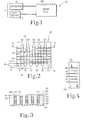
- the device includes a remote optical atmosphere monitor (ROAM) cell 10 operably connected to a spectrophotometer 11 including a light source 12 directing light into cell 10 and a detector or comparator 13 for the determination of the amount of light exiting cell 10.
- ROAM remote optical atmosphere monitor
- Cell 10 includes a mounting plate 14 (FIG. 2) upon which are fixed a plurality of winding posts 15 or similar structures in appropriate number and spacing to accommodate the anticipated length and size of a fiber optic light-wave guide 16.
- a mounting plate 14 FIG. 2
- six winding posts are cantileveredly mounted along one longitudinally extending edge portion of plate 14 with five additional mounting posts being cantileveredly mounted to the opposite edge portion of the plate and interspaced between the six posts.
- posts 17-22 are mounted to one side of plate 14 with posts 23-27 mounted to the opposite side.
- the winding posts are positioned such that the inside of post 17 aligns with the outside of opposite post 23 which in turn is aligned in similar fashion with post 18 and with the remaining posts aligned in similar fashion.
- Each mounting post is identical in configuration and has a series of circular grooves of specific size, number and spacing around its circumference such that the light guide fiber can fit in the groove to maintain alignment and separation.
- post 23 has a top circumferentially extending groove 28 for receiving light guide 16 with the next lower groove 29 being separated by a plate 30 integral with post 23.
- Light guide 16 is of conventional fiber optic design being cord configured and wound around each mounting post in sequential fashion. Light guide 16 is first wound around the lower groove of the first mounting post 17 and thus is spaced above plate 14. Guide 16 is bonded to post 17 with a permanent bonding epoxy or similar adhesive.
- guide 16 is passed, at the proper tension to maintain a straight axis, to the outside of post 23 and back and forth between each post in a parallel fashion, resting in the bottom groove until reaching the inside bottom of the last post 22.
- the light guide 16 is wound around and crosses in front of post 22 and is passed back to the second groove from the bottom of post 17 to repeat the process until all the grooves are filled.
- the winding of guide 16 on the mounting post can be set to whatever level is required for a specific monitoring function, and when the last level is achieved, the guide is bonded with the permanent bonding adhesive to the top of post 17 exiting the cell in the direction of arrow 34.
- a specified amount of light is directed into the cell in the direction of arrow 31 and passes from post 17 to post 23 in the direction of arrow 32, from post 23 to post 18 in the direction of arrow 33 and back and forth until finally exiting the cell in the direction of arrow 34.
- the guide and mounting posts are encased or encapsulated within an appropriate material such as a potting compound 35 (FIG. 3) including plastic, resin, etc.
- An open top embedding box may be used to form compound 35.
- Such a box is sized to receive plate 14 along with the mounting posts with two holes provided in the box of appropriate size to accommodate guide 16 entering and exiting the cell.
- the mounting plate 14 with the fiber wound mounting posts 15 are placed into the embedding box such that the entering and exiting wave guide 16 passes through the holes provided in the box.
- the embedding box is then filled with an appropriate material to embed the wave guide in a solid matrix 35 that is allowed to solidify completely in the configuration shown in FIG. 3.
- the solid matrix is initially in a flowable state and is poured into the box and subsequently allowed to solidify.
- slots 36 (FIG. 4) of varying number and dimensions are cut or holes 37 (FIG. 5) are drilled perpendicular to the direction and plane of light guide 16.
- These slots 36 or holes 37 transect light guide 16 that passes from post to post and creates a gap that separates, or a hole that penetrates, the core of the light guide.
- Slots 36 and 44-48 are perpendicular to cord 16 as the cord extends back and forth from mounting post to mounting post.
- the spacing between the slots 36 or holes 37 is selected with consideration being given to optical coupling and spillover, phenomena associated with fiber optic light transmission from fiber to fiber, both of which are functions of the diameter of the fiber core and the numerical aperture of the optical fiber.
- this spacing amounts to only a fraction of the core diameter.
- the solid matrix 35 is provided with a total of six slots all of which extend downwardly to slightly above plate 14 while cutting the light guide as it extends through a back and forth path between mounting posts.
- the light guide is wound around the posts to create six different horizontal layers which are cut by the six slots. That is, light guide 16 is arranged in six layers 38-43 (FIG. 3) with each layer being cut by the six slots 36 and 44-48 (FIG. 4).
- the cut surfaces of light guide 16 are shaped, polished or finished to the appropriate degree in order to obtain maximum optical signal.coupling.
- Commercially available devices, such as prisms, designed to gather or deliver light are fitted to the external ends of light guide 16 in turn attached to the light source 12 and detector apparatus 13.
- the ROAM Cell contains no moving parts. It functions, by passing a beam of frequency-modulated, optically-filtered and collimated light of suitable wavelength from sources, such as lasers, conventional lamps or light emitting diodes. These light sources, with the appropriate modulating, filtering and collimating systems, exist in instruments designed to quantify, measure or detect chemical substances via the process of light absorption at specific wavelengths by specific chemical molecular structure. Instruments of this type generally contain fixed cells, chambers or cuvettes that are filled with the chemical of interest, and through which the light energy is passed in order to interact the light with the chemical substance. The ROAM Cell will substitute for or replace these fixed cells or chambers and function at a site remote to the instrument.
- the fiber optic light-wave guide 16 carries the light source from the adapted commercial instrument to the cut surfaces of the slots or holes.
- a commercially available spectrophotometer which may be utilized with the ROAM Cell is Beckman Model 35, manufactured by Beckman Instrument, Inc., Irvine, California 92713.
- a spectrophotometer includes a light source of ultraviolet frequency from a Deuterium source such as Beckman Model No. 585699 or a visible light from a Tungsten source such as Beckman Model No. 56333.
- the optical &ignal propagating along the guide 16 will couple across the gap of the slot or hole and through the gap fluid media (gas or liquid) which contains the chemical substance to be quantified, measured or detected.
- the top surface 50 of the solid matrix is positioned to receive the incoming fluid with the foreign substance to be detected.
- surface 50 is placed in contact with the skin. Because the number of slots, or holes, the dimensions of the gaps, and the length and number of fiber layers are all variable, the path length of light through the slot or hole gap media can be any length practical. Therefore, light absorption in the gap by a specific chemical substance can provide a high degree of detection sensitivity, since this is a function of light path length.
- the light After coupling through the initial slot 48 gap media, the light is carried through the guide 16 to the next slots 47-44 and 36, then around post 23 to recross the slots again. This process can be repeated hundreds of times and since the light path is constructed in series, any light absorption at any single slot gap crossing is additive with any light absorption at any other crossing.
- the light After completing the slot crossings, the light returns via the exit fiber to the detector portion of the instrument being utilized and is appropriately quantified to determine the amount of light absorbed by the specific chemical substance.
- the amount of light absorbed by the specific chemical substance is directly related to the substance concentration and this concentration can easily be computed and displayed.
- the method of detecting a foreign substance in a fluid includes the step of extending the fiber optic cord through a path and then cutting openings in the cord at multiple locations between its opposite ends.
- the fluid to be tested is directed into the openings with light . passing through the cord, across the openings and through the fluid.
- the light directed through the cord, openings and fluid is then compared to a standard fluid without the foreign substance being present.
- certain foreign substances in fluids absorb specific wave-lengths of light energy.
- knowing the amount of electromagnetic energy at a specified wavelength directed initially into the ROAM Cell and by measuring the amount of light energy exiting the ROAM Cell at specific wavelengths it may be easily determined the type and amount of foreign substance within the fluid being measured.
- FIG. 5 shows another embodiment of the invention which may be utilized to quantify chemical substances in small spaces, such as blood vessels of the human body.
- the core of the optical fiber 60 (shown greatly enlarged at location 63) is pierced by laser drill or chemical etching, to produce a series of spaces or gaps 64 along its length, that are perpendicular to the axis of the fiber 60 core.
- the fiber 16 is then coated with a semi-permeable membrane 65 that allows the passage of water and water soluble chemicals into the gaps 64.
- a semi-permeable membrane is commercially available from Spectrum Medical Industries, Inc., 60916 Terminal Annex, Los Angeles, California 90054 and is a natural cellulose membrane tubing.
- Fiber 60 Specific light wavelengths from the instrumentation source 61 pass through the fiber 60, cross the gaps 64, and are absorbed by the chemical present in the aqueous media that infiltrates from the blood, through the membrane 65 and into the gaps 64.
- the absorption of the light is noted by the detector apparatus 62 and the concentration of the chemical substance computed and displayed.
- the fiber 60 is small enough to fit through a hypodermic needle device that allowing continuous monitoring of blood concentrations of chemicals. Fiber 60 is sized to be injected percutaneously into a-person with the outer end 66 being folded over as shown in the drawing and injected into the person with the opposite ends being attached to the light source and detector.
Landscapes
- Physics & Mathematics (AREA)
- Health & Medical Sciences (AREA)
- Life Sciences & Earth Sciences (AREA)
- General Health & Medical Sciences (AREA)
- General Physics & Mathematics (AREA)
- Optics & Photonics (AREA)
- Pathology (AREA)
- Biophysics (AREA)
- Medical Informatics (AREA)
- Immunology (AREA)
- Analytical Chemistry (AREA)
- Spectroscopy & Molecular Physics (AREA)
- Chemical & Material Sciences (AREA)
- Engineering & Computer Science (AREA)
- Biomedical Technology (AREA)
- Heart & Thoracic Surgery (AREA)
- Biochemistry (AREA)
- Molecular Biology (AREA)
- Surgery (AREA)
- Animal Behavior & Ethology (AREA)
- Public Health (AREA)
- Veterinary Medicine (AREA)
- Separation Using Semi-Permeable Membranes (AREA)
- Investigating Or Analysing Materials By Optical Means (AREA)
Applications Claiming Priority (2)
| Application Number | Priority Date | Filing Date | Title |
|---|---|---|---|
| US43864482A | 1982-11-03 | 1982-11-03 | |
| US438644 | 1995-05-10 |
Publications (2)
| Publication Number | Publication Date |
|---|---|
| EP0108527A2 true EP0108527A2 (de) | 1984-05-16 |
| EP0108527A3 EP0108527A3 (de) | 1984-12-27 |
Family
ID=23741440
Family Applications (1)
| Application Number | Title | Priority Date | Filing Date |
|---|---|---|---|
| EP83306306A Withdrawn EP0108527A3 (de) | 1982-11-03 | 1983-10-18 | Optische Einrichtung zur Fernüberwachung einer Atmosphäre und Verfahren zur Bestimmung eines Fremdstoffes in einer Flüssigkeit |
Country Status (1)
| Country | Link |
|---|---|
| EP (1) | EP0108527A3 (de) |
Cited By (5)
| Publication number | Priority date | Publication date | Assignee | Title |
|---|---|---|---|---|
| EP0198135A3 (de) * | 1985-04-17 | 1987-12-02 | Indiana University Foundation | Vorrichtung zur Fernüberwachung der Atmosphäre und Verfahren zum Nachweis eines Fremdstoffes in einer Flüssigkeit |
| WO1991018306A3 (en) * | 1990-05-22 | 1992-02-06 | Optex Biomedical Inc | Optical probe |
| US5173747A (en) * | 1990-09-20 | 1992-12-22 | Battelle Memorial Institute | Integrated optical directional-coupling refractometer apparatus |
| US5377008A (en) * | 1990-09-20 | 1994-12-27 | Battelle Memorial Institute | Integrated optical compensating refractometer apparatus |
| CN116762119A (zh) * | 2021-01-11 | 2023-09-15 | 昕诺飞控股有限公司 | 可伸缩的照明器材 |
Family Cites Families (1)
| Publication number | Priority date | Publication date | Assignee | Title |
|---|---|---|---|---|
| US4469398A (en) * | 1981-10-27 | 1984-09-04 | Oximetrix, Inc. | Optical connector for use during photometric analysis |
-
1983
- 1983-10-18 EP EP83306306A patent/EP0108527A3/de not_active Withdrawn
Cited By (5)
| Publication number | Priority date | Publication date | Assignee | Title |
|---|---|---|---|---|
| EP0198135A3 (de) * | 1985-04-17 | 1987-12-02 | Indiana University Foundation | Vorrichtung zur Fernüberwachung der Atmosphäre und Verfahren zum Nachweis eines Fremdstoffes in einer Flüssigkeit |
| WO1991018306A3 (en) * | 1990-05-22 | 1992-02-06 | Optex Biomedical Inc | Optical probe |
| US5173747A (en) * | 1990-09-20 | 1992-12-22 | Battelle Memorial Institute | Integrated optical directional-coupling refractometer apparatus |
| US5377008A (en) * | 1990-09-20 | 1994-12-27 | Battelle Memorial Institute | Integrated optical compensating refractometer apparatus |
| CN116762119A (zh) * | 2021-01-11 | 2023-09-15 | 昕诺飞控股有限公司 | 可伸缩的照明器材 |
Also Published As
| Publication number | Publication date |
|---|---|
| EP0108527A3 (de) | 1984-12-27 |
Similar Documents
| Publication | Publication Date | Title |
|---|---|---|
| US6694067B1 (en) | Cavity enhanced fiber optic and waveguide chemical sensor | |
| US8289511B2 (en) | Light-guiding flowcells with minimal stray light | |
| EP0461321B1 (de) | Verfahren und Vorrichtung zur Analyse von Formationsflüssigkeiten | |
| US6839140B1 (en) | Cavity-enhanced liquid absorption spectroscopy | |
| US6842548B2 (en) | Optical loop ring-down | |
| CA2768946C (en) | Multiple wavelength cavity ring-down spectroscopy | |
| US20180038798A1 (en) | Portable raman device | |
| US6912049B2 (en) | Electromagnetic radiation attenuating and scattering member with improved thermal stability | |
| EP2660584A2 (de) | Verfahren und Vorrichtung zur Quantifizierung von Lösungen aus mehreren Analyten | |
| DE3855043T2 (de) | Modularer chemischer sensor aus optischen fasern | |
| JPS61120947A (ja) | 光散乱測定用のサンプル・セル及び光散乱測定方法 | |
| RU2223479C2 (ru) | Способ и устройство для анализа изотопсодержащих молекул по спектру поглощения | |
| DE102017129454A1 (de) | Gasanalysemessgerät | |
| EP1797478A2 (de) | Multivariate optische berechnung thermaler selektivität | |
| JPH0363550A (ja) | 濃度測定装置および濃度測定方法 | |
| US6969857B2 (en) | Compensated infrared absorption sensor for carbon dioxide and other infrared absorbing gases | |
| US3433570A (en) | Multiple attenuated total reflection apparatus and method | |
| CN106198471B (zh) | 一种基于导光毛细管的生化荧光分析仪及其检测方法 | |
| CN101539017A (zh) | 利用太赫兹辐射的油-水-气分析设备和方法 | |
| US3814939A (en) | Chromato-fluorographic drug detector | |
| EP0108527A2 (de) | Optische Einrichtung zur Fernüberwachung einer Atmosphäre und Verfahren zur Bestimmung eines Fremdstoffes in einer Flüssigkeit | |
| EP0198135A2 (de) | Vorrichtung zur Fernüberwachung der Atmosphäre und Verfahren zum Nachweis eines Fremdstoffes in einer Flüssigkeit | |
| CA2746235C (en) | Optical fiber polarimetric chemical sensor with modulated injection of sample fluid | |
| CN105910994B (zh) | 一种基于光纤布拉格光栅的光声光谱气体检测装置及系统 | |
| Buerck et al. | Distributed measurement of chemicals using fiber optic evanescent wave sensing |
Legal Events
| Date | Code | Title | Description |
|---|---|---|---|
| PUAI | Public reference made under article 153(3) epc to a published international application that has entered the european phase |
Free format text: ORIGINAL CODE: 0009012 |
|
| AK | Designated contracting states |
Designated state(s): DE FR GB IT NL |
|
| PUAL | Search report despatched |
Free format text: ORIGINAL CODE: 0009013 |
|
| AK | Designated contracting states |
Designated state(s): DE FR GB IT NL |
|
| STAA | Information on the status of an ep patent application or granted ep patent |
Free format text: STATUS: THE APPLICATION IS DEEMED TO BE WITHDRAWN |
|
| 18D | Application deemed to be withdrawn |
Effective date: 19850828 |
|
| RIN1 | Information on inventor provided before grant (corrected) |
Inventor name: BROWN, DANIEL J. |