EP0108551A1 - Unité de propulsion pour véhicules - Google Patents
Unité de propulsion pour véhicules Download PDFInfo
- Publication number
- EP0108551A1 EP0108551A1 EP83306492A EP83306492A EP0108551A1 EP 0108551 A1 EP0108551 A1 EP 0108551A1 EP 83306492 A EP83306492 A EP 83306492A EP 83306492 A EP83306492 A EP 83306492A EP 0108551 A1 EP0108551 A1 EP 0108551A1
- Authority
- EP
- European Patent Office
- Prior art keywords
- speed
- change
- flywheel
- prime mover
- gearing
- Prior art date
- Legal status (The legal status is an assumption and is not a legal conclusion. Google has not performed a legal analysis and makes no representation as to the accuracy of the status listed.)
- Withdrawn
Links
- 238000009434 installation Methods 0.000 abstract description 2
- 238000006243 chemical reaction Methods 0.000 description 5
- 239000000314 lubricant Substances 0.000 description 4
- 238000005461 lubrication Methods 0.000 description 2
- 239000006096 absorbing agent Substances 0.000 description 1
- 230000015572 biosynthetic process Effects 0.000 description 1
- 238000002485 combustion reaction Methods 0.000 description 1
- 238000005755 formation reaction Methods 0.000 description 1
- 230000001050 lubricating effect Effects 0.000 description 1
- 238000007789 sealing Methods 0.000 description 1
- 230000035939 shock Effects 0.000 description 1
- 239000007858 starting material Substances 0.000 description 1
Images
Classifications
-
- B—PERFORMING OPERATIONS; TRANSPORTING
- B60—VEHICLES IN GENERAL
- B60K—ARRANGEMENT OR MOUNTING OF PROPULSION UNITS OR OF TRANSMISSIONS IN VEHICLES; ARRANGEMENT OR MOUNTING OF PLURAL DIVERSE PRIME-MOVERS IN VEHICLES; AUXILIARY DRIVES FOR VEHICLES; INSTRUMENTATION OR DASHBOARDS FOR VEHICLES; ARRANGEMENTS IN CONNECTION WITH COOLING, AIR INTAKE, GAS EXHAUST OR FUEL SUPPLY OF PROPULSION UNITS IN VEHICLES
- B60K17/00—Arrangement or mounting of transmissions in vehicles
- B60K17/02—Arrangement or mounting of transmissions in vehicles characterised by arrangement, location, or kind of clutch
Definitions
- This invention relates to power packs for motor vehicles. More particularly, the invention relates to a power pack including auxiliary change-speed gearing which may be overdrive gearing, suitable for use in a vehicle having a transversely mounted engine and front wheel drive.
- the conventional arrangement of power pack for a front engine, rear wheel drive vehicle with overdrive comprises a prime mover driving a change-speed gear box through a clutch, with an overdrive unit mounted at the output of the change-speed gear box and itself having an output connected to the vehicle propeller shaft.
- the total length of the prime mover, clutch, gear box and overdrive unit is considerable and usually greater than can be easily accommodated in a transverse engined vehicle. Nevertheless, it may be desired to provide an overdrive in such a vehicle, and it is an object of the present invention to provide for this.
- the invention provides a power pack for a motor vehicle, comprising a prime mover, a change-speed gear box, a clutch housing between and connected to the prime mover and change-speed bear box, and a clutch having an associated change-speed gearing arranged in series between the prime mover and gear box, characterised in that said associated change-speed gearing is disposed in the clutch housing with the clutch between said gearing and gear box.
- the change-speed gearing which may be an overdrive gearing
- the clutch housing With the clutch, relatively little space is occupied by the gearing in comparison with the conventional overdrive unit at the output of a gear box.
- the power pack can be suitable for transverse mounting in a vehicle.
- the change-speed gearing is incorporated in a flywheel assembly connected to the main output shaft (usually the crankshaft) of the prime mover, and provides for the flywheel to be driven at the same speed as said shaft or at a higher speed.
- Said change-speed gearing may comprise an epicyclic gear train, with control means operable selectively to connect and disconnect members of the train together and to prevent one member of the train from rotating.
- the change-speed gearing and control means therefore are disposed in an oil tight enclosure defined in part by said flywheel.
- the clutch may be a conventional type of dry clutch.
- the gearing may be arranged to be lubricated from the lubrication system of the prime mover.
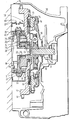
- the drawing shows a clutch housing 10, which when installed to form part of a power pack for a motor vehicle is connected to a prime mover at the left hand side of the drawing and a conventional change-speed gear box at the right hand side of the drawing.
- the housing contains a flywheel 11 provided with a conventional starter ring gear 12, and a conventional diaphragm spring clutch which provides for disconnection of drive between the flywheel 11 and an output shaft 13 which forms or is connected to the input shaft of the change-speed gear box.
- the clutch itself comprises a cover 14 bolted to the flywheel, a pressure plate 15, a diaphragm spring 16 having release fingers 17, and a driven plate 18 connected by a torsional shock absorber 19 to a hub 20 which is splined to the shaft 13.
- the driven plate 18 is clamped between the pressure plate 15 and flywheel 11, and the clutch is dis-engaged in known manner by a release mechanism, part of which is shown at 21, which presses on the innermost ends of release fingers 17.
- the flywheel In a conventional clutch installation, the flywheel would be connected directly to the output shaft of the prime mover, normally the crank shaft where the prime mover is an internal combustion piston engine.
- the invention provides, however, that the flywheel is connected to the output shaft of the prime mover through an epicyclic gear train which provides for the flywheel to be driven at the same speed as the output shaft or at a higher speed.
- the epicyclic gear train comprises a sun gear 22, planet gears 23 supported on pins 24 in a planet carrier 25, and an annulus gear 26 which is fixed to the rear face of the flywheel 11.
- a bearing 27 supports the flywheel relative to the planet carrier 25.
- the output shaft of the prime mover is indicated at 28, and has an end portion which is splined to the planet carrier 25 to drive same.
- the sun gear 22 is carried on shaft 28 by a bush 29, and is connected to a disc like element 30 terminating in a ring 31 which is rotationally fast with an annular sliding dog member 32.
- the member 32 has a groove 33 for receiving a selector fork, not shown, and is movable axially between a first position in which it connects the ring 31 to the annular gear 26 by way of dog formations 34, and a second position in which it connects the ring 31 to an annular reaction member 35 fixed to the prime mover by bolts 36.
- Lubrication of the epicyclic gear train is provided by oil contained within an annular casing 37 fixed to the prime mover.
- An oil seal, not shown, is provided at 38 where the casing 37 abuts the rotating flywheel 11.
- An operating member for moving the sliding dog member 32 enters casing 37 by way of a flexible sealing boot 39.
- Arrangement may be made for lubricant to enter casing 37 from the lubricating system of the prime mover, possibly by way of a weir arrangement to ensure that the required lubricant level within casing 37 is maintained. No lubricant, however, enters the main part of the clutch housing 10, and the clutch operates in a lubricant free environment.
- the clutch is of conventional design.
- the driven plate assembly 18, 19, 20 thereof is of conventional type, and there is no increase in the inertia of the output shaft 13 which forms or is connected to the input shaft of the change-speed gearbox of the power pack.
- the synchronising mechanism of the gearbox does not have to cope with additional inertia, as would be the case if the overdrive gearing were disposed between the clutch and gearbox.
- the mode of engagement between the sliding dog member 32 and the annulus gear 26 or reaction member 35 is of a synchromesh type.
Landscapes
- Engineering & Computer Science (AREA)
- Chemical & Material Sciences (AREA)
- Combustion & Propulsion (AREA)
- Transportation (AREA)
- Mechanical Engineering (AREA)
- Structure Of Transmissions (AREA)
Applications Claiming Priority (2)
| Application Number | Priority Date | Filing Date | Title |
|---|---|---|---|
| GB8231095 | 1982-10-30 | ||
| GB08231095A GB2132288B (en) | 1982-10-30 | 1982-10-30 | Auxiliary change-speed gear arrangement |
Publications (1)
| Publication Number | Publication Date |
|---|---|
| EP0108551A1 true EP0108551A1 (fr) | 1984-05-16 |
Family
ID=10533956
Family Applications (1)
| Application Number | Title | Priority Date | Filing Date |
|---|---|---|---|
| EP83306492A Withdrawn EP0108551A1 (fr) | 1982-10-30 | 1983-10-25 | Unité de propulsion pour véhicules |
Country Status (2)
| Country | Link |
|---|---|
| EP (1) | EP0108551A1 (fr) |
| GB (1) | GB2132288B (fr) |
Cited By (3)
| Publication number | Priority date | Publication date | Assignee | Title |
|---|---|---|---|---|
| DE19704456C1 (de) * | 1996-10-09 | 1998-05-20 | Nicolae Dr Ing Souca | Kupplungsanordnung |
| CN105526318A (zh) * | 2016-01-22 | 2016-04-27 | 吉林大学 | 一种基于两挡变速器的电驱动系统 |
| US10011282B2 (en) | 2013-12-20 | 2018-07-03 | Volvo Truck Corporation | Prime mover arrangement and method for controlling speed and torque output of a prime mover arrangement |
Citations (5)
| Publication number | Priority date | Publication date | Assignee | Title |
|---|---|---|---|---|
| FR1023588A (fr) * | 1950-08-18 | 1953-03-20 | Perfectionnements apportés aux systèmes de changements de vitesse | |
| FR1297985A (fr) * | 1961-06-29 | 1962-07-06 | Mécanisme de transmission de puissance à vitesse réglable | |
| FR1347067A (fr) * | 1962-10-22 | 1963-12-27 | Auto Transmissions Ltd | Perfectionnements aux dispositifs de transmission mécaniques |
| DE2461108A1 (de) * | 1973-12-22 | 1975-07-03 | Gkn Transmissions Ltd | Antriebsaggregat mit einem motor und einem planetengetriebe |
| DE2945357A1 (de) * | 1978-11-13 | 1980-05-14 | Yanmar Diesel Engine Co | Planetenradgetriebe fuer ein antriebssystem |
Family Cites Families (2)
| Publication number | Priority date | Publication date | Assignee | Title |
|---|---|---|---|---|
| GB908911A (en) * | 1960-07-01 | 1962-10-24 | Axel Charles Wickman | Variable speed power transmission mechanisms for vehicles |
| GB1061380A (en) * | 1964-09-11 | 1967-03-08 | Axel Wickerman Transmissions L | Motor vehicle transmission system |
-
1982
- 1982-10-30 GB GB08231095A patent/GB2132288B/en not_active Expired
-
1983
- 1983-10-25 EP EP83306492A patent/EP0108551A1/fr not_active Withdrawn
Patent Citations (5)
| Publication number | Priority date | Publication date | Assignee | Title |
|---|---|---|---|---|
| FR1023588A (fr) * | 1950-08-18 | 1953-03-20 | Perfectionnements apportés aux systèmes de changements de vitesse | |
| FR1297985A (fr) * | 1961-06-29 | 1962-07-06 | Mécanisme de transmission de puissance à vitesse réglable | |
| FR1347067A (fr) * | 1962-10-22 | 1963-12-27 | Auto Transmissions Ltd | Perfectionnements aux dispositifs de transmission mécaniques |
| DE2461108A1 (de) * | 1973-12-22 | 1975-07-03 | Gkn Transmissions Ltd | Antriebsaggregat mit einem motor und einem planetengetriebe |
| DE2945357A1 (de) * | 1978-11-13 | 1980-05-14 | Yanmar Diesel Engine Co | Planetenradgetriebe fuer ein antriebssystem |
Cited By (4)
| Publication number | Priority date | Publication date | Assignee | Title |
|---|---|---|---|---|
| DE19704456C1 (de) * | 1996-10-09 | 1998-05-20 | Nicolae Dr Ing Souca | Kupplungsanordnung |
| US10011282B2 (en) | 2013-12-20 | 2018-07-03 | Volvo Truck Corporation | Prime mover arrangement and method for controlling speed and torque output of a prime mover arrangement |
| CN105526318A (zh) * | 2016-01-22 | 2016-04-27 | 吉林大学 | 一种基于两挡变速器的电驱动系统 |
| CN105526318B (zh) * | 2016-01-22 | 2018-06-05 | 吉林大学 | 一种基于两挡变速器的电驱动系统 |
Also Published As
| Publication number | Publication date |
|---|---|
| GB2132288B (en) | 1986-03-19 |
| GB2132288A (en) | 1984-07-04 |
Similar Documents
| Publication | Publication Date | Title |
|---|---|---|
| US6401894B1 (en) | Multiple-clutch assembly | |
| US3614902A (en) | Planetary transmission | |
| US5846153A (en) | Clutch apparatus having planetary gear mechanism | |
| US7147095B2 (en) | Gearshift transmission for a motor vehicle with hydraulically actuated multiple clutch | |
| US6354974B1 (en) | Power train for use in motor vehicles and the like | |
| US5258651A (en) | Electrically biased starting reaction device for a power transmission | |
| JP3701911B2 (ja) | 油圧クラッチと遊星歯車装置とを備え、特に自動変速機のための、特定的には自動車用自動変速機のための組込みアッセンブリ、及び当該アッセンブリを使用する自動変速機 | |
| US7798027B2 (en) | Power takeoff and gearbox | |
| EP1455085A2 (fr) | Système de commande pour un moteur à combustion interne de véhicule automobile | |
| US4570503A (en) | Countershaft transmission | |
| US20200309232A1 (en) | Torque-Transmission Device | |
| JPS62215150A (ja) | 伝動装置 | |
| US2435930A (en) | Angle drive mechanism coupling power plant and vehicle axle | |
| US2687198A (en) | Clutch | |
| KR102557409B1 (ko) | 하이브리드 차량용 드라이브트레인 | |
| US5628703A (en) | Flywheel/clutch arrangement for manual-shift synchronized change-speed gearboxes | |
| US3600962A (en) | Multiple ratio, manually controlled power transmission mechanism with self energizing neutral clutch | |
| JP2003504575A (ja) | 自動変速機 | |
| KR20060048440A (ko) | 토크 전달 장치 시스템 | |
| CN114623208B (zh) | 混合动力变速箱总成和车辆 | |
| EP0660010B1 (fr) | Entraínement de véhicule | |
| US7325662B2 (en) | Dry friction launch clutch for an automatic transmission and method | |
| EP0293248B1 (fr) | Transmission de véhicule | |
| GB2132288A (en) | Auxiliary change-speed gear arrangement | |
| US3362259A (en) | Vehicle power plant |
Legal Events
| Date | Code | Title | Description |
|---|---|---|---|
| PUAI | Public reference made under article 153(3) epc to a published international application that has entered the european phase |
Free format text: ORIGINAL CODE: 0009012 |
|
| AK | Designated contracting states |
Designated state(s): DE FR GB IT NL SE |
|
| STAA | Information on the status of an ep patent application or granted ep patent |
Free format text: STATUS: THE APPLICATION IS DEEMED TO BE WITHDRAWN |
|
| 18D | Application deemed to be withdrawn |
Effective date: 19850117 |
|
| RIN1 | Information on inventor provided before grant (corrected) |
Inventor name: KETTELL, JOHN |