EP0108591A1 - Freins à disques pour véhicules - Google Patents
Freins à disques pour véhicules Download PDFInfo
- Publication number
- EP0108591A1 EP0108591A1 EP83306637A EP83306637A EP0108591A1 EP 0108591 A1 EP0108591 A1 EP 0108591A1 EP 83306637 A EP83306637 A EP 83306637A EP 83306637 A EP83306637 A EP 83306637A EP 0108591 A1 EP0108591 A1 EP 0108591A1
- Authority
- EP
- European Patent Office
- Prior art keywords
- lever
- brake
- pull
- rod
- piston
- Prior art date
- Legal status (The legal status is an assumption and is not a legal conclusion. Google has not performed a legal analysis and makes no representation as to the accuracy of the status listed.)
- Withdrawn
Links
- 230000033001 locomotion Effects 0.000 claims abstract description 20
- 230000008878 coupling Effects 0.000 claims abstract description 15
- 238000010168 coupling process Methods 0.000 claims abstract description 15
- 238000005859 coupling reaction Methods 0.000 claims abstract description 15
- 230000005540 biological transmission Effects 0.000 claims abstract description 11
- 238000006243 chemical reaction Methods 0.000 claims description 3
- 230000000295 complement effect Effects 0.000 claims description 3
- 239000002783 friction material Substances 0.000 claims description 3
- 230000007480 spreading Effects 0.000 abstract description 3
- 230000007246 mechanism Effects 0.000 description 8
- 210000001331 nose Anatomy 0.000 description 7
- 210000000887 face Anatomy 0.000 description 6
- 238000007789 sealing Methods 0.000 description 3
- 239000012530 fluid Substances 0.000 description 2
- 230000008901 benefit Effects 0.000 description 1
- 230000008933 bodily movement Effects 0.000 description 1
- 230000008859 change Effects 0.000 description 1
- 230000006835 compression Effects 0.000 description 1
- 238000007906 compression Methods 0.000 description 1
- 238000010276 construction Methods 0.000 description 1
- 238000006073 displacement reaction Methods 0.000 description 1
- 230000000694 effects Effects 0.000 description 1
- 238000005461 lubrication Methods 0.000 description 1
- 230000002093 peripheral effect Effects 0.000 description 1
- 230000000717 retained effect Effects 0.000 description 1
Images


Classifications
-
- F—MECHANICAL ENGINEERING; LIGHTING; HEATING; WEAPONS; BLASTING
- F16—ENGINEERING ELEMENTS AND UNITS; GENERAL MEASURES FOR PRODUCING AND MAINTAINING EFFECTIVE FUNCTIONING OF MACHINES OR INSTALLATIONS; THERMAL INSULATION IN GENERAL
- F16D—COUPLINGS FOR TRANSMITTING ROTATION; CLUTCHES; BRAKES
- F16D55/00—Brakes with substantially-radial braking surfaces pressed together in axial direction, e.g. disc brakes
- F16D55/02—Brakes with substantially-radial braking surfaces pressed together in axial direction, e.g. disc brakes with axially-movable discs or pads pressed against axially-located rotating members
- F16D55/04—Brakes with substantially-radial braking surfaces pressed together in axial direction, e.g. disc brakes with axially-movable discs or pads pressed against axially-located rotating members by moving discs or pads away from one another against radial walls of drums or cylinders
- F16D55/14—Brakes with substantially-radial braking surfaces pressed together in axial direction, e.g. disc brakes with axially-movable discs or pads pressed against axially-located rotating members by moving discs or pads away from one another against radial walls of drums or cylinders with self-tightening action, e.g. by means of coacting helical surfaces or balls and inclined surfaces
-
- F—MECHANICAL ENGINEERING; LIGHTING; HEATING; WEAPONS; BLASTING
- F16—ENGINEERING ELEMENTS AND UNITS; GENERAL MEASURES FOR PRODUCING AND MAINTAINING EFFECTIVE FUNCTIONING OF MACHINES OR INSTALLATIONS; THERMAL INSULATION IN GENERAL
- F16D—COUPLINGS FOR TRANSMITTING ROTATION; CLUTCHES; BRAKES
- F16D2125/00—Components of actuators
- F16D2125/18—Mechanical mechanisms
- F16D2125/20—Mechanical mechanisms converting rotation to linear movement or vice versa
- F16D2125/34—Mechanical mechanisms converting rotation to linear movement or vice versa acting in the direction of the axis of rotation
- F16D2125/36—Helical cams, Ball-rotating ramps
Definitions
- This invention relates to disc brakes for vehicles of the kind in which at least one friction disc rotatable within a stationary housing is adapted to be moved into engagement with a relatively stationary surface, and actuating means are provided for moving the disc into engagement with the said surface to apply the brake, the actuating means comprising at least one pressure plate which is located in the housing adjacent to the disc, and balls housed in recesses in the pressure plate and an adjacent face of a reaction member, actuating movement of the pressure place relative to the reacting member in the plane of the pressure plate being accompanied by axial movement of the pressure plate to urge the friction disc into engagement with the stationary surface.
- the actuating movement of the pressure plate can be effected hydraulically by an actuator comprising a cylinder and piston assembly of which the axis is substantially normal to that of the brake and of which one component is fixed relative to the housing and the other is movable and acts through a so-called rocking thrust coupling associated with a pull-rod passing through the actuator with a substantial clearance, and the pull-rod is adapted for connection to a manually-operable brake applying device, a hand lever for example.
- a brake of that kind is referred to below as "a brake of the kind set forth” and is particularly suitable for use in tractors and the like.
- a rocking thrust coupling is provided at an intermediate point in the length of a lever, a first pivotal connection is provided between the pull-rod and an intermediate point in the length of the lever, a second pivotal connection is provided between one end of the lever and the stationary housing, and a third pivotal connection is provided between the opposite end of the lever and a transmission member for connection to the manually-operable brake-applying device.
- the transmission member may comprise a flexible inextensible member,, for example a cable, rather than a rigid rod.
- the second and third pivotal connections may include lost-motion couplings so that movement of the lever when the brake is applied hydraulically is not transmitted to the manually-operable brake-applying device.
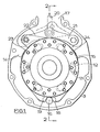
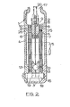
- the spreading disc brake illustrated in Figures 1 and 2 of the drawings comprises a stationary housing 1 mounted on a vehicle.
- the housing 1 comprises a casing 2 having a radial flange 3 at its peripheral edge, and a removable cover plate 4 abutting against the free end of the flange 3.
- a shaft 5 to be braked projects through the casing 2 into the housing.
- a pair of discs 6 are splined on the shaft 5 and each disc 6 is provided on opposite faces with lining rings 8 of friction material.
- an actuator assembly 9 for applying the brake is located in the housing 1.
- the actuator assembly 9 comprises a pair of pressure plates 10, 11, comprising annular rings, and balls 12 housed in pairs of complementary recesses 13 in adjacent faces of the two plates 10, 11.
- the plates 10, 11 are centered on three angularly spaced pilots 14, 15, 16 in the housing of which the pilots 14, 15 comprise lugs which extend radially from the flange 3 and are displaced angularly by equal distances from a radial opening 17 in the flange 3, and the pilot 16 comprises a torque or anchor pin which is received at opposite ends in end walls defined by the casing 3 and the cover plate 4, at a location immediately opposite the opening 17.
- Tension return springs 7 urge the pressure plates 10 and 11 towards each other.
- Each pressure plate 10, 11 is provided with a radial lug 18, 19 respectively, and each lug 18, 19 has a radial notch in it in which the pin 16 is received and which is of a circumferential length considerably greater than the diameter of the pin 16. Faces in the lugs 18, 19 at opposite ends of the notches act as torque transmitting faces for engagement with the pin 16 when the brake is applied, depending upon the direction of rotation of the shaft 5.
- the plates 10 and 11 are coupled to a actuating pull-rod 20 which is coupled to the inner ends of a pair of toggle links 21, 22 of which the inner ends are pivotally connected to lugs 23, 24 on respective pressure plates 10, 11.
- the pull-rod 20 is withdrawn relatively from the hpusing 1 with that movement transmitted to the plates 10, 11 through the toggle links 21 and 22 to cause relative rotation of the pressure plates 10, 11. Due to the presence of the balls 12, such angular movement is accompanied by separating movement of the pressure plates 10, 11 in a direction relatively away from each other, and against the force in the springs 7, by the camming tendency for the balls 12 to ride up ramps defined by end faces of the recesses 13, and the plates 10, 11 engage with the discs 6 to urge them into engagement with braking surfaces 25 and 26 comprising the inner faces of the casing 2 and the end plate 4.
- the plates 10, 11 are carried round with the discs 6 until movement of one of the plates is arrested by the engagement of its lug 18 or 19 with the pin 12.
- the other plate known as the energising or servo plate, continues to rotate with the discs, thereby increasing the camming effect of the balls 12 to enhance the friction grip of the brake.
- the pull-rod 20 is adapted to be withdrawn from the housing 1 by the mechanism illustrated in Figures 3 and 4 of the drawings in which the opening 17 is adapted in its periphery to provide a seating 30 for an hydraulic cylinder 31 which is secured to the housing 1 and is open at both ends.
- the axis of the cylinder 31 is substantially at right angles to that of the brake.
- the cylinder 31 has a stepped bore 3.2 in which works a hollow annular stepped piston 33 sealed by seals 34 and 35.
- the working space of the cylinder is the annular space 36 around the piston 33 at the step in diameter and a connection 37 is made to this space from a master cylinder 38 or other source of fluid under pressure.
- the outer end of the piston 33 is adapted to define a thrust transmitting portion 39 which acts through a force transmitting assembly 40 to transmit a brake-applying force from the piston 33 to the pull-rod 20 for moving the pressure plates 9 and 10 of the brake in a brake-applying direction.
- the force-transmitting assembly 40 comprises a lever assembly 41 in the form of two spaced parallel members 42 of substantial depth, each of which is formed on an edge adjacent to the brake with a radiused nose 43.
- the noses have rocking engagements with the thrust-transmitting portion 39 to define a part-circular rocking coupling.
- a trunnion mounted block 44 is pivotally connected between the members 42 at intermediate points in their lengths and in which the outer end of the pull-rod 20 is rigidly received.
- the members 42 are also interconnected at opposite ends by transverse pivot pins 45 and 46.
- the pivot pin 45 is received in slot 47 in a portion of the cylinder 31 which is straddled by the members and of which its open outer end faces outwardly away from that end of the housing 1, and the pivot pin 46 is received within an elongate slot 50 in a fitting 51 at the free end of a transmission member 52, suitably a flexible cable which leads to a hand brake-applying lever.
- the outer end of the cylinder 31 remote from the brake is closed by a flexible sealing boot 53.
- the hand-brake applying lever When the brake is to be applied mechanically or manually, for parking or in an emergency, the hand-brake applying lever is operated to apply a tension to the transmission member 52. This, in turn, applies an effort to one end of the lever assembly 41, which acts as a lever of the third order, and pivots about a fulcrum defined by the engagement of the pin 45 with the base of the slot 47, the rod 20 being relatively withdrawn from the housing 1 with the nose 31 moving away from the piston 33.
- the boot 53 is omitted and the members 42 comprising the lever assembly 41 are reduced in thickness to omit the noses 43.
- a thrust assembly 60 is interposed between the trunnion mounted block 44 and the piston 33.
- the thrust assembly 60 comprises a cylindrical member 61 through which the pull-rod 20 extends into the housing 1, and which co-operates at opposite ends between the block 44 and a collar 62, and the collar 62, in turn, acts on an annular thrust receiving face 63 at the adjacent end of the piston 33, through a thrust-transmitting washer 64 of low friction material.
- the washer 64 is received in a recess in the piston 33, in which it is retained against relative movement in the radial direction.
- the co-operating faces of the member 61 and the annular collar 62 are of part-spherical outline to define a part-spherical rocking thrust coupling, and a compression spring 65 acts between the block 44 and a shoulder on the member 61 to urge the member 61 relatively towards the brake in order normally to maintain interengaging faces in contact to avoid rattle and the relative displacement of the components in a radial direction in the inoperative position of brake, or when the brake is applied mechanically or manually.
- any circumferential movement of the block 44 when the brake is applied can be accommodated by the member 61 rocking with respect to the collar 62, and by the collar 62 sliding with respect to the washer 64 in a radial direction, with angular movement of the lever assembly 41 being accommodated by the trunnion 44 pivoting in the lever assembly 41.
- the hand-brake applying lever When the brake is to be applied mechanically or manually, the hand-brake applying lever is operated to apply a tension to the transmission member 52 which is coupled to the end of the lever assembly 41 remote from the pin 45. This, in turn, applies an effort to one end of the lever assembly 41, 'and pivots about a fulcrum defined by the pin 45.
- the trunnion block 44 separates from the member 61 due to the force in the spring 65, with the rod 20 sliding through the seal 66.
Landscapes
- Engineering & Computer Science (AREA)
- General Engineering & Computer Science (AREA)
- Mechanical Engineering (AREA)
- Braking Arrangements (AREA)
Applications Claiming Priority (2)
| Application Number | Priority Date | Filing Date | Title |
|---|---|---|---|
| GB8231769 | 1982-11-06 | ||
| GB8231769 | 1982-11-06 |
Related Child Applications (1)
| Application Number | Title | Priority Date | Filing Date |
|---|---|---|---|
| EP86106379.0 Division-Into | 1983-11-01 |
Publications (1)
| Publication Number | Publication Date |
|---|---|
| EP0108591A1 true EP0108591A1 (fr) | 1984-05-16 |
Family
ID=10534105
Family Applications (1)
| Application Number | Title | Priority Date | Filing Date |
|---|---|---|---|
| EP83306637A Withdrawn EP0108591A1 (fr) | 1982-11-06 | 1983-11-01 | Freins à disques pour véhicules |
Country Status (3)
| Country | Link |
|---|---|
| US (1) | US4549636A (fr) |
| EP (1) | EP0108591A1 (fr) |
| GB (1) | GB2129512B (fr) |
Cited By (2)
| Publication number | Priority date | Publication date | Assignee | Title |
|---|---|---|---|---|
| EP0195533A1 (fr) * | 1985-03-09 | 1986-09-24 | LUCAS INDUSTRIES public limited company | Freins à disque à auto-serrage |
| EP0197724A1 (fr) * | 1985-04-02 | 1986-10-15 | LUCAS INDUSTRIES public limited company | Freins à disque à autoserrage |
Families Citing this family (4)
| Publication number | Priority date | Publication date | Assignee | Title |
|---|---|---|---|---|
| GB8503142D0 (en) * | 1985-02-07 | 1985-03-13 | Lucas Ind Plc | Self-energising disc brakes |
| US4711327A (en) * | 1985-08-30 | 1987-12-08 | Lucas Industries | Self-energizing disc brakes |
| GB2182737B (en) * | 1985-11-06 | 1989-10-25 | Automotive Products Plc | Brake actuating mechanism |
| EP0263597A1 (fr) * | 1986-09-11 | 1988-04-13 | LUCAS INDUSTRIES public limited company | Freins à disque à auto-serrage |
Citations (6)
| Publication number | Priority date | Publication date | Assignee | Title |
|---|---|---|---|---|
| US3106268A (en) * | 1960-06-06 | 1963-10-08 | Gen Motors Corp | Brake |
| GB1166948A (en) * | 1966-05-24 | 1969-10-15 | Ford Motor Co | Motor Vehicle Brakes |
| GB1277345A (en) * | 1970-06-02 | 1972-06-14 | Girling Ltd | Improvements relating to disc brakes |
| US3779348A (en) * | 1970-09-03 | 1973-12-18 | Girling Ltd | Shoe-drum brakes |
| GB1363734A (en) * | 1970-10-21 | 1974-08-14 | Airheart Prod | Disc brakes |
| GB1547868A (en) * | 1975-05-08 | 1979-06-27 | Carr S | Disc brake actuator |
Family Cites Families (4)
| Publication number | Priority date | Publication date | Assignee | Title |
|---|---|---|---|---|
| GB1572602A (en) * | 1976-01-29 | 1980-07-30 | Girling Ltd | Disc brakes |
| US4235310A (en) * | 1979-03-07 | 1980-11-25 | Lambert Brake Corporation | Automatic adjuster for hydraulically actuated double disc brake |
| DE3066214D1 (en) * | 1980-01-04 | 1984-02-23 | Lucas Ind Plc | Improvements in disc brakes for vehicles |
| GB8310822D0 (en) * | 1982-04-30 | 1983-05-25 | Lucas Ind Plc | Disc brakes |
-
1983
- 1983-10-31 US US06/546,863 patent/US4549636A/en not_active Expired - Fee Related
- 1983-11-01 GB GB08329158A patent/GB2129512B/en not_active Expired
- 1983-11-01 EP EP83306637A patent/EP0108591A1/fr not_active Withdrawn
Patent Citations (6)
| Publication number | Priority date | Publication date | Assignee | Title |
|---|---|---|---|---|
| US3106268A (en) * | 1960-06-06 | 1963-10-08 | Gen Motors Corp | Brake |
| GB1166948A (en) * | 1966-05-24 | 1969-10-15 | Ford Motor Co | Motor Vehicle Brakes |
| GB1277345A (en) * | 1970-06-02 | 1972-06-14 | Girling Ltd | Improvements relating to disc brakes |
| US3779348A (en) * | 1970-09-03 | 1973-12-18 | Girling Ltd | Shoe-drum brakes |
| GB1363734A (en) * | 1970-10-21 | 1974-08-14 | Airheart Prod | Disc brakes |
| GB1547868A (en) * | 1975-05-08 | 1979-06-27 | Carr S | Disc brake actuator |
Cited By (2)
| Publication number | Priority date | Publication date | Assignee | Title |
|---|---|---|---|---|
| EP0195533A1 (fr) * | 1985-03-09 | 1986-09-24 | LUCAS INDUSTRIES public limited company | Freins à disque à auto-serrage |
| EP0197724A1 (fr) * | 1985-04-02 | 1986-10-15 | LUCAS INDUSTRIES public limited company | Freins à disque à autoserrage |
Also Published As
| Publication number | Publication date |
|---|---|
| GB2129512B (en) | 1985-12-11 |
| US4549636A (en) | 1985-10-29 |
| GB8329158D0 (en) | 1983-12-07 |
| GB2129512A (en) | 1984-05-16 |
Similar Documents
| Publication | Publication Date | Title |
|---|---|---|
| US3633715A (en) | Disc brake with spring brake and pressure-compensating self-adjuster | |
| US4383593A (en) | Hydraulically and mechanically operable disc brakes | |
| EP0110637B1 (fr) | Freins à disque pour véhicules | |
| US4611691A (en) | Hydraulic actuator assemblies for vehicle brakes | |
| US4121696A (en) | Disc brakes for vehicles | |
| US4549636A (en) | Disc brakes for vehicles | |
| US4795003A (en) | Self-energizing disc brakes | |
| US4685541A (en) | Self-energizing disc brakes | |
| US4067417A (en) | Self-energizing applied wedge actuator | |
| EP0190828A1 (fr) | Freins à disques à auto-serrage | |
| US4089392A (en) | Self-energizing disc brakes and actuator therefor | |
| EP0033032B1 (fr) | Perfectionnements aux freins à disque pour véhicules | |
| US4358002A (en) | Spreading disc brakes for vehicles | |
| US4508198A (en) | Spreading type disc brakes for vehicles | |
| GB2067692A (en) | Improvements in disc brakes for vehicles | |
| GB2075623A (en) | Disc brakes | |
| US4276963A (en) | Spreading disc brakes for vehicles | |
| GB2157377A (en) | Improvements in disc brakes for vehicles | |
| US3372778A (en) | Actuating means for spot-type disc brakes | |
| US4768625A (en) | Self-energizing disc brakes | |
| EP0316070A1 (fr) | Freins à disque renforçant automatiquement le freinage | |
| EP0067287B1 (fr) | Dispositif d'ajustement automatique pour freins | |
| EP0192395A1 (fr) | Freins à disque à auto-serrage | |
| EP0097447A1 (fr) | Freins à disque pour véhicules | |
| EP0224341A1 (fr) | Frein à disque à autoserrage |
Legal Events
| Date | Code | Title | Description |
|---|---|---|---|
| PUAI | Public reference made under article 153(3) epc to a published international application that has entered the european phase |
Free format text: ORIGINAL CODE: 0009012 |
|
| AK | Designated contracting states |
Designated state(s): DE FR IT |
|
| 17P | Request for examination filed |
Effective date: 19841006 |
|
| 17Q | First examination report despatched |
Effective date: 19860120 |
|
| STAA | Information on the status of an ep patent application or granted ep patent |
Free format text: STATUS: THE APPLICATION IS DEEMED TO BE WITHDRAWN |
|
| 18D | Application deemed to be withdrawn |
Effective date: 19870602 |
|
| RIN1 | Information on inventor provided before grant (corrected) |
Inventor name: EDWARDS, ROY ERNEST Inventor name: PRICE, ANTHONY GEORGE |