EP0108668A1 - System zum Betrieb und zur Überwachung von entlang einer Übertragungsstrecke verteilten Geräten - Google Patents
System zum Betrieb und zur Überwachung von entlang einer Übertragungsstrecke verteilten Geräten Download PDFInfo
- Publication number
- EP0108668A1 EP0108668A1 EP83401975A EP83401975A EP0108668A1 EP 0108668 A1 EP0108668 A1 EP 0108668A1 EP 83401975 A EP83401975 A EP 83401975A EP 83401975 A EP83401975 A EP 83401975A EP 0108668 A1 EP0108668 A1 EP 0108668A1
- Authority
- EP
- European Patent Office
- Prior art keywords
- digital
- link
- signal
- remote control
- channels
- Prior art date
- Legal status (The legal status is an assumption and is not a legal conclusion. Google has not performed a legal analysis and makes no representation as to the accuracy of the status listed.)
- Granted
Links
- 230000005540 biological transmission Effects 0.000 title claims abstract description 54
- 238000012423 maintenance Methods 0.000 title claims abstract description 18
- 238000012544 monitoring process Methods 0.000 claims abstract description 57
- 230000002457 bidirectional effect Effects 0.000 claims abstract description 5
- 230000033764 rhythmic process Effects 0.000 claims description 15
- 230000003287 optical effect Effects 0.000 claims description 13
- 239000013307 optical fiber Substances 0.000 claims description 8
- 230000001360 synchronised effect Effects 0.000 claims description 7
- 238000003780 insertion Methods 0.000 abstract description 19
- 230000037431 insertion Effects 0.000 abstract description 19
- 238000000605 extraction Methods 0.000 abstract description 16
- 230000001172 regenerating effect Effects 0.000 description 8
- 238000011084 recovery Methods 0.000 description 6
- 238000001514 detection method Methods 0.000 description 5
- 238000012545 processing Methods 0.000 description 5
- 238000001914 filtration Methods 0.000 description 4
- 238000005259 measurement Methods 0.000 description 4
- 239000000835 fiber Substances 0.000 description 3
- 230000008929 regeneration Effects 0.000 description 3
- 238000011069 regeneration method Methods 0.000 description 3
- RYGMFSIKBFXOCR-UHFFFAOYSA-N Copper Chemical compound [Cu] RYGMFSIKBFXOCR-UHFFFAOYSA-N 0.000 description 1
- 230000006978 adaptation Effects 0.000 description 1
- 230000032683 aging Effects 0.000 description 1
- 239000000969 carrier Substances 0.000 description 1
- 150000001768 cations Chemical class 0.000 description 1
- 229910052802 copper Inorganic materials 0.000 description 1
- 239000010949 copper Substances 0.000 description 1
- 239000000284 extract Substances 0.000 description 1
- 238000000034 method Methods 0.000 description 1
- 230000002250 progressing effect Effects 0.000 description 1
- 230000001105 regulatory effect Effects 0.000 description 1
- 230000011664 signaling Effects 0.000 description 1
- 238000001228 spectrum Methods 0.000 description 1
- 230000001960 triggered effect Effects 0.000 description 1
- 238000012800 visualization Methods 0.000 description 1
- 230000003313 weakening effect Effects 0.000 description 1
Images

Classifications
-
- H—ELECTRICITY
- H04—ELECTRIC COMMUNICATION TECHNIQUE
- H04B—TRANSMISSION
- H04B10/00—Transmission systems employing electromagnetic waves other than radio-waves, e.g. infrared, visible or ultraviolet light, or employing corpuscular radiation, e.g. quantum communication
- H04B10/07—Arrangements for monitoring or testing transmission systems; Arrangements for fault measurement of transmission systems
- H04B10/075—Arrangements for monitoring or testing transmission systems; Arrangements for fault measurement of transmission systems using an in-service signal
- H04B10/077—Arrangements for monitoring or testing transmission systems; Arrangements for fault measurement of transmission systems using an in-service signal using a supervisory or additional signal
- H04B10/0777—Monitoring line amplifier or line repeater equipment
-
- H—ELECTRICITY
- H04—ELECTRIC COMMUNICATION TECHNIQUE
- H04B—TRANSMISSION
- H04B2210/00—Indexing scheme relating to optical transmission systems
- H04B2210/07—Monitoring an optical transmission system using a supervisory signal
- H04B2210/074—Monitoring an optical transmission system using a supervisory signal using a superposed, over-modulated signal
Definitions
- the present invention is in the field of digital transmissions on cables.
- the routing of digital signals takes place, in general, on a bidirectional link established between two end stations and shared as soon as it exceeds a certain length, in sections delimited by intermediate stations.
- the maintenance and operation of such a link is carried out thanks to an intercommunication system between the stations and to a remote monitoring system for the equipment distributed along the link allowing the centralization of their operating information.
- the service channels for communicating between stations are generally routed by auxiliary pairs.
- these service channels are added to the digital traffic signal not by time division multiplexing but by superimposition on using auxiliary modulation. Indeed, it is desirable that these channels remain independent of the digital traffic signal processing circuits for reasons of reliability, consumption and operational flexibility.
- the online signal they are placed in a frequency band lower than that of digital traffic.
- the equipment of the link they are processed independently of the digital traffic signal. After receiving the online optical signal and converting it to an electrical signal, they are separated from the digital traffic signal by low-pass filtering, regenerated, decoded or reconfigured before being added again to the digital traffic signal by modulation. auxiliary to the optical transmitter.
- Each of the very low speed digital transmission and remote control channels is treated individually in each piece of equipment where it is separated from the traffic signal upon reception either by a routing filter or by a parity detector, regenerated, possibly reconfigured to add to it the operating information specific to the equipment considered and then recombined with the digital traffic signal just before the transmission of the online signal.
- remote monitoring systems can adapt, with their drawbacks, to a transmission link by optical fibers.
- they are difficult to reconcile with the presence of 64 kb / s service channels, which further increases the complexity of the filtering circuits used in each piece of equipment to separate the reception traffic signal, the digital intercommunication service channels, the very low speed digital channel of one remote monitoring system and possibly the remote control channel of the other remote monitoring system.
- the object of the present invention is to implement it easily using auxiliary circuits installed in each piece of equipment of the link that can be produced in integrated form.
- It relates to an operating and maintenance system for the equipment distributed along a digital cable link comprising a remote monitoring system with a very low speed digital transmission channel using the link in the company of a traffic signal. digital and a remote control channel transmitted via a low frequency jitter imposed at the rate of a digital signal carried by the link.
- the operating and maintenance system advantageously comprises an intercom system with digital low-speed service channels added to the digital traffic signal.
- the remote control channel of the remote monitoring system is transmitted by a very low frequency jitter imposed at the rate of the signal of the digital service channels.
- the operating and maintenance system may include an intercom system with a low speed digital signal of service channels obtained by redundant coding with prohibited configurations and added to the digital traffic signal.
- the remote control channel of the remote monitoring system is advantageously transmitted by a very low frequency jitter imposed at the rate of the digital signal of service channels while the digital very low speed channel of the remote monitoring system is transmitted by rapes of the law for coding the digital signal of service channels leading to prohibited configurations.
- the digital transmission link shown in FIG. 1 connects two end stations 10 and 30 in both directions. To do this, it uses an optical fiber 1, 2 per direction of transmission and intermediate regeneration stations of which only 50 is shown in Figure 1.
- the high-speed digital traffic signal 140 Mb / s or 560 Mb / s or more, is processed in the same way in both directions of transmission.
- the resulting optical signal conveyed by the optical fiber 1 or 2 arrives weakened at an intermediate regeneration station 50 where it is reconverted into an electrical signal, regenerated after recovery of its rhythm and delivered in optical form in a repeater circuit 51, 61.
- optical signal Progressing from one intermediate station to another the optical signal reaches the destination end station where it is converted into an electrical signal, regenerated after recovery of its rhythm, decoded and descrambled in a reception circuit 31 or 21 before d '' be issued on an exit 5 or 6.
- the digital transmission link is equipped with an operating and maintenance system including an intercom system. cation between stations with digital service channels at 64 kb / s routed by each direction of the link and a remote monitoring system, with local circuits 13, 53, 33, 43, 63, 23 for monitoring operation and electrical and mechanical environment of the circuits processing the digital traffic signal throughout the link, and with, on each direction of the link, a remote control channel and a digital transmission channel at very low speed allowing the synchronization of the local circuits of monitoring from any of the end stations and collecting, at any of the stations, information generated by these local monitoring circuits.
- the digital service channels at 64 kb / s as well as the remote control channel and the digital very low speed transmission channel using each direction of the link are, outside the stations, inserted in the optical signal carrying the digital traffic and are processed separately from the digital traffic signal at the stations by means of local insertion and / or extraction circuits 12, 52, 32, 42, 62, 22.
- the digital service channels at 64 kb / s of the intercom system may be ten in number per direction of the link, some used for voice, telephone or teleconferencing, and others for signaling and data transmission between stations. They are multiplexed in time for their routing on each direction of the link.
- a local circuit for operating service channels 20, 60, 40. provides each station with the demultiplexing of the incoming service channels and their possible local operation, the multiplexing of the outgoing service channels as well as the distribution between the incoming and outgoing service channels in transit.
- the local extraction and / or insertion circuits 12, 52, 32, 42, 62, 22 ensure the processing, at each station, of the multiplex signal of outgoing service channels generated by the local circuit for the exploitation of service with a view to its insertion into the optical signal transmitted in each direction of the link and the processing, at each station, of the multiplex signal of the incoming service channels extracted from the optical signal received from each direction of the link and intended for the local operating circuit of service channels.
- the multiplex signal of the service channels is coded in bipolar and used for an auxiliary modulation of the level of brightness of the electro-optical converters generating the signal. line.
- the local monitoring circuits 13, 53, 33, 43, 63, 23 are conventional circuits which monitor, for example, the error rates of the circuits regenerating the digital traffic signal, their supply voltage, the aging of the optical sources of the electro-optical converters as well as the state of the auxiliary equipment linked to its implementation: storage battery, sector, pressure sensor, etc.
- the very low speed remote control and digital transmission channels are routed on each direction, one by means of a very low frequency jitter imposed at the rate of the multiplex signal of service channels during its binary-bipolar coding and the other by violation of the bipolarity rule of the resulting signal.
- the service channels conveyed by certain fibers are unused, their signal being replaced by a digital signal allowing the violations of the law of bipolarity, for example a bipolar signal all one.
- the local extraction and insertion circuits 52, 62 of the intermediate stations 50 clock the multiplex signal of service channels transmitted on a direction of the link using the rhythm recovered from the multiplex signal of service channels received on the same sense of connection and are transparent to very low frequency jitter.
- the rhythm jitter is introduced at the start of the two directions of the connection by remote monitoring operating circuits 14 and 34 which are each placed in an end station 10, 30 and which each deliver to the local insertion circuit 12 , 42 a clock signal intended to clock the multiplex signal of outgoing service channels at a rate n. 64 kHz (n being the number of service channels per direction of the link) and periodically affected by bursts of jitter at very low frequency, for example 125 Hz constituting the remote control signals.
- the bursts of jitter once introduced on a direction of the connection propagate in an almost instantaneous way without weakening through.
- local extraction and / or insertion circuits 52, 62, 32 because the resulting frequency lines are, due to the very low frequency of the jitter, largely in the bandwidth of the filters ensuring the rhythm recoveries. They can also be easily detected at these filters.
- Each burst of jitter constitutes a remote control signal intended to synchronize the local surveillance circuits and to validate their information for their routing to the end stations by the two digital transmission channels at very low speed.
- the emissions of the bursts of jitter by the remote monitoring operating circuits 14 and 34 of the two end stations are synchronized with one another, a remote monitoring operating circuit 14, 34 detecting the jitter affecting the rhythm of the multiplexed signal of the incoming service channels received from the local extraction circuit 22, 32 and emitting a burst of jitter either after a delay of a few seconds or in response to the detection of a burst of jitter generated by the other circuit remote monitoring operation, which ensures the registration of puffs of jitter emitted on the two remote control channels.
- the end stations they are accompanied by a particular remote control order intended for the local monitoring circuits 13, 23, 43, 33 which is also generated by the remote monitoring operating circuit 14, 34.
- the bursts of jitter are detected separately for the two directions of the connection by a synchronization circuit 54 which generates a synchronization signal at the address of the local monitoring circuits 53, 63 from the bursts of jitter reaching it of one of the directions of the link, the direction chosen being the one in which the detection of bursts of jitter occurred first.
- the local insertion circuits 12, 42 of the end stations 10, 30 which process the multiplex signal of the outgoing service channels with a view to its insertion into the transmitted optical signal also generate, under the orders of the local monitoring circuits 13, 23, 33, 43, rapes of the law of bipolarity of the coding of multiplex signal from the outgoing service channels, rapes which allow the insertion of monitoring information of the operation of the end stations from the two very low speed digital transmission channels of the remote monitoring system.
- the local extraction and insertion circuits 52, 62 of the intermediate stations 50 relay these two very low speed transmission channels.
- the local extraction circuit 22, 32 of each end station detects the breaches of the bipolarity law of the coding of the multiplex signal of incoming service channels and delivers to the remote monitoring operating circuit 14, 34 the information conveyed by the two very low-speed digital transmission channels of the remote monitoring system.
- Information on the operation and the electrical and mechanical environment of the circuits processing the digital traffic signal throughout the link are all available in the remote monitoring operating circuit 14, 34 of each of the end stations where they are analyzed and operated independently. They are also fully accessible to intermediate stations by the local reception accesses of the two very low-speed digital transmission channels allowing the possible connection of a remote monitoring operating circuit 64 drawing part of the operating information from one of the digital transmission channels at very low speed and partly from each other.
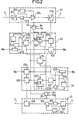
- FIG. 2 details an intermediate station 50.
- the main elements of the two unidirectional repeaters 51 and 61 are distinguished, one inserted in the optical fiber 1, the other in the optical fiber 2 with an opto-electric converter 511, 611 placed at the input and followed by a routing filter 513, 613, a regenerative circuit 514, 614 of the digital traffic signal clocked by a rhythm recovery circuit 512, 612 also connected to the output of the filter switch and an electro-optical converter 515, 615 placed at the output.
- the multiplexed service channel signal occupies a frequency band below the lower limit of that of the digital traffic signal. It is separated in the routing filter by low-pass filtering while that of the digital traffic signal is done by high-pass filtering. Its connection to the digital traffic signal is effected by an auxiliary modulation of the power or brightness level of the light state of the light source of the electro-optical converter 515, 615 which is moreover regulated in medium power and modulated in all or nothing by the digital traffic signal from the regenerative circuit 514, 614.
- the multiplexed signal of incoming service channels delivered by the routing filter 513, 613 is applied in the local extraction and insertion circuit 52, 62 to a regenerative circuit 528, 628 clocked by a clock circuit 522, 622 which recovers the coding rate of the multiplex signal of incoming service channels.
- the signal from the regenerative circuit 528, 628 arrives on the one hand at a rape detector 521, 621 which constitutes reception access to the very low digital transmission channel and on the other hand at a bipolar-binary decoding circuit 523, 623 controlled by the clock circuit 522, 622 and which delivers the multiplex signal of service channels in binary form. inbound Me to the possible destination of the local service channel operating circuit not shown in this figure 2.
- the multiplex signal of outgoing service channels Ms delivered by the local circuit for operating service channels is applied in the local extraction and insertion circuit 52, 62 to a binary-bipolar encoder 524, 624 clocked by the rhythm. of the multiplex signal of incoming channels received by the same direction of transmission, a rhythm which is recovered with its jitter at very low frequency by the clock circuit 522, 622, then applied to a generator of rapes of the bipolarity rule 525, 625 before being used for the auxiliary modulation of the electro-optical converter 515, 615.
- the clock circuits 522 and 622 of the extraction and insertion circuits 52 and 62 equipping the two directions of transmission of the station intermediate consist of tuned circuits.
- the synchronization circuit 54 receives from the two clock circuits 522 and 622 the rhythms recovered and extracts the respective jigs therefrom by means of phase-locked loops. It generates a synchronization signal at the address of the local monitoring circuits 53, 63 as soon as it recognizes a remote control signal in one of the jitter signals.
- the local monitoring circuits 53, 63 which receive operating information from the regenerative circuits 514, 614 but also information Pe and Pm on their electrical and mechanical environment freeze the results of their measurement, place them in a buffer register 526, 626 of each of the two local extraction and insertion circuits 52, 62 and then initialize a new measurement cycle.
- the outputs of the rape detectors 521, 621 from the local insertion and extraction circuits 52, 62 form reception accesses to the low-speed digital transmission channels of the remote monitoring system. They are connected via a multiplexer 527, 627 to the rape generator 525, 625.
- the multiplexer 527, 627 is also connected at the input to the buffer register 526, 626 and is controlled by the synchronization circuit 54. It realizes time multiplexing in the very low speed digital transmission channel, operating information in transit from other stations and operating information stored in the buffer register 526, 626. Its structure depends on the synchronous nature or asynchronous digital transmission path at very low speed.
- the channel is framed with a frame locking word generated at the end station at the origin of the channel considered and supplemented by the information relating to the operation of the stations as it passes through them, it can be formed by a frame lock word decoder circuit followed by an end of frame detection and complementation circuit according to a structure close to that described in French patent No. 2,276,744 filed by the applicant.
- the channel is synchronous, it can essentially consist of a shift register linked in chain with those of the other stations thanks to the modulation via the violations of the law of bipolarity of the multiplex signals. service channels using the same direction of the link and offset in synchronism with those of the other stations.
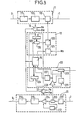
- FIG. 3 details an end station 10.
- the transmission circuit 11 essentially comprises a scrambler 111 giving pseudo-random properties to the digital traffic signal to be transmitted, an encoder 112 putting the traffic signal in a redundant binary form facilitating the detection of errors and an electro-optical converter 113 analogous to those 515, 615 of intermediate stations.
- the multiplex signal of the outgoing service channels Ms delivered by the local circuit for operating the service channels not shown in this figure is applied in the local insertion circuit 12 to a binary-bipolar encoder 121 and then to a rape generator of the bipolarity rule 122 before being extracted from the local insertion circuit 12 and used for the auxiliary modulation of the electro-optical converter 113.
- the rhythm of the binary-bipolar encoder 121 is generated in the local remote monitoring operating circuit 14 by a voltage controlled oscillator subjected at times to very low frequency phase modulation causing bursts of jitter. Simultaneously with each burst of jitter, the local remote monitoring operating circuit 14 generates an auxiliary synchronization signal at the address of the local monitoring circuits 13, 23.
- the monitoring circuits 13, 23 which receive operating information from the transmission circuit 11 and the reception circuit 12 as well as information Pm, Pe on the mechanical and electrical environment of the end station, stop the results of their measurement, the place in a buffer register 123 of the local insertion circuit 12 connected via an access circuit 124 to the rape generator 122 and begin a new measurement cycle.
- the structure of the access circuit 124 depends, like that of the multiplexers 527, 627 of the intermediate stations, on the nature of the very low-speed digital transmission channel of the remote monitoring system. .
- this access circuit consists of a frame lock word generator triggered by the local remote monitoring operating circuit. 14 simultaneously with the emission of a burst of jitter.
- a synchronous channel it can be a simple shift register put in chain with those constituting the multiplexers of the other stations thanks to the modulation via the rapes of bipolarity and shifted in synchronism with them.
- the reception circuit 21 begins with a unidirectional repeater with, as essential elements, an opto-electric converter 211 placed at the input and followed by a switching filter 213 and a regenerative circuit 214 clocked by a rhythm recovery circuit 212 also connected to the outlet of the switch filter. It continues with a decoder 215 and a descrambler 216 adapted to the encoder 112 and to the transmission scrambler 111.
- the multiplexed signal of the incoming service channels delivered by the routing filter 213 is applied in the local extraction circuit 22 to a regeneration circuit 228 clocked by a clock circuit 222 which recovers the coding rate of the multiplex signal of the incoming service channels.
- the signal from the regenerative circuit 228 is applied on the one hand to a rape detector 221 which constitutes the destination output of the very low speed digital transmission channel of the remote monitoring system, and on the other hand to a decoding circuit.
- bipolar-binary 223 controlled by the clock circuit 222 and which delivers in binary form the multiplexed signal of incoming service channels Me intended for the local circuit for operating service channels not represented in this FIG. 3.
- the clock circuit 222 delivers to the local circuit for operating the remote monitoring 14 the coding rhythm of the multiplex signal of incoming service channels affected by the jitter and allows the latter circuit a possible synchronization of the bursts of jitter which it generates. on those delivered by the local remote monitoring operating circuit of the other end station.
- the output signal from the rape detector 221 of the local extraction circuit 22 is applied to the local operating circuit of the remote monitoring 14 which receives through it the operating information generated by the local monitoring circuits of all the other stations of the link.
- a buffer register 224 also placed in the local extraction circuit 22 receives the operating information generated by the local monitoring circuits 13 and 23 from the end station itself and transfers them to the local operating circuit 14 on request. of the last.
- the operating and maintenance system for a digital link has the advantage of not specializing either the end stations or the intermediate stations, which gives it great ease of adaptation to the various configurations. possible: maintenance and operation of the entire link from an end station, an intermediate station or a center linked by teletransmission to an end or intermediate station, or maintenance and operation of the link by independent sections from intermediate stations or centers linked to them by teletransmission.
Landscapes
- Physics & Mathematics (AREA)
- Electromagnetism (AREA)
- Engineering & Computer Science (AREA)
- Computer Networks & Wireless Communication (AREA)
- Signal Processing (AREA)
- Time-Division Multiplex Systems (AREA)
Applications Claiming Priority (2)
| Application Number | Priority Date | Filing Date | Title |
|---|---|---|---|
| FR8217049A FR2534428A1 (fr) | 1982-10-12 | 1982-10-12 | Systeme d'exploitation et de maintenance d'equipements repartis le long d'une liaison de transmission numerique |
| FR8217049 | 1982-10-12 |
Publications (2)
| Publication Number | Publication Date |
|---|---|
| EP0108668A1 true EP0108668A1 (de) | 1984-05-16 |
| EP0108668B1 EP0108668B1 (de) | 1987-02-11 |
Family
ID=9278181
Family Applications (1)
| Application Number | Title | Priority Date | Filing Date |
|---|---|---|---|
| EP83401975A Expired EP0108668B1 (de) | 1982-10-12 | 1983-10-11 | System zum Betrieb und zur Überwachung von entlang einer Übertragungsstrecke verteilten Geräten |
Country Status (3)
| Country | Link |
|---|---|
| EP (1) | EP0108668B1 (de) |
| DE (1) | DE3369815D1 (de) |
| FR (1) | FR2534428A1 (de) |
Cited By (2)
| Publication number | Priority date | Publication date | Assignee | Title |
|---|---|---|---|---|
| EP0368549A3 (de) * | 1988-11-05 | 1991-07-17 | Stc Plc | Multiplexiertes Lichtwellenleitersystem mit Hilfskanal |
| WO1999010996A1 (de) * | 1997-08-22 | 1999-03-04 | Siemens Aktiengesellschaft | Verfahren und anordnung zum übertragen eines mit einem zusatzsignal modulierten optischen datensignals über nicht transparente funktionseinheiten |
Families Citing this family (1)
| Publication number | Priority date | Publication date | Assignee | Title |
|---|---|---|---|---|
| SE456190B (sv) * | 1983-10-14 | 1988-09-12 | Ericsson Telefon Ab L M | Forfarande att i ett fiberoptiskt transmissionssystem meta dispersionen hos den transmitterande optiska fibern |
Citations (4)
| Publication number | Priority date | Publication date | Assignee | Title |
|---|---|---|---|---|
| US3787613A (en) * | 1972-06-27 | 1974-01-22 | Bell Telephone Labor Inc | Pulse transmission system for conveying data and control words by means of alternating polarity pulses and violations thereof |
| EP0018295A2 (de) * | 1979-04-19 | 1980-10-29 | SAT (Société Anonyme de Télécommunications),Société Anonyme | Überwachungssystem für regenerative Verstärker enthaltende Fernmeldeverbindungen |
| EP0042229A1 (de) * | 1980-06-16 | 1981-12-23 | The Post Office | Digitale Übertragungssysteme |
| EP0059395A1 (de) * | 1981-02-20 | 1982-09-08 | Siemens Aktiengesellschaft | Verfahren zur Integration eines Dienstleitungsweges in Lichtleitübertragungsstrecken |
-
1982
- 1982-10-12 FR FR8217049A patent/FR2534428A1/fr active Granted
-
1983
- 1983-10-11 DE DE8383401975T patent/DE3369815D1/de not_active Expired
- 1983-10-11 EP EP83401975A patent/EP0108668B1/de not_active Expired
Patent Citations (4)
| Publication number | Priority date | Publication date | Assignee | Title |
|---|---|---|---|---|
| US3787613A (en) * | 1972-06-27 | 1974-01-22 | Bell Telephone Labor Inc | Pulse transmission system for conveying data and control words by means of alternating polarity pulses and violations thereof |
| EP0018295A2 (de) * | 1979-04-19 | 1980-10-29 | SAT (Société Anonyme de Télécommunications),Société Anonyme | Überwachungssystem für regenerative Verstärker enthaltende Fernmeldeverbindungen |
| EP0042229A1 (de) * | 1980-06-16 | 1981-12-23 | The Post Office | Digitale Übertragungssysteme |
| EP0059395A1 (de) * | 1981-02-20 | 1982-09-08 | Siemens Aktiengesellschaft | Verfahren zur Integration eines Dienstleitungsweges in Lichtleitübertragungsstrecken |
Non-Patent Citations (1)
| Title |
|---|
| NATIONAL TELECOMMUNICATIONS CONFERENCE, vol. 1, novembre 1981, New Orleans, IEEE, cat. no. 81CH1679-0, pages A1.4.1 - A1.4.5, New York, USA * |
Cited By (2)
| Publication number | Priority date | Publication date | Assignee | Title |
|---|---|---|---|---|
| EP0368549A3 (de) * | 1988-11-05 | 1991-07-17 | Stc Plc | Multiplexiertes Lichtwellenleitersystem mit Hilfskanal |
| WO1999010996A1 (de) * | 1997-08-22 | 1999-03-04 | Siemens Aktiengesellschaft | Verfahren und anordnung zum übertragen eines mit einem zusatzsignal modulierten optischen datensignals über nicht transparente funktionseinheiten |
Also Published As
| Publication number | Publication date |
|---|---|
| FR2534428A1 (fr) | 1984-04-13 |
| EP0108668B1 (de) | 1987-02-11 |
| FR2534428B1 (de) | 1984-11-30 |
| DE3369815D1 (en) | 1987-03-19 |
Similar Documents
| Publication | Publication Date | Title |
|---|---|---|
| FR2600473A1 (fr) | Dispositif de multiplexage pour un systeme de transmission numerique | |
| EP0792038B1 (de) | Überwachungssystem eines Multiwellenlängen-Ringnetzes | |
| EP0032328B1 (de) | Verfahren und Anlage zur Einleitung der Sicherung einer Leitung eines digitalen Übertragungskabels | |
| FR2486335A1 (fr) | Installation de telelocalisation pas-a-pas de circuits d'amplification intermediaires d'une liaison mic | |
| FR2533094A1 (fr) | Methode de controle d'un systeme de transmission numerique, systeme et repeteurs appliquant cette methode | |
| FR2544154A1 (fr) | Systeme de transmission des donnees pour des flutes sismiques | |
| EP2171862B1 (de) | System und verfahren zur unterdrückung der überlagerungsgeräusche in einem leitungsüberwachungsgerät | |
| CN112636867B (zh) | 一种频分复用的波长标签实现方法及系统 | |
| FR2693612A1 (fr) | Dispositif de raccordement d'une station à un réseau local comportant au moins un anneau. | |
| SK41096A3 (en) | Optical telecommunication method providing a transmitting and receiving service channel | |
| EP0053958A1 (de) | Verfahren zur Parallel-Serien-Umsetzung einer digitalen, parallelen Folge | |
| EP0108668B1 (de) | System zum Betrieb und zur Überwachung von entlang einer Übertragungsstrecke verteilten Geräten | |
| FR2494528A1 (fr) | Systeme de transmission a securite de service | |
| US20170244509A1 (en) | Wavelength conflict detection using coded pilot tone | |
| JP2003060623A (ja) | 差分波長分割多重/分離化方法とその装置 | |
| EP0097753A1 (de) | Tonempfänger für digitales Datenübertragungssystem | |
| FR2838901A1 (fr) | Procede et systeme de controle de la transmission de signaux optiques | |
| FR2829327A1 (fr) | Reseau en anneau realise a partir d'un bus optique double | |
| US7389044B2 (en) | Method and system for providing a signature signal in an optical network in the event of loss of a client | |
| EP1592159B1 (de) | Optisches Übertragungsnetz mit Baumstruktur | |
| FR2472898A1 (fr) | Reseau de transmission en boucle double | |
| KR20010014403A (ko) | 광섬유를 통한 정보 전송을 위한 파장 분할 멀티플렉스네트워크에서의 오버헤드 정보 전송 프로세스 | |
| EP1168695A1 (de) | Lichtwellenleiter-Unterwasserübertragung Netzwerk | |
| EP4192719B1 (de) | System und verfahren zur automatischen meldung des durchgangs eines schienenfahrzeugs auf einer fahrbahn | |
| JPS6352826B2 (de) |
Legal Events
| Date | Code | Title | Description |
|---|---|---|---|
| PUAI | Public reference made under article 153(3) epc to a published international application that has entered the european phase |
Free format text: ORIGINAL CODE: 0009012 |
|
| AK | Designated contracting states |
Designated state(s): BE DE FR GB NL SE |
|
| 17P | Request for examination filed |
Effective date: 19841109 |
|
| RAP1 | Party data changed (applicant data changed or rights of an application transferred) |
Owner name: ALCATEL |
|
| GRAA | (expected) grant |
Free format text: ORIGINAL CODE: 0009210 |
|
| AK | Designated contracting states |
Kind code of ref document: B1 Designated state(s): BE DE FR GB NL SE |
|
| REF | Corresponds to: |
Ref document number: 3369815 Country of ref document: DE Date of ref document: 19870319 |
|
| PLBE | No opposition filed within time limit |
Free format text: ORIGINAL CODE: 0009261 |
|
| STAA | Information on the status of an ep patent application or granted ep patent |
Free format text: STATUS: NO OPPOSITION FILED WITHIN TIME LIMIT |
|
| 26N | No opposition filed | ||
| PGFP | Annual fee paid to national office [announced via postgrant information from national office to epo] |
Ref country code: GB Payment date: 19940823 Year of fee payment: 12 |
|
| PGFP | Annual fee paid to national office [announced via postgrant information from national office to epo] |
Ref country code: SE Payment date: 19940922 Year of fee payment: 12 |
|
| PGFP | Annual fee paid to national office [announced via postgrant information from national office to epo] |
Ref country code: FR Payment date: 19940929 Year of fee payment: 12 Ref country code: BE Payment date: 19940929 Year of fee payment: 12 |
|
| PGFP | Annual fee paid to national office [announced via postgrant information from national office to epo] |
Ref country code: DE Payment date: 19940930 Year of fee payment: 12 |
|
| PGFP | Annual fee paid to national office [announced via postgrant information from national office to epo] |
Ref country code: NL Payment date: 19941031 Year of fee payment: 12 |
|
| EAL | Se: european patent in force in sweden |
Ref document number: 83401975.4 |
|
| PG25 | Lapsed in a contracting state [announced via postgrant information from national office to epo] |
Ref country code: GB Effective date: 19951011 |
|
| PG25 | Lapsed in a contracting state [announced via postgrant information from national office to epo] |
Ref country code: SE Effective date: 19951012 |
|
| PG25 | Lapsed in a contracting state [announced via postgrant information from national office to epo] |
Ref country code: BE Effective date: 19951031 |
|
| BERE | Be: lapsed |
Owner name: ALCATEL Effective date: 19951031 |
|
| PG25 | Lapsed in a contracting state [announced via postgrant information from national office to epo] |
Ref country code: NL Effective date: 19960501 |
|
| GBPC | Gb: european patent ceased through non-payment of renewal fee |
Effective date: 19951011 |
|
| PG25 | Lapsed in a contracting state [announced via postgrant information from national office to epo] |
Ref country code: FR Effective date: 19960628 |
|
| EUG | Se: european patent has lapsed |
Ref document number: 83401975.4 |
|
| PG25 | Lapsed in a contracting state [announced via postgrant information from national office to epo] |
Ref country code: DE Effective date: 19960702 |
|
| NLV4 | Nl: lapsed or anulled due to non-payment of the annual fee |
Effective date: 19960501 |
|
| REG | Reference to a national code |
Ref country code: FR Ref legal event code: ST |