EP0108705A2 - Appareil à friser des matières textiles fibreuses - Google Patents
Appareil à friser des matières textiles fibreuses Download PDFInfo
- Publication number
- EP0108705A2 EP0108705A2 EP83730091A EP83730091A EP0108705A2 EP 0108705 A2 EP0108705 A2 EP 0108705A2 EP 83730091 A EP83730091 A EP 83730091A EP 83730091 A EP83730091 A EP 83730091A EP 0108705 A2 EP0108705 A2 EP 0108705A2
- Authority
- EP
- European Patent Office
- Prior art keywords
- arcuate
- pair
- rolls
- clearance
- spaced
- Prior art date
- Legal status (The legal status is an assumption and is not a legal conclusion. Google has not performed a legal analysis and makes no representation as to the accuracy of the status listed.)
- Withdrawn
Links
- 239000002657 fibrous material Substances 0.000 title claims description 20
- 239000004753 textile Substances 0.000 title claims description 19
- 238000002788 crimping Methods 0.000 title claims description 11
- 230000002093 peripheral effect Effects 0.000 claims abstract description 33
- 239000012530 fluid Substances 0.000 claims abstract description 20
- 230000000295 complement effect Effects 0.000 claims description 2
- 238000002156 mixing Methods 0.000 claims description 2
- 238000004519 manufacturing process Methods 0.000 description 3
- 230000004048 modification Effects 0.000 description 3
- 238000012986 modification Methods 0.000 description 3
- 239000000835 fiber Substances 0.000 description 2
- 230000001965 increasing effect Effects 0.000 description 2
- 230000006835 compression Effects 0.000 description 1
- 238000007906 compression Methods 0.000 description 1
- 230000000694 effects Effects 0.000 description 1
- 230000002708 enhancing effect Effects 0.000 description 1
- 238000007790 scraping Methods 0.000 description 1
Images

Classifications
-
- D—TEXTILES; PAPER
- D02—YARNS; MECHANICAL FINISHING OF YARNS OR ROPES; WARPING OR BEAMING
- D02G—CRIMPING OR CURLING FIBRES, FILAMENTS, THREADS, OR YARNS; YARNS OR THREADS
- D02G1/00—Producing crimped or curled fibres, filaments, yarns, or threads, giving them latent characteristics
- D02G1/12—Producing crimped or curled fibres, filaments, yarns, or threads, giving them latent characteristics using stuffer boxes
Definitions
- the present invention relates to an apparatus for crimping textile fibrous materials such as filaments, yarns, tows for staple fibers and the like.
- a tow of paralleled continuous filaments is nipped between rotating crimper rolls and is forced into a stuffing-box crimper disposed adjacent to the crimper rolls.
- the tow of filaments to be crimped needs to be uniform in thickness and width over its entire length; otherwise it will be partly squeezed into a clearance between the rolls and crimper as it is fed by the rolls. With the filaments thus squeezed in the clearance, the apparatus is likely to become jammed and malfunctioned. Even such a uniform tow of filaments would not avoid wedging into the clearance when the rolls were rotated to feed the filaments at a speed above 200 m/min.
- the apparatus include a stuffing box having a pair of spaced doctor blades facing at one end to the peripheral surfaces of crimping rolls, and a pair of chambers disposed on the respective doctor blades for supplying a pressurized fluid into clearances between the peripheral surfaces and the one ends of the doctor blades to thereby preventing filaments from being squeezed into the clearances.
- the known apparatus thus arranged however are complexed in structure and costly in manufacture.
- the doctor blades are likely to become distorted under severe forces applied thereto by the pressurized fluid in the chambers with the result that uniform clearances between the rolls' peripheral surfaces and the ends of the respective doctor blades cannot be maintained.
- Another object of the present invention is to provide an apparatus for crimping textile fibrous materials which is relatively simple in structure and hence is inexpensive to manufacture.
- a crimping apparatus includes a stuffing box having an end portion surrounding opposite inner peripheral portions of rolls so as to define therebetween a substantially annular clearance communicating at an inner end thereof a stuffing chamber in the stuffing box.
- the stuffing box further has means defining a channel for the passage therethrough of a pressurized fluid.
- the channel has an outlet opening to the end portion and communicating with the annular clearance.
- the outlet is spaced from the inner edge of the clearance by a distance substantially equal to or smaller than one-third of the width of the annular clearance.
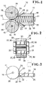
- the crimping apparatus 10 comprises a pair of upper and lower rolls 11, 12 cooperating in excerting pressure on textile fibrous materials 13 passing therebetween along a longitudinal path, and a stuffing box 14 disposed downstream of and adjacent to the rolls 11, 12 for crimping the textile fibrous materials 13 supplied therein by the rolls 11, 12.
- the textile fibrous materials 13 to be crimped include filaments, yarns, tows for staple fibers and the like.
- the lower roll 12 is fixedly mounted on a shaft 15 adapted to be driven by a suitable drive means (not shown) to rotate the roll 12 at a predetermined peripheral speed.
- the upper roll 11 is rotatably mounted on a shaft 16 which is movably supported for vertical movement toward and away from the shaft 15 to adjust a nipping clearance 17 between the rolls 11, 12.
- the stuffing box 14 is in the form of a substantially hollow rectangular box with opposite ends open for the passage therethrough of the textile fibrous materials 13.
- the box 14 is composed of a pair of upper and lower doctor blades 18, 19 and a pair of side plates 20, 21 disposed one on each side of the superposed doctor blades 18, 19 to define jointly therewith a stuffing chamber 22.
- Each of the doctor blades 18, 19 has, at one end adjacent to a corresponding one of the rolls 11, 12, an arcuate end surface 23 complementary in contour with the peripheral surface of the corresponding roll 11, 12 and facing to the same with an arcuate clearance 24 therebetween.
- each doctor blade 18, 19 jointly define a knife-edge 26 which serves to scrape the textile fibrous materials 13 off the peripheral surface of the respective roll 11, 12 while the latter is rotated.
- the lower doctor blade 19 is fixed in position while the upper doctor blade 18 is movable in both horizontal and vertical directions so as to keep the arcuate clearance 24 constant when the upper roll 11 is vertically displaced with respact to the lower roll 12.
- the side plates 20, 21 are secured to opposite side surfaces of the stationary lower doctor blade 19 with clearances 27 therebetween.
- the side plates 20, 21 may be sealingly connected to the side surfaces of the lower doctor plate 19.
- Each side plate 20, 21 has a tapered extension 28 projecting beyond the end surface 23 of the doctor blade 18, 19 and having an inner surface 28' extending parallel to one of opposite end surfaces 29 of the respective rolls 10, 11 with a clearance 30 therebetween.
- the inner surface 28' has a pair of arcuate peripheral portions 31, 31 confronting to opposed inner peripheral portions of corresponding ones of the end surfaces 23 and blending together over the nipping clearance 17 between the rolls 11, 12.
- the clearances 30 and the arcuate clearances . 24 jointly constitute a substantially annular clearance surrounding the opposite inner peripheral portions of the rolls 11, 12.
- the upper doctor blade 18 has a transversely extending through-hole 32 adjacent to the arcuate end surface 23, a blind-hole 33 communicating at one end with the through-hole 31 and having another end adapted to be connected to a source (not shown ) for supplying a pressurized fluid, and a transversely extending slot 34 opening at one side to the arcuate end surface 23 along the length thereof and at the other side to the through-hole 31.
- the doctor blade 18 may be provided with a series of orifices 35 instead of the slot 34, each of the orifices 35 opening at one end to the arcuate end surface 23 and the opposite end to the through-hole 32.
- a stream of pressurized fluid supplied by the source flows through the holes 33, 32 and the slot 34 or the orifices 35 into the arcuate clearance 24.
- the slot 34 (and also the orifices 35 not shown) is spaced from the knife-edge 26 at a distance substasntially equal to or smaller than one-third of the width of the arcuate end surface 23 so that the stream of pressurized fluid can flow mostly into the interior of the stuffing-box 14 along the peripheral surface of the roll 11, thereby enhancing scraping effect of the knife-edge 26.
- the textile fibrous materials 13 are prevented from wedging into the clearance 24 while they are fed by the rolls 11, 12 into the stuffing box 14 even at a speed of 1000 m/min.
- the pressurized fluid then flows downstream of the stuffing chamber 22 through the textile fibrous materials 13 crimped therein and escapes from the stuffing box 14.
- the pressurized fluid can pass smoothly through the stuffing chamber 22 without increasing the pressure in the stuffing box 14. Since the lower doctor blade 19 is a mirrorimage of and functionally the same as the upper doctor blade 18, no explanation thereon is needed.
- each of the side plates 20, 21 has a respective through-hole 36 opening at one end to the clearance 27 and having an another end adapted to be connected to the source of pressurized fluid.
- a stream of pressurized fluid supplied through the through-hole 36 into the respective clearance 27 also prevents the textile fibrous materials 13 from entering into the clearance 27 while the latter is crimped in the stuffing-box 14.
- the through-hole 36 is disposed closely to the knife-edge 26 and is spaced from the general plane of the inner surface 25 of the doctor blade 18 by a distance which is substantially equal to or smaller than one-third of the width of the side surface of the doctor blade 18.
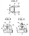
- Modified side plates 38, 38 are shown in FIGS. 5 and 6 each have a channel 39 for the passage therethrough of a stream of pressurized fluid.
- the channel 39 has a pair of outlets 40, 40 respectively opening to a pair of arcuate peripheral portions 41, 41 of the inner surface 42 of each side plate 38.
- the outlets 40, 40 are disposed one on each side of the nipping clearance 17 and each spaced from a respective inner edge of the peripheral portion 41 by a distance which is substantially equal to or smaller than one-third of the width of the peripheral portion 41.
- the channel 39 has an outlet opening to the outside of the side plate 38 for fluid communication with a source (not shown ) of a pressurized fluid.
- Each side plate 38 has a blind-hole 43 opening at one end to the inner surface 42 and communicating at the opposite end with the channel 39.
- the blind-hole 43 is functionally the same as the through-hole shown in FIGS. 3 - 6 at the numeral 36.
- a modified side plate 44 includes a base member 45, and a jacket member 46 mounted on the base member 45.
- the jacket member 46 has an enlarged head 47 and a stem 48 extending perpendicular to the head 47.
- the head 47 has a shape substantially the same as the shape of the converging end portion of the side plate 38 shown in FIG. 6,iand the stem 48 extends through a hole in a bracket 49 secured to the base member 45.
- a compression spring 50 fits over the stem 48 and is disposed between the bracket 49 and the head 47 to urge the latter to the rolls' end surfaces 29, 29.
- a channel 51 extends continuously through the head 47 and the stem 48 and has at one end a pair of outlets 52 (only one shown) opening respectively to a pair of arcuate peripheral portions of an inner surface of said head 47.
- the outlets 52 are disposed one on each side of the nipping clearance 17 and each spaced from a respective inner edge of each peripheral portion by a distance substantially equal to or smaller than one-third of the width of said peripheral portion. Streams of pressurized fluid injected from the outlets 52 form a thin layer of the pressurized fluid between the opposed surfaces of the head 47 and the rolls 11, 12 so that the the head 47 and the rolls 11, 12 are prevented from being worn away at the opposed surfaces.
- FIG. 9 shows another jacket member 53 similar to the one shown in FIG. 8 at 46 but different therefrom in that the jacket member 53 is mounted to a base member 54 by means of a bolt-and-double nut connection 55 which serves to adjust a clearance between the inner surface of a head 56 and end surfaces 29 of the rolls 11, 12.
Landscapes
- Engineering & Computer Science (AREA)
- Mechanical Engineering (AREA)
- Textile Engineering (AREA)
- Yarns And Mechanical Finishing Of Yarns Or Ropes (AREA)
Applications Claiming Priority (2)
| Application Number | Priority Date | Filing Date | Title |
|---|---|---|---|
| JP16804482A JPS5959931A (ja) | 1982-09-27 | 1982-09-27 | 高速圧充函式捲縮付与機 |
| JP168044/82 | 1982-09-27 |
Publications (2)
| Publication Number | Publication Date |
|---|---|
| EP0108705A2 true EP0108705A2 (fr) | 1984-05-16 |
| EP0108705A3 EP0108705A3 (en) | 1986-03-12 |
Family
ID=15860778
Family Applications (1)
| Application Number | Title | Priority Date | Filing Date |
|---|---|---|---|
| EP83730091A Withdrawn EP0108705A3 (en) | 1982-09-27 | 1983-09-27 | Apparatus for crimping textile fibrous materials |
Country Status (3)
| Country | Link |
|---|---|
| EP (1) | EP0108705A3 (fr) |
| JP (1) | JPS5959931A (fr) |
| CA (1) | CA1243831A (fr) |
Cited By (4)
| Publication number | Priority date | Publication date | Assignee | Title |
|---|---|---|---|---|
| EP0139832A3 (en) * | 1983-09-08 | 1986-03-05 | Neumunstersche Maschinen- Und Apparatebau Gesellschaft Mbh. (Neumag) | Stuffer box crimping apparatus |
| US4662042A (en) * | 1986-04-07 | 1987-05-05 | Celanese Corporation | Methods and apparatus for lubricating a cheek plate of a textile crimping mechanism |
| EP1798319A1 (fr) * | 2005-12-19 | 2007-06-20 | Sergio Zamattio | Procédé de gonflage d'une bande de matériau textile, dispositif associé et bande de matériau textile obtenue de la sorte |
| CN113166981A (zh) * | 2018-12-04 | 2021-07-23 | 欧瑞康纺织有限及两合公司 | 用于运行卷曲设备的方法和卷曲设备 |
Families Citing this family (1)
| Publication number | Priority date | Publication date | Assignee | Title |
|---|---|---|---|---|
| CA2185732A1 (fr) * | 1995-11-13 | 1997-05-14 | Man-Jun Yoo | Capsule pour bouteille et procede de fabrication d'une telle capsule |
Family Cites Families (5)
| Publication number | Priority date | Publication date | Assignee | Title |
|---|---|---|---|---|
| US2862279A (en) * | 1956-04-10 | 1958-12-02 | Allied Chem | Tow crimping apparatus |
| US3545058A (en) * | 1967-10-17 | 1970-12-08 | Techniservice Corp | Stuffer crimper with cooling fluid wretreatment means |
| US3618183A (en) * | 1970-02-11 | 1971-11-09 | Monsanto Co | Insert pressure controller |
| US3978561A (en) * | 1973-06-01 | 1976-09-07 | Indian Head Inc. | Apparatus for texturing continuous filament yarn |
| GB1571521A (en) * | 1976-11-25 | 1980-07-16 | Vepa Ag | Apparatus for crimping synthetic yarns and the like |
-
1982
- 1982-09-27 JP JP16804482A patent/JPS5959931A/ja active Granted
-
1983
- 1983-09-26 CA CA000437508A patent/CA1243831A/fr not_active Expired
- 1983-09-27 EP EP83730091A patent/EP0108705A3/en not_active Withdrawn
Cited By (4)
| Publication number | Priority date | Publication date | Assignee | Title |
|---|---|---|---|---|
| EP0139832A3 (en) * | 1983-09-08 | 1986-03-05 | Neumunstersche Maschinen- Und Apparatebau Gesellschaft Mbh. (Neumag) | Stuffer box crimping apparatus |
| US4662042A (en) * | 1986-04-07 | 1987-05-05 | Celanese Corporation | Methods and apparatus for lubricating a cheek plate of a textile crimping mechanism |
| EP1798319A1 (fr) * | 2005-12-19 | 2007-06-20 | Sergio Zamattio | Procédé de gonflage d'une bande de matériau textile, dispositif associé et bande de matériau textile obtenue de la sorte |
| CN113166981A (zh) * | 2018-12-04 | 2021-07-23 | 欧瑞康纺织有限及两合公司 | 用于运行卷曲设备的方法和卷曲设备 |
Also Published As
| Publication number | Publication date |
|---|---|
| CA1243831A (fr) | 1988-11-01 |
| EP0108705A3 (en) | 1986-03-12 |
| JPH0210245B2 (fr) | 1990-03-07 |
| JPS5959931A (ja) | 1984-04-05 |
Similar Documents
| Publication | Publication Date | Title |
|---|---|---|
| US5025538A (en) | Apparatus for crimping tow including stuffer box, crimping rollers and molding rollers | |
| JP4135823B2 (ja) | 製紙機械のヘッドボックス | |
| EP0108705A2 (fr) | Appareil à friser des matières textiles fibreuses | |
| EP0679743B1 (fr) | Dispositif et procédé pour friser des fibres destinées à la production d'étoffes non tissées | |
| EP2013411B1 (fr) | Procede de raffinage d'un fil ou d'un ruban | |
| EP0123072A1 (fr) | Tuyère de texturation de fil | |
| KR0165862B1 (ko) | 초지기트윈와이어포머 및 그 탈수기기 | |
| US4809405A (en) | Apparatus for compressing and automatically introducing a textile fibre strand into a feed nip | |
| JPH02112431A (ja) | 空気噴射式テクスチヤード加工機で糸を湿らせるための方法及び装置 | |
| US4797979A (en) | Arrangement for supplying a fiber processing machine | |
| DE19544882A1 (de) | Bahnabnahmevorrichtung | |
| US6141843A (en) | Apparatus and method for stuffer box crimping a synthetic yarn | |
| GB2128644A (en) | Air nozzle for producing knot-shaped entanglements in running multifilament yarns | |
| US20060005365A1 (en) | Method and apparatus for stuffer box crimping a multifilament yarn | |
| CA1243830A (fr) | Appareil pour gaufrer des matieres textiles fibreuses | |
| US3881308A (en) | Sliver condenser for a fiber separating device of open-end spinning units | |
| GB1457667A (en) | Headbox for paper-making machines | |
| EP1025297B1 (fr) | Jet gonflant a impact unique | |
| EP1936026A1 (fr) | Partie humide pour une machine destinée à la fabrication de bandes de matière fibreuse, en particulier machine à papier destinée à la fabrication de papier sans bois | |
| US4765042A (en) | Apparatus for texturing continuous filamentary tow | |
| US5882482A (en) | Convergent flow headbox | |
| US4163306A (en) | Bounce crimper outlet apparatus | |
| US3225415A (en) | Defect responsive apparatus | |
| US6000101A (en) | Textile processing machine having pneumatic pressure-generating means | |
| DE3440975A1 (de) | Verfahren und vorrichtung zum kraeuseln von kabeln aus synthetischen faeden |
Legal Events
| Date | Code | Title | Description |
|---|---|---|---|
| PUAI | Public reference made under article 153(3) epc to a published international application that has entered the european phase |
Free format text: ORIGINAL CODE: 0009012 |
|
| AK | Designated contracting states |
Designated state(s): DE GB IT |
|
| PUAL | Search report despatched |
Free format text: ORIGINAL CODE: 0009013 |
|
| AK | Designated contracting states |
Kind code of ref document: A3 Designated state(s): DE GB IT |
|
| STAA | Information on the status of an ep patent application or granted ep patent |
Free format text: STATUS: THE APPLICATION IS DEEMED TO BE WITHDRAWN |
|
| 18D | Application deemed to be withdrawn |
Effective date: 19861113 |
|
| RIN1 | Information on inventor provided before grant (corrected) |
Inventor name: TANI, HARUHISA Inventor name: OKADA, TOKIO Inventor name: KOJIMA, SHIGEZO |