EP0108717A2 - Dispositif pour nettoyer des eaux usées - Google Patents
Dispositif pour nettoyer des eaux usées Download PDFInfo
- Publication number
- EP0108717A2 EP0108717A2 EP83810485A EP83810485A EP0108717A2 EP 0108717 A2 EP0108717 A2 EP 0108717A2 EP 83810485 A EP83810485 A EP 83810485A EP 83810485 A EP83810485 A EP 83810485A EP 0108717 A2 EP0108717 A2 EP 0108717A2
- Authority
- EP
- European Patent Office
- Prior art keywords
- rake
- plastic band
- plastic
- slots
- drivers
- Prior art date
- Legal status (The legal status is an assumption and is not a legal conclusion. Google has not performed a legal analysis and makes no representation as to the accuracy of the status listed.)
- Granted
Links
- 238000004140 cleaning Methods 0.000 title claims description 3
- 239000010865 sewage Substances 0.000 title description 2
- 239000004033 plastic Substances 0.000 claims abstract description 60
- 230000001681 protective effect Effects 0.000 claims abstract description 12
- 230000000630 rising effect Effects 0.000 claims abstract description 7
- 239000002351 wastewater Substances 0.000 claims description 3
- XLYOFNOQVPJJNP-UHFFFAOYSA-N water Substances O XLYOFNOQVPJJNP-UHFFFAOYSA-N 0.000 abstract description 17
- 239000004576 sand Substances 0.000 abstract description 8
- 239000000969 carrier Substances 0.000 abstract description 3
- 238000011109 contamination Methods 0.000 abstract 1
- 238000012216 screening Methods 0.000 description 3
- 229920000742 Cotton Polymers 0.000 description 2
- 239000002184 metal Substances 0.000 description 2
- 235000010585 Ammi visnaga Nutrition 0.000 description 1
- 244000153158 Ammi visnaga Species 0.000 description 1
- ATJFFYVFTNAWJD-UHFFFAOYSA-N Tin Chemical compound [Sn] ATJFFYVFTNAWJD-UHFFFAOYSA-N 0.000 description 1
- 230000029087 digestion Effects 0.000 description 1
- 239000013013 elastic material Substances 0.000 description 1
- 239000012535 impurity Substances 0.000 description 1
- 229920000136 polysorbate Polymers 0.000 description 1
Images

Classifications
-
- E—FIXED CONSTRUCTIONS
- E02—HYDRAULIC ENGINEERING; FOUNDATIONS; SOIL SHIFTING
- E02B—HYDRAULIC ENGINEERING
- E02B8/00—Details of barrages or weirs ; Energy dissipating devices carried by lock or dry-dock gates
- E02B8/02—Sediment base gates; Sand sluices; Structures for retaining arresting waterborne material
- E02B8/023—Arresting devices for waterborne materials
- E02B8/026—Cleaning devices
-
- B—PERFORMING OPERATIONS; TRANSPORTING
- B01—PHYSICAL OR CHEMICAL PROCESSES OR APPARATUS IN GENERAL
- B01D—SEPARATION
- B01D33/00—Filters with filtering elements which move during the filtering operation
- B01D33/04—Filters with filtering elements which move during the filtering operation with filtering bands or the like supported on cylinders which are impervious for filtering
-
- B—PERFORMING OPERATIONS; TRANSPORTING
- B01—PHYSICAL OR CHEMICAL PROCESSES OR APPARATUS IN GENERAL
- B01D—SEPARATION
- B01D33/00—Filters with filtering elements which move during the filtering operation
- B01D33/70—Filters with filtering elements which move during the filtering operation having feed or discharge devices
Definitions
- the present invention relates to a rake for cleaning waste water, the rake being arranged in an inlet channel.
- the invention has for its object to eliminate the disadvantages of the known and to create a rake of the type mentioned, which can function as a fine rake, it does not cause significant water retention and thus also significantly reduces the deposit of the sand in front of the computer system.
- the above-mentioned object is achieved in that the rake has a flat part that extends the bottom of the inlet channel and a rising part.
- the advantage of the invention is that the water can flow down through the flat part of the rake, the length of this flat part and the number and size of the openings in the rake of the through flow rate is adjusted.
- the rising part of the screen then serves to remove larger parts of the screenings.
- the rake is equipped with a circumferential plastic belt provided with slots and drivers.
- This embodiment has several advantages.
- the diameter of the lower roller can be kept significantly smaller than when using metal strips or metal braids, which in turn brings significant advantages on site.
- the plastic band is provided with slots that allow sufficient flow and with drivers that larger parts, such as Stones and branches can be transported upwards.
- the plastic band consists of segments, the end parts of which are bent outwards and assembled to one another and form the drivers for coarse parts.
- the drivers are produced in a simple manner directly as components of the individual segments. These drivers also have slots.
- the plastic band is mounted around a lower roller and an upper roller, the upper roller having cams, the shape and mutual position of which correspond to the shape and the mutual position of the slots in the plastic band.
- the cams of the upper roller engage in the slots of the plastic band during operation of the rake and thus press the dirt adhering therein and possibly the ice out of the plastic band. This embodiment also ensures that computing is suitable at low temperatures.
- the longitudinal edges of the plastic band are expediently connected by means of connecting parts to a chain, which are each at least partially supported in a sliding guide.
- a chain which are each at least partially supported in a sliding guide.
- the chains also ensure that the plastic band does not buckle due to the load of water and dirt. It is also sufficient if the sliding guides are arranged only for the part of the plastic band moving in the flow direction, at least in the flat part of the rake.
- the upper roller provided with the cams is mechanically connected to the upper sprockets and connected to the geared motor.
- the upper roller provided with the cams is thus driven together with the upper sprockets, this upper part being easily accessible with the geared motor.
- a water-permeable, roof-shaped protective part is arranged in the longitudinal direction of the flat part at least in the flat part of the rake between the upper and the lower part of the plastic band.
- This roof-shaped protective part is provided with openings that are significantly smaller than the slots of the plastic band.
- This protective part laterally discharges any objects that may have fallen through the slots, so that the inner surface of the lower part of the plastic band is not burdened with these objects. This would be Otherwise, they are guided in the direction under the lower roller and possibly jammed there.
- the rake is advisable to provide with at least one scraper, which contacts both the plastic belt and the drivers during the circulation of the plastic belt.
- the plastic tape is smooth so that most of the dirt on the back automatically falls off.
- the slots are cleaned using the cams.
- some parts can adhere to the plastic band, especially with ice. In this case they are removed with the scraper.
- a rake A, B is stored in an inlet channel 1.
- the bottom of the inlet channel 1 is designated by the reference number 24.
- a deeper part 25 of the bottom of the inlet channel 1 follows in the flow direction of the water.
- a flat part A of the rake is arranged so that its upper surface extends as an extension of the bottom 24 of the inlet channel 1.
- the small distance - tween the foremost part of the rake and the bottom 24 of the inlet channel 1 is bridged with a rubber flap.
- a plastic band 3 is provided with slots that are not visible in this drawing.
- the plastic band 3 consists of segments 3 '. The connecting parts of these segments 3 'form carriers 6.
- the plastic band 3 is guided around a lower roller 5 and an upper roller 12.
- the lower roller 5 has a very small diameter.
- the upper roller 12 will be described in detail later.
- Both rollers 5 and 12 are rotatably supported between two side plates 9.
- a first deflection sprocket 13 and a second deflection sprocket 14 are arranged between the flat part A and the rising part B of the rake.
- a water-permeable, roof-shaped protective part 16 is arranged between the upper part of the plastic band 3 and its lower part. In this example, this roof-shaped protective part 16 extends both in the flat part A and in the rising part B of the rake.
- a funnel 17 is connected in its upper part, under which a basket 22 is arranged.
- This basket 22 stands on the upper edge 23 of the inlet channel 1.
- a scraper 18 is located inside the funnel 17. This scraper 18 is fastened on a two-armed lever 19, the other end of the lever 19 carrying a counterweight 20.
- this wiper 18 is shown only in a simplified manner. The position of the scraper 18 is fully drawn, in which it first touches a driver 6. The lowermost position of the scraper 18 is drawn in dashed lines, where the scraper 18 has already reached the outer end of the driver 6. This position is designated by the reference number 21.
- the water 26, possibly with sand, is only shown schematically. It can be seen from FIG. 1 that the water 26 flows first above the bottom 24 and then via the rubber flap 2 onto the surface of the plastic strip 3.
- Figure 2 shows the upper part B of the rake. Most of the components have already been described with reference to FIG. 1. In Figure 2 you can also see the slots 4, which are, however, shown in this drawing only simplified as lines and are of course carried out in the entire surface of the plastic tape 3.
- the plastic guides 8 are attached to the side plates 9 and in them the chains 7 are carried, which carry the plastic band 3.
- the upper roller 12 is provided on both sides with chain wheels 11 and coupled to the geared motor 10.
- the flat part A of the rake is also shown schematically.
- the lower roller 5 is partially covered with the rubber flap 2, which forms the connection to the bottom 24 of the inlet channel 1.
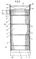
- Figure 3 shows a simplified section through the flat part A of the rake and the inlet channel 1.
- the side plates 9 are mounted directly on the side walls of the inlet channel 1. They carry the slide guides 8 for the chains 7. These slide guides 8 are made of plastic and also serve as seals between the plastic band 3 and the side plates 9. No slide guides 8 are attached to the lower side of the plastic band 3, so that the water 26 can possibly be mixed with the Sand can flow sideways without obstacle.
- the plastic tape 3 is on both of its edges connected to the chains 7 by means of connecting parts 7 '.
- the slots 4 are also clearly visible. In the plastic band 3 we see these slots 4 in section, in the drivers 6 in view.
- a roof-shaped protective part 16 is arranged between the upper and the lower part of the plastic band 3. Although this protective part 16 is permeable to water, its openings are, however, significantly smaller than the openings of the slots 4. As can be seen from FIG come from where they are transported due to the flow of water.
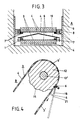
- FIG. 4 shows a section of the upper roller 12 with part of the plastic strip 3.
- the upper roller 12 is placed on a shaft 12 ', this shaft 12' being coupled to the geared motor 10, which also drives the chain wheels 11.
- the surface of the upper roller 12 is provided with cams 15 which are designed as teeth and whose dimensions and mutual position correspond to the dimensions and the mutual position of the slots 4 of the plastic band 3. During the operation of the rake, these cams 15 penetrate into the slots 4 and displace the dirt and / or ice which may be stuck therein.
- a scraper 18 is provided which strips off the surface of the plastic strip 3 and the functional surface of the drivers 6.
- the position of the scraper 18 is fully drawn, in which it touches a scraper 6 for the first time. With the further movement of the plastic strip 3 downward, the scraper 18 moves to the outer end of the driver 6. This position is shown in dashed lines and provided with the reference number 21.
- the scraper 18 is made of an elastic material. It can be arranged in a tiltable manner and provided with a counterweight 20, as was shown in FIG. 1 de. It can also be designed differently, for example it can be held in a resilient mounting. If this is expedient, several wipers 18 can also be arranged one behind the other.
Landscapes
- Chemical & Material Sciences (AREA)
- Chemical Kinetics & Catalysis (AREA)
- Engineering & Computer Science (AREA)
- General Engineering & Computer Science (AREA)
- Mechanical Engineering (AREA)
- Civil Engineering (AREA)
- Structural Engineering (AREA)
- Separation, Recovery Or Treatment Of Waste Materials Containing Plastics (AREA)
- Biological Treatment Of Waste Water (AREA)
- Centrifugal Separators (AREA)
- Aeration Devices For Treatment Of Activated Polluted Sludge (AREA)
- Removal Of Specific Substances (AREA)
- Detergent Compositions (AREA)
- Organic Low-Molecular-Weight Compounds And Preparation Thereof (AREA)
Priority Applications (1)
| Application Number | Priority Date | Filing Date | Title |
|---|---|---|---|
| AT83810485T ATE22714T1 (de) | 1982-11-05 | 1983-10-21 | Vorrichtung zur reinigung von abwasser. |
Applications Claiming Priority (2)
| Application Number | Priority Date | Filing Date | Title |
|---|---|---|---|
| CH643882 | 1982-11-05 | ||
| CH6438/82 | 1982-11-05 |
Publications (3)
| Publication Number | Publication Date |
|---|---|
| EP0108717A2 true EP0108717A2 (fr) | 1984-05-16 |
| EP0108717A3 EP0108717A3 (en) | 1984-06-13 |
| EP0108717B1 EP0108717B1 (fr) | 1986-10-08 |
Family
ID=4309639
Family Applications (1)
| Application Number | Title | Priority Date | Filing Date |
|---|---|---|---|
| EP83810485A Expired EP0108717B1 (fr) | 1982-11-05 | 1983-10-21 | Dispositif pour nettoyer des eaux usées |
Country Status (3)
| Country | Link |
|---|---|
| EP (1) | EP0108717B1 (fr) |
| AT (1) | ATE22714T1 (fr) |
| DE (1) | DE3366722D1 (fr) |
Cited By (6)
| Publication number | Priority date | Publication date | Assignee | Title |
|---|---|---|---|---|
| WO1987002595A1 (fr) * | 1985-10-31 | 1987-05-07 | Hans Eriksson | Procede d'epuration d'eau et utilisation de celui-ci |
| EP0282906A3 (en) * | 1987-03-17 | 1988-12-07 | Bernhard Kessel | Grease separator |
| WO1991008819A1 (fr) * | 1989-12-08 | 1991-06-27 | Austevoll Oystein | Ensemble de filtres |
| FR2715085A1 (fr) * | 1994-01-20 | 1995-07-21 | Egretier Jean Michel | Dégrilleur autonettoyant à courroies. |
| WO2013124662A1 (fr) * | 2012-02-22 | 2013-08-29 | Anglian Water Services Limited | Système de tamisage d'eaux d'égout |
| CN106006769A (zh) * | 2016-05-30 | 2016-10-12 | 海乐分离设备工程(无锡)有限公司 | 回转式耙式格栅除污机 |
Family Cites Families (6)
| Publication number | Priority date | Publication date | Assignee | Title |
|---|---|---|---|---|
| DE1250409B (de) * | 1967-09-21 | H R Black Company Detroit, Mich (V St A) | Abdichtungsanordnung fur em kontinuierlich umlaufendes Filter band | |
| DE801626C (de) * | 1949-07-20 | 1951-01-18 | Franz Schaefer | Mechanische Reinigungsvorrichtung fuer Wasser |
| FR1090784A (fr) * | 1953-10-24 | 1955-04-04 | Riomilex | Procédé et machines de nettoyage de récipients tels que bouteilles portant des étiquettes |
| FR1352960A (fr) * | 1963-01-09 | 1964-02-21 | Appareil automatique d'épuration des eaux usées chargées de matières gluantes | |
| US3464563A (en) * | 1967-02-06 | 1969-09-02 | American Air Filter Co | Liquid filter apparatus |
| FR2285935A1 (fr) * | 1974-09-30 | 1976-04-23 | Penarroya Miniere Metall | Dispositif de degrillage |
-
1983
- 1983-10-21 DE DE8383810485T patent/DE3366722D1/de not_active Expired
- 1983-10-21 EP EP83810485A patent/EP0108717B1/fr not_active Expired
- 1983-10-21 AT AT83810485T patent/ATE22714T1/de not_active IP Right Cessation
Cited By (10)
| Publication number | Priority date | Publication date | Assignee | Title |
|---|---|---|---|---|
| WO1987002595A1 (fr) * | 1985-10-31 | 1987-05-07 | Hans Eriksson | Procede d'epuration d'eau et utilisation de celui-ci |
| EP0282906A3 (en) * | 1987-03-17 | 1988-12-07 | Bernhard Kessel | Grease separator |
| WO1991008819A1 (fr) * | 1989-12-08 | 1991-06-27 | Austevoll Oystein | Ensemble de filtres |
| US5300221A (en) * | 1989-12-08 | 1994-04-05 | Oystein Austevoll | Filter arrangement |
| FR2715085A1 (fr) * | 1994-01-20 | 1995-07-21 | Egretier Jean Michel | Dégrilleur autonettoyant à courroies. |
| WO2013124662A1 (fr) * | 2012-02-22 | 2013-08-29 | Anglian Water Services Limited | Système de tamisage d'eaux d'égout |
| GB2499728B (en) * | 2012-02-22 | 2015-03-18 | Anglian Water Services Ltd | Sewage screening system |
| AU2013223797B2 (en) * | 2012-02-22 | 2017-02-16 | Anglian Water Services Limited | Sewage screening system |
| CN106006769A (zh) * | 2016-05-30 | 2016-10-12 | 海乐分离设备工程(无锡)有限公司 | 回转式耙式格栅除污机 |
| CN106006769B (zh) * | 2016-05-30 | 2023-09-29 | 江苏如克环保设备有限公司 | 回转式耙式格栅除污机 |
Also Published As
| Publication number | Publication date |
|---|---|
| DE3366722D1 (en) | 1986-11-13 |
| ATE22714T1 (de) | 1986-10-15 |
| EP0108717B1 (fr) | 1986-10-08 |
| EP0108717A3 (en) | 1984-06-13 |
Similar Documents
| Publication | Publication Date | Title |
|---|---|---|
| DE69202597T2 (de) | Kompakte Vorrichtung zur Entwässerung und zum Ausdrücken von Schlämmen. | |
| DE2330915A1 (de) | Verfahren und vorrichtung zum ausscheiden von feststoffen aus fluessigkeiten | |
| DE1634031A1 (de) | Rechen mit Reinigungsvorrichtung | |
| DE1950710C3 (de) | Rechen zur Reinigung von in einem Kanal strömenden Flüssigkeiten | |
| DE1962110A1 (de) | Selbstfahrender Maehdrescher mit Axialdreschtrommel und ihr nachfolgender Reinigungsvorrichtung | |
| DE1903566A1 (de) | Raupenfahrzeug | |
| DE19519088C1 (de) | Entmistungsvorrichtung für einen Viehstall mit mechanisch geräumten Mistaufnahmekanälen | |
| DE2654475A1 (de) | Rechenanlage | |
| DE2248861A1 (de) | Rechenreinigungsvorrichtung | |
| EP0108717A2 (fr) | Dispositif pour nettoyer des eaux usées | |
| DE1757697B1 (de) | Vorrichtung zum Trennen von Rueben und Steinen auf trockenem Wege | |
| DE2521166A1 (de) | Maschine zum reinigen von gemuesewurzeln oder -knollen | |
| DE2721125C3 (de) | Mehrreihige Rübenerntemaschine mit Rodescharen und Reinigungswalzen | |
| DE2401956A1 (de) | Selbstreinigende filtervorrichtung zur kontinuierlichen beseitigung von festkoerpern aus einem fluessigkeitsstrom | |
| DE3003827A1 (de) | Einrichtung zur mechanischen reinigung von waessern vermittels von rechen | |
| DE202018106890U1 (de) | Einrichtung zur Abwasserreinigung | |
| DE69416434T2 (de) | Kranktrennvorrichtung für Kartoffeln oder Rüben | |
| DE2700481C2 (de) | Förderer für Schüttgut | |
| DE102008063969B3 (de) | Aufnahmegerät | |
| DE2749558B2 (de) | Kartoffel-Sammelerntemaschine | |
| DE19822853A1 (de) | Vorrichtung zum schonenden Abtrennen von Wasserlebewesen aus Wasserläufen | |
| DE1961636B2 (de) | Sortiervorrichtung | |
| DE1217692B (de) | Batteriekaefig | |
| DE3037326A1 (de) | Verfahren und vorrichtung zur entwaesserung von schlaemmen | |
| DE2123095C3 (de) | Vorrichtung zum Abscheiden von Wasser beim Spulen von Hackfrüchten, insbesondere von Rüben, und Verwendung der Vorrichtung als Waschvorrichtung |
Legal Events
| Date | Code | Title | Description |
|---|---|---|---|
| PUAI | Public reference made under article 153(3) epc to a published international application that has entered the european phase |
Free format text: ORIGINAL CODE: 0009012 |
|
| PUAL | Search report despatched |
Free format text: ORIGINAL CODE: 0009013 |
|
| AK | Designated contracting states |
Designated state(s): AT BE CH DE FR GB IT LI LU NL SE |
|
| AK | Designated contracting states |
Designated state(s): AT BE CH DE FR GB IT LI LU NL SE |
|
| 17P | Request for examination filed |
Effective date: 19840616 |
|
| ITF | It: translation for a ep patent filed | ||
| GRAA | (expected) grant |
Free format text: ORIGINAL CODE: 0009210 |
|
| AK | Designated contracting states |
Kind code of ref document: B1 Designated state(s): AT BE CH DE FR GB IT LI LU NL SE |
|
| REF | Corresponds to: |
Ref document number: 22714 Country of ref document: AT Date of ref document: 19861015 Kind code of ref document: T |
|
| REF | Corresponds to: |
Ref document number: 3366722 Country of ref document: DE Date of ref document: 19861113 |
|
| ET | Fr: translation filed | ||
| PLBE | No opposition filed within time limit |
Free format text: ORIGINAL CODE: 0009261 |
|
| STAA | Information on the status of an ep patent application or granted ep patent |
Free format text: STATUS: NO OPPOSITION FILED WITHIN TIME LIMIT |
|
| 26N | No opposition filed | ||
| REG | Reference to a national code |
Ref country code: GB Ref legal event code: 732 |
|
| REG | Reference to a national code |
Ref country code: CH Ref legal event code: PUE Owner name: ALPHA AG |
|
| REG | Reference to a national code |
Ref country code: FR Ref legal event code: TP |
|
| ITTA | It: last paid annual fee | ||
| PGFP | Annual fee paid to national office [announced via postgrant information from national office to epo] |
Ref country code: GB Payment date: 19920818 Year of fee payment: 10 |
|
| PG25 | Lapsed in a contracting state [announced via postgrant information from national office to epo] |
Ref country code: GB Effective date: 19931021 |
|
| EPTA | Lu: last paid annual fee | ||
| GBPC | Gb: european patent ceased through non-payment of renewal fee |
Effective date: 19931021 |
|
| PGFP | Annual fee paid to national office [announced via postgrant information from national office to epo] |
Ref country code: LU Payment date: 19941001 Year of fee payment: 12 |
|
| PGFP | Annual fee paid to national office [announced via postgrant information from national office to epo] |
Ref country code: AT Payment date: 19941025 Year of fee payment: 12 |
|
| PGFP | Annual fee paid to national office [announced via postgrant information from national office to epo] |
Ref country code: BE Payment date: 19941028 Year of fee payment: 12 |
|
| PGFP | Annual fee paid to national office [announced via postgrant information from national office to epo] |
Ref country code: NL Payment date: 19941031 Year of fee payment: 12 |
|
| EAL | Se: european patent in force in sweden |
Ref document number: 83810485.9 |
|
| PGFP | Annual fee paid to national office [announced via postgrant information from national office to epo] |
Ref country code: SE Payment date: 19950929 Year of fee payment: 13 |
|
| PGFP | Annual fee paid to national office [announced via postgrant information from national office to epo] |
Ref country code: FR Payment date: 19951013 Year of fee payment: 13 |
|
| PG25 | Lapsed in a contracting state [announced via postgrant information from national office to epo] |
Ref country code: LU Free format text: LAPSE BECAUSE OF NON-PAYMENT OF DUE FEES Effective date: 19951021 Ref country code: AT Effective date: 19951021 |
|
| PG25 | Lapsed in a contracting state [announced via postgrant information from national office to epo] |
Ref country code: BE Effective date: 19951031 |
|
| PGFP | Annual fee paid to national office [announced via postgrant information from national office to epo] |
Ref country code: CH Payment date: 19951214 Year of fee payment: 13 |
|
| BERE | Be: lapsed |
Owner name: FUCHS MASCHINENBAU Effective date: 19951031 |
|
| PG25 | Lapsed in a contracting state [announced via postgrant information from national office to epo] |
Ref country code: NL Effective date: 19960501 |
|
| NLV4 | Nl: lapsed or anulled due to non-payment of the annual fee |
Effective date: 19960501 |
|
| PG25 | Lapsed in a contracting state [announced via postgrant information from national office to epo] |
Ref country code: SE Effective date: 19961022 |
|
| PG25 | Lapsed in a contracting state [announced via postgrant information from national office to epo] |
Ref country code: LI Effective date: 19961031 Ref country code: CH Effective date: 19961031 |
|
| PGFP | Annual fee paid to national office [announced via postgrant information from national office to epo] |
Ref country code: DE Payment date: 19961221 Year of fee payment: 14 |
|
| REG | Reference to a national code |
Ref country code: CH Ref legal event code: PL |
|
| PG25 | Lapsed in a contracting state [announced via postgrant information from national office to epo] |
Ref country code: FR Effective date: 19970630 |
|
| EUG | Se: european patent has lapsed |
Ref document number: 83810485.9 |
|
| REG | Reference to a national code |
Ref country code: FR Ref legal event code: ST |
|
| PG25 | Lapsed in a contracting state [announced via postgrant information from national office to epo] |
Ref country code: DE Free format text: LAPSE BECAUSE OF NON-PAYMENT OF DUE FEES Effective date: 19980701 |