EP0108722A1 - Manchon pour tuyaux - Google Patents
Manchon pour tuyaux Download PDFInfo
- Publication number
- EP0108722A1 EP0108722A1 EP83810503A EP83810503A EP0108722A1 EP 0108722 A1 EP0108722 A1 EP 0108722A1 EP 83810503 A EP83810503 A EP 83810503A EP 83810503 A EP83810503 A EP 83810503A EP 0108722 A1 EP0108722 A1 EP 0108722A1
- Authority
- EP
- European Patent Office
- Prior art keywords
- sleeves
- pipe
- sleeve
- connection device
- coupling body
- Prior art date
- Legal status (The legal status is an assumption and is not a legal conclusion. Google has not performed a legal analysis and makes no representation as to the accuracy of the status listed.)
- Granted
Links
Images
Classifications
-
- F—MECHANICAL ENGINEERING; LIGHTING; HEATING; WEAPONS; BLASTING
- F16—ENGINEERING ELEMENTS AND UNITS; GENERAL MEASURES FOR PRODUCING AND MAINTAINING EFFECTIVE FUNCTIONING OF MACHINES OR INSTALLATIONS; THERMAL INSULATION IN GENERAL
- F16L—PIPES; JOINTS OR FITTINGS FOR PIPES; SUPPORTS FOR PIPES, CABLES OR PROTECTIVE TUBING; MEANS FOR THERMAL INSULATION IN GENERAL
- F16L25/00—Construction or details of pipe joints not provided for in, or of interest apart from, groups F16L13/00 - F16L23/00
- F16L25/12—Joints for pipes being spaced apart axially
-
- F—MECHANICAL ENGINEERING; LIGHTING; HEATING; WEAPONS; BLASTING
- F16—ENGINEERING ELEMENTS AND UNITS; GENERAL MEASURES FOR PRODUCING AND MAINTAINING EFFECTIVE FUNCTIONING OF MACHINES OR INSTALLATIONS; THERMAL INSULATION IN GENERAL
- F16L—PIPES; JOINTS OR FITTINGS FOR PIPES; SUPPORTS FOR PIPES, CABLES OR PROTECTIVE TUBING; MEANS FOR THERMAL INSULATION IN GENERAL
- F16L47/00—Connecting arrangements or other fittings specially adapted to be made of plastics or to be used with pipes made of plastics
- F16L47/04—Connecting arrangements or other fittings specially adapted to be made of plastics or to be used with pipes made of plastics with a swivel nut or collar engaging the pipe
Definitions
- the invention relates to a pipe connecting device for connecting the regions of the latter adjacent to the facing ends of two pipe sections, wherein a sleeve which can be pushed on from the said ends is seated in each of these areas and a tubular coupling body surrounds the two sleeves.
- connection of the two pieces of pipe is releasable in a relatively simple manner, e.g. to be able to remove a piece of pipe that has become defective at any point from the pipeline and replace it with a new one.
- the pipe connection device according to the invention is preferably used for pipes made of non-metallic material, ie above all made of plastic, such as glass-fiber reinforced, thermosetting, in particular thermostatic material, for example Duro P last ( R ).
- Preferred embodiments of the pipe connection device according to the invention have one or more of the features described in the subclaims.
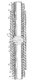
- the illustrated embodiment 10 of a pipe connection device connects the two pipe sections 12 and 14 to one another, between the mutually facing ends 12a and 14a of which a joint 11 remains.
- the pipe sections 12 and 14 can consist of plastic, in particular of fiber-reinforced, thermosetting high-pressure plastic.
- the connecting device 10 comprises a pair of plastic sleeves 16 and 18, which can also consist of fiber-reinforced, thermosetting plastic, the passage of which widens conically from one end of the sleeve to the other; the sleeves are connected, in particular glued, to correspondingly conically tapering regions of the pipe pieces 12, 14 in question, any suitable known composite material being used for gluing.
- the sleeves 16 and 18 have axially parallel, that is to say non-conically differing surfaces, and each of them has an annular groove in its surface which is adjacent to the one sleeve end, in which a sealing element, preferably an O-ring 20, 22 made of rubber or the like sealing material is inserted.
- the annular groove and the sealing element are preferably in or near that plane which extends transversely to the longitudinal axis of the pipe section 12, 14, in which the end 12a, 14a of the pipe section is located, on which the wall thickness of the latter is the smaller thanks to the conical tapering of the outer wall.
- the connecting device 10 further comprises an outer tubular coupling body 24, which can be made of fiber-reinforced plastic, which has been wound around a mandrel, in order to achieve a smooth inner wall 25.
- the clear width of the inner wall 25 is dimensioned such that the sleeves 16 and 18 can be easily inserted into and pulled out of the opposite open ends 24a and 24b of the coupling body 24, which the sealing elements 20 and 22 of the sleeves 16 and 18 on the inner wall 25 of the coupling body 24 lie sealingly.
- the end regions of the inner wall 25 of the coupling body 24 adjoining the opposite ends 24a, 24b of the coupling body 24 are provided with nut threads 26, 28 which preferably taper conically towards the inside of the coupling body.
- Tubular stop members 34, 36 which can be pushed onto the pipe sections 12, 14 and come to rest on the side of the sleeves 16, 18 facing away from the pipe section end 12a, 14a of the relevant pipe section 12, 14, have external threads 30, 32 on their outer walls on, which are chosen so that they can be screwed into the nut thread 26, 28 in the coupling body 24.
- These stop members 34, 36 which can also be made of fiber-reinforced plastic, limit the longitudinal displaceability of the pipe sections 12, 14 and the sleeves 16, 18 fixed on them relative to the coupling body 24 and prevent the sleeves 16, 18 from the latter can be pulled out.
- the sleeves 16, 18, at least in the area of the sealing elements 20, 22, have a greater tendency to expand when the pressure in the pipeline increases than is the case with the coupling body 24, so that when the inner pipe pressure, the sealing elements 20 and 22 are pressed more strongly against the inner wall 25 of the coupling body 24, and the sealing effect is increased accordingly.
- the coupling body 24 has greater rigidity and thus offers greater resistance to expansion than the sleeves 16, 18.
- Factors that contribute to achieving the required expansion difference can e.g. different wall thicknesses of sleeves and coupling bodies, position of the sealing elements at those ends of the pipe sections where their wall thickness is the smallest and the use of different materials or different manufacturing processes for sleeves and coupling bodies.
- Fiber reinforcements of different orientations can be used.
- the fibers in both the socket and coupling body material can be wound predominantly at an angle of 54 °, while the coupling body can still be provided with a few windings of 90 ° to the longitudinal axis of the pipe section in order to increase its rigidity.
- the coupling body can contain wound fibers as reinforcement, while the sleeves can be produced in a known manner by centrifugal casting with short-chopped fibers added as reinforcement.
- the difference in the expansion capacity of the sleeves and the coupling body can be such that when the internal pipeline pressure is increased, the sealing effect in the pipe connection device (pipe coupling) also increases, an internal pipeline pressure of up to or even over 350 bar being permissible.
- a pipe connection device of the type described and illustrated above can serve to carry out the repair of a broken pipe on the spot.
- the adjacent pipe section ends are tapered in a suitable manner, in particular by reducing their wall thickness, so that the sleeves 16, 18 can be pushed onto them, first the stop members 34 and 36 and then the sleeves 16 and 18 pushed onto the pipe pieces and then the sleeves with them firmly, e.g. connected by gluing, the sleeves are preferably only pushed so far that they protrude a little beyond the ends 12a, 14a of the pipe sections 12, 14 after the other pipe section.
- the coupling body 24 is then first freely pushed over one of the sleeves on one pipe end, the pipe ends possibly having to be shifted somewhat laterally with respect to one another, whereupon the coupling body is also pushed over the other sleeve and finally the two stop members 34, 36 are screwed into the ends 24a, 24b of the coupling body 24 provided with nut threads 26, 28.
- the pipe connection device shown can also be equipped with pipe sections 12 and 14, which are fastened in the sleeves in the manner shown, even before installation in a pipe.
- This arrangement provides a conveniently insertable connection unit which e.g. can be connected to a pipe by means of additional coupling means or the like at the outer ends of corresponding pipe sections 12 and 14 respectively.
- the pipe connection device according to the invention can also be used as a pipe coupling in the original assembly of a pipe.
- the pipeline of its outer ends to be assembled towards the middle, the end coupling to be installed in the middle being formed by the connecting device according to the invention.
- T-pipe sections and the like can also be installed in an existing pipeline.
- the property of the connecting device according to the invention to permit displacements of the pipe pieces against one another and also with respect to the coupling body, makes them suitable for use as an expansion coupling.
- the connecting device can be produced in different sizes and is particularly suitable for connecting pipes with a diameter in the range of, for example, 5 to 10 cm, without being limited to pipes with such diameters.
- the invention realizes a pipe connection device which is suitable for various uses, in particular in the field of fiber-reinforced plastic pipes.
- the pipe connection device according to the invention is designed to be relatively simple, easy to manufacture and simple to install and can withstand high internal pressures.
- the coupling body 24 is shown in a straight line, it can also be curved as in an elbow or T-shaped.
Landscapes
- Engineering & Computer Science (AREA)
- General Engineering & Computer Science (AREA)
- Mechanical Engineering (AREA)
- Joints With Sleeves (AREA)
- Mutual Connection Of Rods And Tubes (AREA)
- Branch Pipes, Bends, And The Like (AREA)
- Dowels (AREA)
- Semiconductor Lasers (AREA)
- Mechanical Coupling Of Light Guides (AREA)
- Optical Head (AREA)
- Moulding By Coating Moulds (AREA)
Priority Applications (1)
| Application Number | Priority Date | Filing Date | Title |
|---|---|---|---|
| AT83810503T ATE23401T1 (de) | 1982-11-05 | 1983-10-31 | Rohrmuffe. |
Applications Claiming Priority (2)
| Application Number | Priority Date | Filing Date | Title |
|---|---|---|---|
| US06/439,440 US4565393A (en) | 1982-11-05 | 1982-11-05 | Pipe joint |
| US439440 | 1982-11-05 |
Publications (2)
| Publication Number | Publication Date |
|---|---|
| EP0108722A1 true EP0108722A1 (fr) | 1984-05-16 |
| EP0108722B1 EP0108722B1 (fr) | 1986-11-05 |
Family
ID=23744700
Family Applications (1)
| Application Number | Title | Priority Date | Filing Date |
|---|---|---|---|
| EP83810503A Expired EP0108722B1 (fr) | 1982-11-05 | 1983-10-31 | Manchon pour tuyaux |
Country Status (7)
| Country | Link |
|---|---|
| US (1) | US4565393A (fr) |
| EP (1) | EP0108722B1 (fr) |
| JP (1) | JPS5999195A (fr) |
| AT (1) | ATE23401T1 (fr) |
| CA (1) | CA1241679A (fr) |
| DE (1) | DE3367451D1 (fr) |
| NO (1) | NO834039L (fr) |
Cited By (1)
| Publication number | Priority date | Publication date | Assignee | Title |
|---|---|---|---|---|
| RU2187733C1 (ru) * | 2001-05-29 | 2002-08-20 | Открытое акционерное общество "Центральный научно-исследовательский институт специального машиностроения" | Трубчатый корпус из композиционного материала |
Families Citing this family (5)
| Publication number | Priority date | Publication date | Assignee | Title |
|---|---|---|---|---|
| US5975587A (en) * | 1996-04-01 | 1999-11-02 | Continental Industries, Inc. | Plastic pipe repair fitting and connection apparatus |
| FR2803363B1 (fr) * | 2000-01-05 | 2002-07-12 | Vetrotex France Sa | Dispositif de raccordement pour deux tuyaux en materiau composite a base de matiere thermoplastique |
| US20080106092A1 (en) * | 2006-11-03 | 2008-05-08 | Lasco Fittings, Inc. | Manifold arrangement |
| US11060652B2 (en) | 2017-12-22 | 2021-07-13 | ASC Engineered Solutions, LLC | Malleable press fittings |
| US20220120362A1 (en) * | 2020-10-21 | 2022-04-21 | David Romero | Apparatus and method for pipe repair |
Citations (3)
| Publication number | Priority date | Publication date | Assignee | Title |
|---|---|---|---|---|
| GB777859A (en) * | 1954-10-20 | 1957-06-26 | Raymond James Mitchell | Improvements in or relating to connecting means for pipes and tubes |
| US3236543A (en) * | 1959-06-12 | 1966-02-22 | Mueller Co | Plastic pipe coupling with frangible lugs |
| US4013309A (en) * | 1973-06-14 | 1977-03-22 | Quick William H | Repair kit for plastic pipe |
Family Cites Families (15)
| Publication number | Priority date | Publication date | Assignee | Title |
|---|---|---|---|---|
| US1302778A (en) * | 1918-07-31 | 1919-05-06 | Stone J & Co Ltd | Expansion-joint. |
| US1391456A (en) * | 1919-07-25 | 1921-09-20 | Broschart Jacob Lewis | Pipe-coupling |
| US1617776A (en) * | 1925-10-12 | 1927-02-15 | David A Cant | Swivel |
| US2294160A (en) * | 1940-05-04 | 1942-08-25 | Leonard G Crane | Glass pipe and coupling therefor |
| US2301280A (en) * | 1941-10-23 | 1942-11-10 | Chicago Forging & Mfg Co | Sealing means |
| US3223438A (en) * | 1960-06-20 | 1965-12-14 | Purolator Products Inc | Coupling |
| US3381980A (en) * | 1964-09-08 | 1968-05-07 | Olin Mathieson | Pipe joint |
| SE366430B (fr) * | 1969-11-24 | 1974-04-22 | Nippon Kokan Kk | |
| US3860742A (en) * | 1973-04-04 | 1975-01-14 | Jonas Medney | Connection of plastic pipes with ground wires embedded therein |
| US4014568A (en) * | 1974-04-19 | 1977-03-29 | Ciba-Geigy Corporation | Pipe joint |
| US4035002A (en) * | 1974-12-30 | 1977-07-12 | Curtin Hoyt S | Pipe coupling |
| US4109941A (en) * | 1976-06-08 | 1978-08-29 | Phillips Petroleum Company | Coupling for plastic pipe |
| US4093279A (en) * | 1976-09-02 | 1978-06-06 | Fib-R-Fit Inc. | Quick connect-disconnect pipe coupling |
| US4067534A (en) * | 1976-09-20 | 1978-01-10 | Celanese Corporation | Pipe coupler assembly |
| GB2012171B (en) * | 1978-01-06 | 1982-08-11 | Fraser A R | Nail matrix trephine |
-
1982
- 1982-11-05 US US06/439,440 patent/US4565393A/en not_active Expired - Fee Related
-
1983
- 1983-10-31 EP EP83810503A patent/EP0108722B1/fr not_active Expired
- 1983-10-31 DE DE8383810503T patent/DE3367451D1/de not_active Expired
- 1983-10-31 AT AT83810503T patent/ATE23401T1/de not_active IP Right Cessation
- 1983-11-03 CA CA000440410A patent/CA1241679A/fr not_active Expired
- 1983-11-04 NO NO834039A patent/NO834039L/no unknown
- 1983-11-05 JP JP58208196A patent/JPS5999195A/ja active Pending
Patent Citations (3)
| Publication number | Priority date | Publication date | Assignee | Title |
|---|---|---|---|---|
| GB777859A (en) * | 1954-10-20 | 1957-06-26 | Raymond James Mitchell | Improvements in or relating to connecting means for pipes and tubes |
| US3236543A (en) * | 1959-06-12 | 1966-02-22 | Mueller Co | Plastic pipe coupling with frangible lugs |
| US4013309A (en) * | 1973-06-14 | 1977-03-22 | Quick William H | Repair kit for plastic pipe |
Cited By (1)
| Publication number | Priority date | Publication date | Assignee | Title |
|---|---|---|---|---|
| RU2187733C1 (ru) * | 2001-05-29 | 2002-08-20 | Открытое акционерное общество "Центральный научно-исследовательский институт специального машиностроения" | Трубчатый корпус из композиционного материала |
Also Published As
| Publication number | Publication date |
|---|---|
| CA1241679A (fr) | 1988-09-06 |
| ATE23401T1 (de) | 1986-11-15 |
| NO834039L (no) | 1984-05-07 |
| DE3367451D1 (en) | 1986-12-11 |
| JPS5999195A (ja) | 1984-06-07 |
| EP0108722B1 (fr) | 1986-11-05 |
| US4565393A (en) | 1986-01-21 |
Similar Documents
| Publication | Publication Date | Title |
|---|---|---|
| DE2524845C3 (de) | Lichtleiterkupplung zur Kupplung zweier Lichtleiter | |
| EP0332759A2 (fr) | Dispositif de fixation axiale pour la connexion d'éléments tubulaires | |
| DE3838935A1 (de) | Kupplungsstueck | |
| DE8121384U1 (de) | Loesbare rohrkupplung und patrone zur bildung einer solchen rohrkupplung | |
| DE8524633U1 (de) | Luftfeder mit pneumatischen Anschluß | |
| DE3923579A1 (de) | Anschlussarmatur fuer rohre, insbesondere fuer kunststoffrohre | |
| DE2248589C3 (de) | Elektrisch isolierende Rohrkupplung | |
| EP0315772A2 (fr) | Liaison d'un arbre de direction à rotule avec un tube | |
| EP0108722B1 (fr) | Manchon pour tuyaux | |
| DE69319580T2 (de) | Rohrverbindung | |
| DE4028237C2 (fr) | ||
| DE102014117134B4 (de) | Platzsparende zusammenschiebbare Rohranordnung zum Fluidtransport | |
| DE60319519T2 (de) | Rohrkupplung für rohrstücke aus kunststoff | |
| DE3922335C1 (fr) | ||
| DE3719585A1 (de) | Loesbare sowie nichtloesbare dichte verbindung zweier benachbarter rohrleitungen | |
| EP3803180B1 (fr) | Dispositif de raccordement pour un ensemble de tuyaux souples | |
| DE2650371C3 (de) | Kupplungsmuffe aus Kunststoff für eine zugfeste Rohrverbindung | |
| EP0237046B1 (fr) | Garniture de raccord pour exerçer axialement des forces de traction et de compression sur des tiges en matériau composite renforcé par des fibres | |
| DE3937888C2 (fr) | ||
| EP1431649B1 (fr) | Raccord plastique sous forme de T | |
| DE4211959C2 (fr) | ||
| DE3911258C2 (fr) | ||
| DE202017102885U1 (de) | CFK-Rohrelement | |
| WO2010124815A1 (fr) | Corps cylindrique à base d'une matière synthétique renforcée de fibre | |
| DE29721224U1 (de) | Leitungsverbindung |
Legal Events
| Date | Code | Title | Description |
|---|---|---|---|
| PUAI | Public reference made under article 153(3) epc to a published international application that has entered the european phase |
Free format text: ORIGINAL CODE: 0009012 |
|
| 17P | Request for examination filed |
Effective date: 19831102 |
|
| AK | Designated contracting states |
Designated state(s): AT CH DE FR GB IT LI NL SE |
|
| RAP1 | Party data changed (applicant data changed or rights of an application transferred) |
Owner name: AMERON, INC. |
|
| ITF | It: translation for a ep patent filed | ||
| GRAA | (expected) grant |
Free format text: ORIGINAL CODE: 0009210 |
|
| AK | Designated contracting states |
Kind code of ref document: B1 Designated state(s): AT CH DE FR GB IT LI NL SE |
|
| REF | Corresponds to: |
Ref document number: 23401 Country of ref document: AT Date of ref document: 19861115 Kind code of ref document: T |
|
| REF | Corresponds to: |
Ref document number: 3367451 Country of ref document: DE Date of ref document: 19861211 |
|
| ET | Fr: translation filed | ||
| PLBE | No opposition filed within time limit |
Free format text: ORIGINAL CODE: 0009261 |
|
| STAA | Information on the status of an ep patent application or granted ep patent |
Free format text: STATUS: NO OPPOSITION FILED WITHIN TIME LIMIT |
|
| 26N | No opposition filed | ||
| PG25 | Lapsed in a contracting state [announced via postgrant information from national office to epo] |
Ref country code: LI Effective date: 19871031 Ref country code: CH Effective date: 19871031 |
|
| PG25 | Lapsed in a contracting state [announced via postgrant information from national office to epo] |
Ref country code: SE Effective date: 19871101 |
|
| PG25 | Lapsed in a contracting state [announced via postgrant information from national office to epo] |
Ref country code: NL Effective date: 19880501 |
|
| NLV4 | Nl: lapsed or anulled due to non-payment of the annual fee | ||
| GBPC | Gb: european patent ceased through non-payment of renewal fee | ||
| PG25 | Lapsed in a contracting state [announced via postgrant information from national office to epo] |
Ref country code: FR Free format text: LAPSE BECAUSE OF NON-PAYMENT OF DUE FEES Effective date: 19880630 |
|
| REG | Reference to a national code |
Ref country code: CH Ref legal event code: PL |
|
| PG25 | Lapsed in a contracting state [announced via postgrant information from national office to epo] |
Ref country code: DE Effective date: 19880701 |
|
| REG | Reference to a national code |
Ref country code: FR Ref legal event code: ST |
|
| PG25 | Lapsed in a contracting state [announced via postgrant information from national office to epo] |
Ref country code: AT Effective date: 19881031 |
|
| PG25 | Lapsed in a contracting state [announced via postgrant information from national office to epo] |
Ref country code: GB Effective date: 19881122 |
|
| EUG | Se: european patent has lapsed |
Ref document number: 83810503.9 Effective date: 19880913 |