EP0108740A2 - Dispositif de dosage - Google Patents
Dispositif de dosage Download PDFInfo
- Publication number
- EP0108740A2 EP0108740A2 EP83890156A EP83890156A EP0108740A2 EP 0108740 A2 EP0108740 A2 EP 0108740A2 EP 83890156 A EP83890156 A EP 83890156A EP 83890156 A EP83890156 A EP 83890156A EP 0108740 A2 EP0108740 A2 EP 0108740A2
- Authority
- EP
- European Patent Office
- Prior art keywords
- metering
- dosing
- piston
- counter
- liquid
- Prior art date
- Legal status (The legal status is an assumption and is not a legal conclusion. Google has not performed a legal analysis and makes no representation as to the accuracy of the status listed.)
- Withdrawn
Links
Images

Classifications
-
- G—PHYSICS
- G01—MEASURING; TESTING
- G01F—MEASURING VOLUME, VOLUME FLOW, MASS FLOW OR LIQUID LEVEL; METERING BY VOLUME
- G01F13/00—Apparatus for measuring by volume and delivering fluids or fluent solid materials, not provided for in the preceding groups
-
- C—CHEMISTRY; METALLURGY
- C02—TREATMENT OF WATER, WASTE WATER, SEWAGE, OR SLUDGE
- C02F—TREATMENT OF WATER, WASTE WATER, SEWAGE, OR SLUDGE
- C02F1/00—Treatment of water, waste water, or sewage
- C02F1/68—Treatment of water, waste water, or sewage by addition of specified substances, e.g. trace elements, for ameliorating potable water
- C02F1/685—Devices for dosing the additives
- C02F1/686—Devices for dosing liquid additives
-
- G—PHYSICS
- G01—MEASURING; TESTING
- G01F—MEASURING VOLUME, VOLUME FLOW, MASS FLOW OR LIQUID LEVEL; METERING BY VOLUME
- G01F11/00—Apparatus requiring external operation adapted at each repeated and identical operation to measure and separate a predetermined volume of fluid or fluent solid material from a supply or container, without regard to weight, and to deliver it
- G01F11/02—Apparatus requiring external operation adapted at each repeated and identical operation to measure and separate a predetermined volume of fluid or fluent solid material from a supply or container, without regard to weight, and to deliver it with measuring chambers which expand or contract during measurement
- G01F11/04—Apparatus requiring external operation adapted at each repeated and identical operation to measure and separate a predetermined volume of fluid or fluent solid material from a supply or container, without regard to weight, and to deliver it with measuring chambers which expand or contract during measurement of the free-piston type
-
- G—PHYSICS
- G05—CONTROLLING; REGULATING
- G05D—SYSTEMS FOR CONTROLLING OR REGULATING NON-ELECTRIC VARIABLES
- G05D11/00—Control of flow ratio
- G05D11/02—Controlling ratio of two or more flows of fluid or fluent material
- G05D11/13—Controlling ratio of two or more flows of fluid or fluent material characterised by the use of electric means
- G05D11/135—Controlling ratio of two or more flows of fluid or fluent material characterised by the use of electric means by sensing at least one property of the mixture
- G05D11/138—Controlling ratio of two or more flows of fluid or fluent material characterised by the use of electric means by sensing at least one property of the mixture by sensing the concentration of the mixture, e.g. measuring pH value
-
- Y—GENERAL TAGGING OF NEW TECHNOLOGICAL DEVELOPMENTS; GENERAL TAGGING OF CROSS-SECTIONAL TECHNOLOGIES SPANNING OVER SEVERAL SECTIONS OF THE IPC; TECHNICAL SUBJECTS COVERED BY FORMER USPC CROSS-REFERENCE ART COLLECTIONS [XRACs] AND DIGESTS
- Y10—TECHNICAL SUBJECTS COVERED BY FORMER USPC
- Y10T—TECHNICAL SUBJECTS COVERED BY FORMER US CLASSIFICATION
- Y10T137/00—Fluid handling
- Y10T137/2496—Self-proportioning or correlating systems
- Y10T137/2514—Self-proportioning flow systems
- Y10T137/2516—Interconnected flow displacement elements
-
- Y—GENERAL TAGGING OF NEW TECHNOLOGICAL DEVELOPMENTS; GENERAL TAGGING OF CROSS-SECTIONAL TECHNOLOGIES SPANNING OVER SEVERAL SECTIONS OF THE IPC; TECHNICAL SUBJECTS COVERED BY FORMER USPC CROSS-REFERENCE ART COLLECTIONS [XRACs] AND DIGESTS
- Y10—TECHNICAL SUBJECTS COVERED BY FORMER USPC
- Y10T—TECHNICAL SUBJECTS COVERED BY FORMER US CLASSIFICATION
- Y10T137/00—Fluid handling
- Y10T137/2496—Self-proportioning or correlating systems
- Y10T137/2514—Self-proportioning flow systems
- Y10T137/2531—Flow displacement element actuates electrical controller
Definitions
- the invention relates to a dosing device for proportionally proportioning a dosing agent into a liquid flow with a liquid counter and a dosing pump that can be connected on the input side to a dosing agent supply and on the output side to a dosing point, which doses dosing agent from the dosing agent supply into the liquid flow as a function of signals supplied by the liquid counter.
- metering devices of this type are used whenever it is necessary to provide a liquid flow with an additive, for example in water treatment or in the detoxification or decontamination of persons who have come into contact with or contaminated with poison and objects. In the latter case in particular, it is necessary for the metering device to be immediately available and to be able to work independently of supply connections which may not be present. It is also extremely important to maintain the exact concentration to ensure detoxification. These requirements cannot be met by conventional metering devices which are mounted on vehicles and can only be operated together with the vehicle.
- a metering device of the type described at the outset which according to the invention is characterized in that the liquid counter is in a closed position short and short line piece is installed and that the line piece, the liquid meter and the metering pump are mounted in a supporting frame enclosing these parts on all sides.
- the metering pump is preferably designed as a piston metering pump, the stroke of which is adjustably limited by a counter-piston which can be adjusted by hand.
- the drive is preferably carried out by the pressure of the liquid flow, with which a drive piston can be acted upon alternately from both sides, controlled by valves. This means that only a low drive power is required.
- the power required for a control system is supplied by a battery that is also mounted inside the support frame and, if an external voltage source (mains, vehicle battery) is present, also from this.
- display devices are provided which indicate the operation of the metering pump, the metering agent supply and a metering agent shortage.
- the metering pump can be operated by hand, so that rinsing or frost-proof drainage is possible after using the metering device.
- the structure is also designed to be vibration-resistant in that all parts are mounted in a vibration-damped manner with respect to the supporting frame.
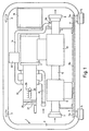
- Figure 1 shows schematically the essential parts of the metering device installed within the support frame 1.
- the support frame 1 consists essentially of two lateral, to a closed train in the form of a rectangle with rounded corners curved brackets 2 and two upper and lower webs 3, 4 connecting the brackets 2, the brackets 2 are substantially vertical, the webs 3, 4 horizontal and in the vicinity of the rounded Corners of the bracket 2 arranged.
- On the lower webs 4 feet 5 are provided for setting up the support frame.
- the upper webs 3 can be provided with handles for better transport.
- a line piece 6 with an inlet connection 7 and an outlet connection 8 is mounted on a plate 5b connected to it via vibration-damping elements 5a.
- the length of the line section 6 is selected so that the inlet connection 7 and the outlet connection 8 do not each protrude beyond the supporting frame.
- the inlet connection 7 and the outlet connection 8 are each designed as conventional water hose connections for connection to hydrants, fire engine tanks, etc.
- a filter 9 and a liquid counter 10 are also located in the line section 6.
- the liquid counter 10 is connected to the drive 11 of a metering pump 12 which, via an inlet 13, delivers metering agent from a metering agent supply (not shown) into a metering line 14, which runs between the liquid meter 10 and the drain port 8 opens into the line piece 6.
- a flow monitor 15 is installed in the metering line 14.
- the metering pump 12 and a control 16 schematically indicated in FIG. 1 are also arranged within the support frame 1 in such a way that they are surrounded or enclosed on all sides by the support frame 1. For vibration-proof storage, all parts enclosed by the support frame are mounted on the plate 5b.
- FIG. 2 shows schematically the structure and circuit of all parts of the metering device according to the invention.
- the line section 6 In the lower area of FIG. 2 is the line section 6 with the filter 9 and the liquid counter 10 shown.
- a valve 17 which can be controlled by the controller 16 is installed in the line piece 6 in terms of flow in front of the filter 9 and a check valve 18 is installed in terms of flow after the liquid counter 10.
- the middle part of FIG. 2 shows the metering pump 12 with the drive 11 and a metering part 19.
- the metering part 19 has a metering cylinder 20 in which a metering piston 21 can be displaced.
- the stroke movement of the metering piston 21 is limited on one side by an end face 22 of the metering cylinder 20 and on the other side by the end face 23 of a counter piston 24.
- the counter-piston 24 is arranged coaxially to the metering cylinder 20 and metering piston 21 and is displaceably mounted in the second end face 25 of the metering cylinder 20.
- the counter-piston 24 On the side of the counter-piston 24 facing away from the metering piston 21, the counter-piston 24 is connected via a spindle 26 to a handwheel 27, by the rotation of which the counter-piston 24 can be displaced axially relative to the metering cylinder 20.
- a handwheel 27 By the rotation of which the counter-piston 24 can be displaced axially relative to the metering cylinder 20.
- another manual or motor-operated adjustment of the counter-piston 24 is of course also possible.
- the position of the counter-piston 24 is displayed in the manner shown in FIG. 1 on a scale 29 via a pointer 28 connected to the counter-piston 24.
- the division of the scale 29 is preferably selected so that the position of the counter-piston 24 indicated by the pointer 28 on the scale 29 directly indicates the proportion of dosing agent in a manner described below.
- Two suction valves 30 and two pressure valves 31 are arranged on the peripheral surface of the metering cylinder 20 in the immediate vicinity of the two end faces 22, 25.
- the suction valves 30 connected via a connecting line 32 are connected to a dosing agent container 33 via an inlet 13 connected to the connecting line 32, in which the dosing agent 34 to be dosed is located.
- the pressure valves connected via a connecting line 35 are connected in the manner described above via a metering line 14 connected to the connecting line 35 to the line piece 6 at a metering point 36.
- a metering valve 37 and the flow monitor 15 are connected into the metering line 14, the output of which is connected to the controller 16 via the signal line 38.
- the metering line 14 also has a branch with a vent valve 39.
- the arrangement of the suction valves 30 and pressure valves 31 is selected so that inflow and outflow through the suction valve 30 or pressure valve 31 arranged on the end face 22 is possible until the metering piston 21 on the end face 22 which limits the stroke of the metering piston 21 on one side is present, or that the inflow and outflow through the suction valve 30 or pressure valve 31 arranged at the end face 25 is possible until the metering piston 21 abuts against the end face 23 of the counter-piston 24 which limits the stroke of the metering piston 21 on the other side, specifically regardless of the position of the counter-piston 24.
- the counter-piston 24 has a diameter which is smaller than that of the metering piston 21 or the inside diameter of the metering cylinder 20, so that there is a gap 40 between the metering piston 21 and metering cylinder 20 through the metering agent can flow into or from the displacement of the metering piston 21.
- the length of the counter-piston 24 is selected such that the stroke of the metering piston 21 becomes almost zero when the counter-piston 24 is pushed fully into the metering cylinder 20, ie the distance between the end face 22 and the end face 23 of the counter-piston 24 is approximately the height of the metering piston 21 corresponds.
- the counter-piston 24 can also be moved out of the metering cylinder 20 to such an extent that its end face 23 is approximately in one plane with the End face 25 of the metering cylinder is located. In this position, a maximum stroke of the metering piston 21 is possible.
- the metering piston 21 is connected to a drive piston 42 via a piston rod 41.
- the drive piston 42 is displaceable in a drive cylinder 43 adjoining the metering cylinder 20 on its end face 22.
- the length of the drive cylinder 43 corresponds to the length of the metering cylinder 20, so that in a position in which the metering piston 21 abuts the end face 22, the drive piston 42 abuts an end face 44 of the drive cylinder, and in a second position in which the metering piston 21 abuts the end face 23 of the counter-piston 24, when the latter is in its most advanced position, the drive cylinder 43 abuts the end face 45 of the drive cylinder 43 adjoining the end face 22.
- the drive cylinder 43 is connected to the line piece 6 via a line 46 or 47 opening into the drive cylinder 43 near the end face 44 or 45, a solenoid valve 48 or 49 and a line 50 opening into the line section 6.
- the inputs of the solenoid valves 48, 49 are each connected to corresponding outputs of the controller 16 via control lines 51, 52.
- the solenoid valves 48, 49 are switched so that one side of the drive piston 42 can be acted upon alternately via the line 50 with the pressure of the medium in the line section 6.
- a common drain line 53 is connected to the outlet side of the valves 48, 49 and opens into a container 54.
- the container 54 has an overflow 55 and an outlet 57 which can be closed by a valve 56.
- the outlet 57 is connected between the container 54 and the valve 56 via a line 58 to the metering line 14 via the vent valve 39.
- the piston rod 41 is formed such that it extends through the the end face 44 of the drive cylinder which is opposite the end face 45 adjoining the dosing cylinder 20 extends through it.
- a knob 59 is attached to the piston rod 41.
- the exposed part of the piston rod between drive cylinder 43 and knob 59 is covered by a bellows 60.
- the piston rod 41 therefore carries the knob 59 or the metering piston 21 at its two ends and the drive piston 42 in its central region and extends from the outside through both end faces 44, 45 of the drive cylinder 43 into the metering cylinder 20.
- the controller 16 has an input 62 connected to the liquid counter 10 via the signal line 61, an input 63 connected to the flow switch 15 via the signal line 38, and an input 65 connected to a battery 64 likewise arranged within the support frame. Another input 66 of the control 16 is connected via the signal line 67 to the output of a vacancy detector 68 arranged in the dosing agent container 33. On the controller 16 there are also terminals 69 for connecting a mains voltage of, for example, 220 V and terminals 70 for connecting a 12 V voltage supply. An output 71 is connected via a control line 72 to the valve 17, an output 73 via the control line 51 to the solenoid valve 48 and an output 74 via the control line 52 to the solenoid valve 49.
- Three optical signal devices are provided on the housing of the controller 16, namely an operating indicator 75 which lights up green when the metering device is in operation, a metering indicator 76 which lights up yellow via the signal line 38 when there is a signal from the flow monitor 15 and a signal which indicates the emptying of the metering agent container 33 from the vacancy indicator 68 via the signal line 67, red dosing agent level indicator 77.
- an operating indicator 75 which lights up green when the metering device is in operation
- a metering indicator 76 which lights up yellow via the signal line 38 when there is a signal from the flow monitor 15
- a signal which indicates the emptying of the metering agent container 33 from the vacancy indicator 68 via the signal line 67
- red dosing agent level indicator 77 On the control finally a main switch 78 is provided, in whose "0" position the metering setting is switched off, in whose "1" position the solenoid valves 48 and 49 are switched in unison and in whose "2" position the system
- the metering device In operation, the metering device according to the invention is moved to the place of use and set up there in a suitable manner.
- the inlet connection 7 is connected to a hydrant, the tank of a fire engine, a drinking water system or another existing pressurized water tank.
- a suitable spraying or spraying device is connected to the outlet connection 8.
- these can be connected to the corresponding terminals 69, 70 of the controller 16. If there is no connection to the terminals 69, 70, the controller 1 ' 6 is automatically supplied by the voltage source 64 built into the support frame 1.
- the dosing agent container 33 is also set up at the place of use and connected to the dosing pump 12 via the feed line 13.
- a suction lance 79 is preferably provided at the end of the feed line 13 and is introduced into the dosing agent container 33. Furthermore, the vacancy indicator 68 is inserted into the dosing agent container 33. In a particularly preferred embodiment, the vacancy indicator 68 is provided on the suction lance 79, so that only this has to be introduced into the dosing agent container 33. Finally, by actuating the handwheel 27, the counter-piston 24 is displaced until the pointer 28 on the scale 29 indicates the desired or required concentration of the dosing agent.
- the control 16 By switching the main switch 78 to its "2" position, the control 16 opens the valve 17 via the signal line 72 and liquid begins through the line section 6 with filter 9, liquid counter 10 and check valve 18 to flow to the spraying or spraying device.
- the liquid counter 10 supplies, depending on the amount of liquid flowing through per time, signals via the signal line 61 to the controller 16.
- This shows the operating state by the green operating indicator 75 lighting up and switches the solenoid valves 48, 49 via the control lines 51, 52 so that the Drive piston 42 is acted upon from both sides alternately with pressure of the liquid via line 50.
- the drive piston 42 executes a reciprocating movement.
- the number of strokes of the drive piston 42 per time is determined by the switching cycle of the valves 48, 49 specified by the controller 16.
- This cycle is determined by the controller 16 on the basis of the signals from the liquid counter 10.
- the size of the stroke of the drive piston 42 and thus the metering piston 21 carried out after each switchover is determined by the preselected position of the counter-piston 24.
- the dosing piston With each stroke movement, the dosing piston sucks dosing agent from the dosing agent container 33 on one side via the suction valves 30 and the inlet line 13 and, on the other hand, conveys dosing agent sucked in during the previous movement via the pressure valves 31 and the dosing line 14 to the dosing point 36 into the liquid flow .
- the metering piston moves between the end face 22 of the metering cylinder and the end face 23 of the counter-piston.
- the setting of the dosing agent concentration in the liquid flow is thus carried out on the one hand by the number of strokes of the dosing piston 21 per time, and on the other hand by the stroke of the dosing piston 21 limited by the counter-piston 24 Given the dosing agent flow, the dosing agent concentration can be clearly adjusted by moving the counter-piston 24.
- the flow monitor 15 detects a metering agent flow, which is indicated by the yellow metering display 76. Dosing Lack of tele is reported by the vacancy detector 68 to the control 16 via the signal line 67 and causes the dosing agent empty indicator 77 to light up.
- the amount of liquid used to actuate the drive piston 42 runs through the drain line 53 into the container 54 and collects there up to the level of the overflow 55.
- the inlet connection 7 and the outlet connection 8 are separated, the main switch into the "1" position (Synchronization of the solenoid valves 48, 49) moved and the suction lance 79 inserted into the container 54.
- the dosing pump is now rinsed by hand. This is done in such a way that the metering piston 21 is moved back and forth by hand by means of the knob 59. With each stroke movement, the metering piston 21 sucks liquid out of the container 54 and presses it into the metering line 14.
- the metering pump can then be dewatered in that the suction opening of the suction lance 79 is kept outside, the vent valve 39 is opened and the metering pump is actuated by means of the knob 59 by moving it back and forth.
- a mobile metering device which can be brought to almost any vehicle to its place of use, can be easily set up there and is independent of the energy supply available there. This is achieved in particular in that the energy required to drive the metering pump is taken from the pressure of the liquid. Therefore, only energy is required to control the metering pump and the display devices. Furthermore, the volumetric dosing enables high dosing accuracy regardless of the dosing back pressure, the pressure of the liquid in line piece 6. The dosing pump also works regardless of the viscosity of the dosing medium due to this chemical composition or environmental conditions. After use, the dosing device can be rinsed and vented by hand.
- the metering device according to the invention is therefore particularly suitable for detoxification or decontamination in the civil protection area, in the military area and in the fire service area when metering agents are added to a water stream.
Landscapes
- General Physics & Mathematics (AREA)
- Physics & Mathematics (AREA)
- Engineering & Computer Science (AREA)
- Chemical & Material Sciences (AREA)
- Fluid Mechanics (AREA)
- Organic Chemistry (AREA)
- Environmental & Geological Engineering (AREA)
- Water Supply & Treatment (AREA)
- Health & Medical Sciences (AREA)
- Hydrology & Water Resources (AREA)
- Life Sciences & Earth Sciences (AREA)
- Medicinal Chemistry (AREA)
- Automation & Control Theory (AREA)
- Feeding, Discharge, Calcimining, Fusing, And Gas-Generation Devices (AREA)
- Electrical Discharge Machining, Electrochemical Machining, And Combined Machining (AREA)
- Auxiliary Devices For Machine Tools (AREA)
- Cyclones (AREA)
- Loading And Unloading Of Fuel Tanks Or Ships (AREA)
Applications Claiming Priority (2)
| Application Number | Priority Date | Filing Date | Title |
|---|---|---|---|
| DE19823236488 DE3236488A1 (de) | 1982-10-01 | 1982-10-01 | Dosiereinrichtung |
| DE3236488 | 1982-10-01 |
Publications (2)
| Publication Number | Publication Date |
|---|---|
| EP0108740A2 true EP0108740A2 (fr) | 1984-05-16 |
| EP0108740A3 EP0108740A3 (fr) | 1984-11-28 |
Family
ID=6174736
Family Applications (1)
| Application Number | Title | Priority Date | Filing Date |
|---|---|---|---|
| EP83890156A Withdrawn EP0108740A3 (fr) | 1982-10-01 | 1983-09-09 | Dispositif de dosage |
Country Status (5)
| Country | Link |
|---|---|
| US (1) | US4554939A (fr) |
| EP (1) | EP0108740A3 (fr) |
| JP (1) | JPS5979812A (fr) |
| CA (1) | CA1200700A (fr) |
| DE (1) | DE3236488A1 (fr) |
Cited By (3)
| Publication number | Priority date | Publication date | Assignee | Title |
|---|---|---|---|---|
| EP0181434A1 (fr) * | 1984-10-23 | 1986-05-21 | Deutsche Babcock Werke Aktiengesellschaft | Dispositif et procédé pour attribuer des quantités petites et très petites de liquide à un utilisateur |
| EP0551761A1 (fr) * | 1992-01-16 | 1993-07-21 | Imperial Chemical Industries Plc | Dispositif pour le traitement des eaux usées |
| EP1549401A4 (fr) * | 2002-08-02 | 2007-08-08 | Pierce Mfg Inc | Systeme de proportionnage de concentre de mousse et procedes destines a des vehicules de sauvetage et de lutte contre les incendies |
Families Citing this family (20)
| Publication number | Priority date | Publication date | Assignee | Title |
|---|---|---|---|---|
| DE3430130A1 (de) * | 1984-08-16 | 1986-02-27 | Edmund Bühler GmbH & Co, 7400 Tübingen | Vorrichtung zur entnahme von fluessigkeitsproben |
| DE3437173A1 (de) * | 1984-10-10 | 1986-04-10 | Digmesa AG Digitale Messtechnik, Biel | Verfahren und vorrichtung zum dosierten zugeben einer zusatzfluessigkeit zu einer hauptfluessigkeit |
| US5234268A (en) * | 1987-12-23 | 1993-08-10 | Chemstation International, Inc. | Cleaning solution mixing and metering process |
| US5020917A (en) * | 1987-12-23 | 1991-06-04 | Chemstation International, Inc. | Cleaning solution mixing and metering system |
| GB8806352D0 (en) * | 1988-03-17 | 1988-04-13 | British Res Agricult Eng | Preparing mixed liquids |
| US5174383A (en) * | 1988-09-08 | 1992-12-29 | Hypro Corporation | Apparatus and method for controlling the introduction of chemical foamant into water stream in fire-fighting equipment |
| US5143257A (en) * | 1990-12-04 | 1992-09-01 | Kelrus Corp. | System for proportioned liquid dispensing |
| US5381926A (en) * | 1992-06-05 | 1995-01-17 | The Coca-Cola Company | Beverage dispensing value and method |
| US5611937A (en) * | 1995-05-12 | 1997-03-18 | The Coca-Cola Company | Water Treating apparatus and method |
| US6725940B1 (en) | 2000-05-10 | 2004-04-27 | Pierce Manufacturing Inc. | Foam additive supply system for rescue and fire fighting vehicles |
| US20060243324A1 (en) * | 2005-04-29 | 2006-11-02 | Pierce Manufacturing Inc. | Automatic start additive injection system for fire-fighting vehicles |
| FR2895920B1 (fr) * | 2006-01-06 | 2008-04-18 | Gilson Sas Soc Par Actions Sim | Pipette multivolumes. |
| US8257594B2 (en) * | 2008-02-07 | 2012-09-04 | 3M Innovative Properties Company | Twin tank water-on-water filtration system |
| FR2927999B1 (fr) * | 2008-02-21 | 2010-09-17 | Gilson Sas | Viscosimetre comprenant un systeme de pipetage, a precision amelioree et conception simplifiee |
| US8183810B2 (en) | 2009-09-08 | 2012-05-22 | Hoffman Enclosures, Inc. | Method of operating a motor |
| US8297369B2 (en) | 2009-09-08 | 2012-10-30 | Sta-Rite Industries, Llc | Fire-extinguishing system with servo motor-driven foam pump |
| US8164293B2 (en) | 2009-09-08 | 2012-04-24 | Hoffman Enclosures, Inc. | Method of controlling a motor |
| US10125002B2 (en) * | 2014-07-13 | 2018-11-13 | Sestra Systems, Inc | Beverage dispensing system |
| DE102021115218A1 (de) * | 2021-06-11 | 2022-12-15 | Otto ID Solutions GmbH | Entleerungserkennungsvorrichtung, Entleerungssystem und Entleerungserkennungsverfahren |
| CN118791112B (zh) * | 2024-09-12 | 2024-12-10 | 中国航空工业集团公司济南特种结构研究所 | 一种含氰废水处理装置 |
Family Cites Families (14)
| Publication number | Priority date | Publication date | Assignee | Title |
|---|---|---|---|---|
| US1740683A (en) * | 1920-07-12 | 1929-12-24 | Sullivan Machinery Co | Feeding apparatus |
| US2527136A (en) * | 1946-08-16 | 1950-10-24 | Western Electric Co | Fluid mixing apparatus |
| US2837105A (en) * | 1955-09-30 | 1958-06-03 | Badger Meter Mfg Co | Proportioning feeder |
| DE1244428B (de) * | 1960-04-26 | 1967-07-13 | Minimax Ag | Vorrichtung zum Zumischen einer Zumischfluessigkeit zu einem Hauptfluessigkeitsstromin einem festen Mischungsverhaeltnis |
| US3506025A (en) * | 1965-03-30 | 1970-04-14 | Elastizell Corp Of America | Proportional blending apparatus |
| CH561902A5 (en) * | 1973-12-17 | 1975-05-15 | Bolla Ernesto Lino | Additive injection into rinsing and washing plant lines - double piston injection valve uses existing feed water pressure |
| US4119113A (en) * | 1975-02-06 | 1978-10-10 | Extracorporeal Medical Systems, Inc. | Double-action proportioning pump |
| US4073304A (en) * | 1976-07-12 | 1978-02-14 | Suntech, Inc. | System for calibrating a pump |
| US4189067A (en) * | 1977-02-14 | 1980-02-19 | Lykes Pasco Packing Company, Dispenser Division | Electronic control for dispenser system |
| DE3100708A1 (de) * | 1980-01-31 | 1981-12-17 | Arcana Chem.-pharm. Fabrik GmbH, 9802 Spittal, Drau | Dosiervorrichtung |
| US4341237A (en) * | 1980-03-17 | 1982-07-27 | Valmont Industries, Inc. | Apparatus and method for reducing the waste of welding gas |
| US4337786A (en) * | 1980-06-23 | 1982-07-06 | Valmont Industries, Inc. | Variable rate fertilizer injection system |
| US4391291A (en) * | 1981-02-24 | 1983-07-05 | Hume Ronald W | Apparatus for reconstituting a concentrate |
| US4392508A (en) * | 1981-04-15 | 1983-07-12 | Ryco Graphic Manufacturing, Inc. | Proportional mixing system with water motor drive |
-
1982
- 1982-10-01 DE DE19823236488 patent/DE3236488A1/de not_active Withdrawn
-
1983
- 1983-09-09 EP EP83890156A patent/EP0108740A3/fr not_active Withdrawn
- 1983-09-20 US US06/533,934 patent/US4554939A/en not_active Expired - Fee Related
- 1983-09-22 JP JP58174451A patent/JPS5979812A/ja active Pending
- 1983-09-30 CA CA000438052A patent/CA1200700A/fr not_active Expired
Cited By (3)
| Publication number | Priority date | Publication date | Assignee | Title |
|---|---|---|---|---|
| EP0181434A1 (fr) * | 1984-10-23 | 1986-05-21 | Deutsche Babcock Werke Aktiengesellschaft | Dispositif et procédé pour attribuer des quantités petites et très petites de liquide à un utilisateur |
| EP0551761A1 (fr) * | 1992-01-16 | 1993-07-21 | Imperial Chemical Industries Plc | Dispositif pour le traitement des eaux usées |
| EP1549401A4 (fr) * | 2002-08-02 | 2007-08-08 | Pierce Mfg Inc | Systeme de proportionnage de concentre de mousse et procedes destines a des vehicules de sauvetage et de lutte contre les incendies |
Also Published As
| Publication number | Publication date |
|---|---|
| EP0108740A3 (fr) | 1984-11-28 |
| CA1200700A (fr) | 1986-02-18 |
| US4554939A (en) | 1985-11-26 |
| JPS5979812A (ja) | 1984-05-09 |
| DE3236488A1 (de) | 1984-04-05 |
Similar Documents
| Publication | Publication Date | Title |
|---|---|---|
| EP0108740A2 (fr) | Dispositif de dosage | |
| DE3730220C1 (de) | Verfahren zur Aufbereitung des Wassers eines Schwimmbades | |
| DE2122133C3 (de) | Prüfeinrichtung an schwimmergesteuerten Flüssigkeitsanzeigen | |
| EP0544274A2 (fr) | Dispositif de traitement médical, en particulier à des fins chirurgicales avec conduit d'alimentation en forme de tube flexible | |
| EP0098419B1 (fr) | Installation de dosage de désinfectant dans l'eau | |
| DE3015215A1 (de) | Vorrichtung zur dosierten abgabe eines komprimierten gasfoermigen mediums | |
| DE19717009A1 (de) | Verfahren zum Befüllen eines Trinkwassertanks und Vorrichtung zur Trinkwasserversorgung | |
| DE7611930U1 (de) | Vorrichtung zum mischen von koernigem oder pulverfoermigem material mit einem oder mehreren zusatzstoffen | |
| DD141357A5 (de) | Vorrichtung zur erzielung einer lagenverseilung auf doppelschlagmaschinen | |
| DE60108700T2 (de) | Entleer- und Befüllvorrichtung für Kühlsysteme | |
| DE2744776B2 (de) | Vorrichtung zum Wechseln von Schmieröl in Maschinen | |
| DE1553022A1 (de) | Vorrichtung zum Saugen von Fluessigkeit,Luft und festen Teilchen | |
| DE211997C (fr) | ||
| EP0160815A2 (fr) | Appareil pour mesurer le contenu en huile d'une eau | |
| DE3122519C2 (fr) | ||
| EP1099487B1 (fr) | Procédé, dispositif et additif détergent pour le nettoyage chimique de conduites | |
| DE202025105256U1 (de) | System zum Herstellen und Leiten eines Gemisches aus mindestens zwei Substanzen | |
| DE8620048U1 (de) | Naßbehandlungsgerät für fotografisches Material | |
| DE10114255A1 (de) | Aggregateeinheit für Kleinkläranlagen | |
| DE8907912U1 (de) | Vorrichtung zum Entsorgen und Versorgen von Grubenbetrieben und Tagesbetrieben von bzw. mit umweltschädlichen Flüssigkeiten | |
| DE3330812C1 (de) | Güllepumpstation | |
| AT386086B (de) | Vorrichtung zum einleiten einer hochkonzentrierten loesung eines in einem behaelter enthaltenen desinfektionsmittels in die wasserzuleitung zu einer zapfstelle | |
| DE493166C (de) | Fluessigkeitsmess- und Zapfvorrichtung, insbesondere fuer gaerungsfaehige Fluessigkeiten, wie Milch | |
| DE20011779U1 (de) | Vorrichtung zum Mischen von Flüssigkeiten | |
| DE3921090A1 (de) | Landwirtschaftliche feldspritze |
Legal Events
| Date | Code | Title | Description |
|---|---|---|---|
| PUAI | Public reference made under article 153(3) epc to a published international application that has entered the european phase |
Free format text: ORIGINAL CODE: 0009012 |
|
| AK | Designated contracting states |
Designated state(s): AT BE CH DE FR GB IT LI LU NL SE |
|
| PUAL | Search report despatched |
Free format text: ORIGINAL CODE: 0009013 |
|
| AK | Designated contracting states |
Designated state(s): AT BE CH DE FR GB IT LI LU NL SE |
|
| 17P | Request for examination filed |
Effective date: 19841102 |
|
| STAA | Information on the status of an ep patent application or granted ep patent |
Free format text: STATUS: THE APPLICATION IS DEEMED TO BE WITHDRAWN |
|
| 18D | Application deemed to be withdrawn |
Effective date: 19860724 |
|
| RIN1 | Information on inventor provided before grant (corrected) |
Inventor name: HASLBERGER, RICHARD Inventor name: KERN, HANS |