EP0108741A1 - Procédé de fabrication d'un corps d'éclats - Google Patents
Procédé de fabrication d'un corps d'éclats Download PDFInfo
- Publication number
- EP0108741A1 EP0108741A1 EP19830890176 EP83890176A EP0108741A1 EP 0108741 A1 EP0108741 A1 EP 0108741A1 EP 19830890176 EP19830890176 EP 19830890176 EP 83890176 A EP83890176 A EP 83890176A EP 0108741 A1 EP0108741 A1 EP 0108741A1
- Authority
- EP
- European Patent Office
- Prior art keywords
- inner body
- splinters
- hollow body
- splinter
- filled
- Prior art date
- Legal status (The legal status is an assumption and is not a legal conclusion. Google has not performed a legal analysis and makes no representation as to the accuracy of the status listed.)
- Granted
Links
- 238000000034 method Methods 0.000 title claims description 16
- 238000004519 manufacturing process Methods 0.000 title abstract description 6
- 238000013467 fragmentation Methods 0.000 title abstract 2
- 238000006062 fragmentation reaction Methods 0.000 title abstract 2
- 206010041662 Splinter Diseases 0.000 claims description 62
- 239000012634 fragment Substances 0.000 claims description 15
- 230000006835 compression Effects 0.000 claims description 2
- 238000007906 compression Methods 0.000 claims description 2
- 238000005476 soldering Methods 0.000 claims description 2
- 238000003466 welding Methods 0.000 claims description 2
- 239000000463 material Substances 0.000 description 6
- 238000004880 explosion Methods 0.000 description 2
- 239000002360 explosive Substances 0.000 description 2
- 238000005242 forging Methods 0.000 description 2
- 230000005484 gravity Effects 0.000 description 2
- 230000000087 stabilizing effect Effects 0.000 description 2
- 229910000831 Steel Inorganic materials 0.000 description 1
- 230000002411 adverse Effects 0.000 description 1
- 229910052782 aluminium Inorganic materials 0.000 description 1
- XAGFODPZIPBFFR-UHFFFAOYSA-N aluminium Chemical compound [Al] XAGFODPZIPBFFR-UHFFFAOYSA-N 0.000 description 1
- 230000009172 bursting Effects 0.000 description 1
- 239000000919 ceramic Substances 0.000 description 1
- 238000005474 detonation Methods 0.000 description 1
- 239000012530 fluid Substances 0.000 description 1
- 239000007789 gas Substances 0.000 description 1
- 229910052751 metal Inorganic materials 0.000 description 1
- 239000002184 metal Substances 0.000 description 1
- 239000000203 mixture Substances 0.000 description 1
- 239000007779 soft material Substances 0.000 description 1
- 239000010959 steel Substances 0.000 description 1
Images

Classifications
-
- F—MECHANICAL ENGINEERING; LIGHTING; HEATING; WEAPONS; BLASTING
- F42—AMMUNITION; BLASTING
- F42B—EXPLOSIVE CHARGES, e.g. FOR BLASTING, FIREWORKS, AMMUNITION
- F42B12/00—Projectiles, missiles or mines characterised by the warhead, the intended effect, or the material
- F42B12/02—Projectiles, missiles or mines characterised by the warhead, the intended effect, or the material characterised by the warhead or the intended effect
- F42B12/20—Projectiles, missiles or mines characterised by the warhead, the intended effect, or the material characterised by the warhead or the intended effect of high-explosive type
- F42B12/22—Projectiles, missiles or mines characterised by the warhead, the intended effect, or the material characterised by the warhead or the intended effect of high-explosive type with fragmentation-hull construction
- F42B12/32—Projectiles, missiles or mines characterised by the warhead, the intended effect, or the material characterised by the warhead or the intended effect of high-explosive type with fragmentation-hull construction the hull or case comprising a plurality of discrete bodies, e.g. steel balls, embedded therein or disposed around the explosive charge
Definitions
- the present invention relates to a splinter body and to a method for producing a splinter body.
- a splinter body for splinter projectiles and warheads which has a projectile jacket, which serves as an outer shell, and an inner tube body.
- the cylindrical cavity formed between these two bodies is covered with splinters e.g. made of hard metal or ceramic.
- splinters can have a spherical shape, but also have different shapes, each being a uniform mixture, e.g. Spheres with pyramids.
- the fragments are removed by pressurizing the inner body, the inner sleeve, e.g. by explosion forming, electromagnetically or by driving a conical calibration bolt or the like, pressed outwards, the splinters being enclosed on both sides in both tubular bodies.
- This method also has the advantage that a plurality of layers of fragments are provided, in which case a further inner shell is then provided for each splinter layer and the fragments are fully embedded in the material of the shells after the inner body (s) have been pressurized.
- a further method for producing a splinter body is known, a base being screwed into a cylindrical shell body, after which a cylinder sleeve is inserted into the interior. The cavity between the shell and the inner sleeve is then filled with the fragments. The distance between the inner wall of the shell and the outer wall of the inner sleeve corresponds approximately to that of the spherical splinters.
- the splinters are now fixed in such a way that, for example, the interior is pressurized with a hydraulic fluid, so that they are made of a soft material, e.g. Aluminum, existing inner sleeve is deformed so that the splinters are partially enveloped.
- splinter bodies and the associated processes all have in common that they are only suitable for producing splinter bodies which provide an essentially cylindrical arrangement of the splinters, i.e. there is no possibility of arranging the splinters in a tapering area and the methods are relatively complex, in particular if the splinters are to be covered on all sides by the jacket material of the inner sleeve, the splinters can break and then these sections no longer have the desired kinetic energy when the splinter body explodes.
- the object of the present invention is to provide an easy-to-carry out process for the production of such splinter bodies with one or more layers To create a series of splinters, whereby all-round covering of the splinters is not required for the safe positioning of the same on the floor. This safe positioning of the fragments in the floor is of particular importance for the ballistic properties.
- Another object of the invention is that simply shaped bodies, in particular pipe sections, can be used as starting products for carrying out the method.
- the method according to the invention for producing a splinter body wherein a preformed inner body is introduced into a hollow body, in particular the shell, and at least partially the space thus formed is filled with the desired amount of splinters and the inner body is expanded in the radial direction and the adjacent body
- Surrounding splinters at least partially consists essentially in that the inner body, which is tapered at least at one end, in particular at both ends, is introduced into the hollow body, whereupon the latter is deformed in accordance with the desired space and the space is filled with the fragments, after which the inner body is radial Direction, especially with a pressure medium, possibly with simultaneous axial compression, is expanded.
- the center of gravity of the projectile can be determined in a particularly simple manner by choosing the splinters. If balls are used as splinters, the diameter of which is equal to the distance between the hollow body and the inner body, these balls will have a lower bulk density than if smaller balls were used. There is also the possibility that, for example, other shapes can be used instead of the balls, in which case other densest bulk densities are also given.
- the intermediate space can be filled with splinters in multiple layers in relation to the radial direction, the splinters not being destroyed even when there is no intermediate sleeve.
- a particularly preferred embodiment of the present invention consists in that the inner body is formed from a cylindrical tube by drawing in the ends.
- the inner body has the surprising property that, despite different deformations, in particular cold deformation when pressurized and bursting, it has homogeneous properties.
- the inner body tapered at least at one end is introduced into a tube forming the hollow body and into the Sem positioned, whereupon the tube is at least at one, preferably at both ends, is a particularly easy to perform method, it can be assumed at the same time from pipe sections and it was quite surprising that pipe sections that are subject to different cold deformation, with explosive Pressurization has no adverse behavior, such as the size of the splinters, etc.
- the splinter body according to the invention with an inner body and a hollow body, in particular forming the projectile jacket, the space formed between them being at least partially filled with splinters consists essentially in that the inner body tapers at least at one end, and with the hollow body by soldering, welding or the like. is connected.
- Such a splinter body can not only have a cylindrical layer of splinters, but can also have such splinters in the tapered part.
- those parts which are usually provided for screw connections or the like can be replaced by weight by further splitters. It has been shown completely surprisingly that neither the weld seam nor the heat exposure caused by it affects the behavior after the detonation of the explosive charge and thus the desired comminution of the projectile.
- the inner body has an internal thread at one end, it is particularly easy to mount stabilizing fins or the igniter. Furthermore, the different material thickness of the inner and outer body is taken into account particularly favorably, since, as is known per se, the inner body should have a greater material thickness than the outer body, since the inner body is only allowed to burst in the event of an explosion after the greatest possible pressure has been built up, so that the under pressure gases cause the splinters to act at high speed.
- the outer body should have the smallest possible wall thickness so that the energy of the splinters is not used to destroy the outer shell, but rather that the splinters can leave their position with the highest possible energy.
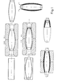
- Fig. 1 shows a schematic representation of the individual steps, whereas in Fig. 2 the section through a splinter body is shown.
- a cylindrical tube is formed into a desired inner body by necking with a shape at both ends, and then an internal thread is cut at both ends.
- This inner body is then introduced into a tube with a larger diameter, which is to form the outer hollow body, and is positioned therein, for example by a mold.
- the outer tube is then also held in a mold, with this being deformed at one end until it lies against the inner body, whereas the deformation at the other end is only carried out until an annular gap is released.
- the fragments are now introduced through this annular gap.
- the inner body is then closed pressure-tight at both ends with movable stamps.
- a pressure medium for example with a pressure of 700 bar, is now introduced into the interior of the inner body, the two ends of the inner body being pressed against one another at the same time, so that in addition to the radial expansion, the inner body is shortened.
- the outer body is also arranged in a shape so that it acts against deformation of the outer body and can absorb the forces. Then the annular filling opening closed by necking the outer hollow body, whereupon the inner body is connected to the hollow body by circular welds.
- the splinter body shown in FIG. 2 has an inner body 1 which projects at both ends 2 and 3 beyond the outer hollow body 4.
- the outer hollow body 4 is also necked in at its two ends 5, 6 and lies against the ends 2, 3 of the inner body and is connected to them by welds 7, 8.
- the intermediate space 9, which is formed by the spaced-apart inner body and outer hollow body formed from tubes, is filled with splinters 10, 11, 12. If, for example, the cylindrical area of the intermediate space is only filled with large balls 11 as fragments, then by filling the tapering areas at one or the other end with smaller size splinters, the center of gravity of the entire projectile can be shifted in one of these two directions.
- a different bulk density of the splinters can, however, not only be achieved by the different sizes, but also by different shapes and also by using different materials. However, it is essential that the filling of the different fragments takes place in such a way that a rotationally symmetrical structure of the splinter body can be achieved in each case.
- the inner body 1 has threads 13, 14 at its two ends which can be used for fastening, for example an igniter and stabilizing fins.
- the inner body can have a wall thickness of 5 mm, the thickness of the outer jacket being 2 mm.
- steels with a tensile strength of at least 7 00 N / mm 2 are suitable as the material for the inner and outer sheath.
Landscapes
- Engineering & Computer Science (AREA)
- Chemical & Material Sciences (AREA)
- Combustion & Propulsion (AREA)
- General Engineering & Computer Science (AREA)
- Shaping Metal By Deep-Drawing, Or The Like (AREA)
- Aiming, Guidance, Guns With A Light Source, Armor, Camouflage, And Targets (AREA)
Applications Claiming Priority (2)
| Application Number | Priority Date | Filing Date | Title |
|---|---|---|---|
| AT375582A AT382236B (de) | 1982-10-11 | 1982-10-11 | Verfahren zur herstellung eines splitterkoerpers und danach hergestellter splitterkoerper |
| AT3755/82 | 1982-10-11 |
Publications (2)
| Publication Number | Publication Date |
|---|---|
| EP0108741A1 true EP0108741A1 (fr) | 1984-05-16 |
| EP0108741B1 EP0108741B1 (fr) | 1987-04-08 |
Family
ID=3554970
Family Applications (1)
| Application Number | Title | Priority Date | Filing Date |
|---|---|---|---|
| EP19830890176 Expired EP0108741B1 (fr) | 1982-10-11 | 1983-10-10 | Procédé de fabrication d'un corps d'éclats |
Country Status (4)
| Country | Link |
|---|---|
| EP (1) | EP0108741B1 (fr) |
| AT (1) | AT382236B (fr) |
| DE (1) | DE3370859D1 (fr) |
| GR (1) | GR78674B (fr) |
Cited By (8)
| Publication number | Priority date | Publication date | Assignee | Title |
|---|---|---|---|---|
| GB2179125A (en) * | 1985-07-13 | 1987-02-25 | Diehl Gmbh & Co | Warhead |
| DE3822375A1 (de) * | 1987-09-28 | 1989-04-20 | Affarsverket Ffv | Detonationskoerper |
| EP0253058B1 (fr) * | 1986-07-15 | 1990-06-27 | Rheinmetall GmbH | Projectile à calibre réduit |
| US5979332A (en) * | 1997-04-23 | 1999-11-09 | Diehl Stiftung & Co. | Fragmentation body for a fragmentation projectile |
| WO2002003017A1 (fr) * | 2000-07-03 | 2002-01-10 | Bofors Defence Ab | Cone de charge modulaire pour munitions, pour missiles notamment |
| WO2002003015A1 (fr) * | 2000-07-03 | 2002-01-10 | Bofors Defence Ab | Dispositif d'adaptation d'une unite de munition pour differents types de cibles et de situations |
| SE2100078A1 (sv) * | 2021-05-19 | 2022-11-20 | Bae Systems Bofors Ab | Stridsdel |
| RU2794586C1 (ru) * | 2022-11-11 | 2023-04-21 | Российская Федерация, от имени которой выступает Государственная корпорация по атомной энергии "Росатом" (Госкорпорация "Росатом") | Способ изготовления корпуса осколочно-фугасного заряда |
Families Citing this family (1)
| Publication number | Priority date | Publication date | Assignee | Title |
|---|---|---|---|---|
| RU2160881C2 (ru) * | 1989-06-29 | 2000-12-20 | Государственное унитарное предприятие "Государственное научно-производственное предприятие "Сплав" | Боеприпас осколочного действия |
Citations (4)
| Publication number | Priority date | Publication date | Assignee | Title |
|---|---|---|---|---|
| CH543064A (de) * | 1971-07-08 | 1973-10-15 | Oerlikon Buehrle Ag | Geschoss mit kugelförmigen, unter sich gleich grossen Projektilen, Verfahren zu dessen Herstellung und Vorrichtung zur Durchführung des Verfahrens |
| DE2129196B2 (fr) * | 1971-06-12 | 1975-04-03 | Fa. Diehl, 8500 Nuernberg | |
| EP0012322A1 (fr) * | 1978-12-06 | 1980-06-25 | DIEHL GMBH & CO. | Procédé pour fabriquer des produits métalliques, notamment des projectiles, en incorporant des particules distinctes dans une masse d'enrobage métallique |
| EP0012323A1 (fr) * | 1978-12-06 | 1980-06-25 | DIEHL GMBH & CO. | Procédé pour fabriquer des produits métalliques, notamment des projectiles, en incorporant des particules distinctes dans une masse d'enrobage métallique |
-
1982
- 1982-10-11 AT AT375582A patent/AT382236B/de not_active IP Right Cessation
-
1983
- 1983-08-23 GR GR72275A patent/GR78674B/el unknown
- 1983-10-10 DE DE8383890176T patent/DE3370859D1/de not_active Expired
- 1983-10-10 EP EP19830890176 patent/EP0108741B1/fr not_active Expired
Patent Citations (4)
| Publication number | Priority date | Publication date | Assignee | Title |
|---|---|---|---|---|
| DE2129196B2 (fr) * | 1971-06-12 | 1975-04-03 | Fa. Diehl, 8500 Nuernberg | |
| CH543064A (de) * | 1971-07-08 | 1973-10-15 | Oerlikon Buehrle Ag | Geschoss mit kugelförmigen, unter sich gleich grossen Projektilen, Verfahren zu dessen Herstellung und Vorrichtung zur Durchführung des Verfahrens |
| EP0012322A1 (fr) * | 1978-12-06 | 1980-06-25 | DIEHL GMBH & CO. | Procédé pour fabriquer des produits métalliques, notamment des projectiles, en incorporant des particules distinctes dans une masse d'enrobage métallique |
| EP0012323A1 (fr) * | 1978-12-06 | 1980-06-25 | DIEHL GMBH & CO. | Procédé pour fabriquer des produits métalliques, notamment des projectiles, en incorporant des particules distinctes dans une masse d'enrobage métallique |
Cited By (16)
| Publication number | Priority date | Publication date | Assignee | Title |
|---|---|---|---|---|
| GB2179125A (en) * | 1985-07-13 | 1987-02-25 | Diehl Gmbh & Co | Warhead |
| GB2179125B (en) * | 1985-07-13 | 1989-07-19 | Diehl Gmbh & Co | Warhead |
| EP0253058B1 (fr) * | 1986-07-15 | 1990-06-27 | Rheinmetall GmbH | Projectile à calibre réduit |
| DE3822375A1 (de) * | 1987-09-28 | 1989-04-20 | Affarsverket Ffv | Detonationskoerper |
| US5979332A (en) * | 1997-04-23 | 1999-11-09 | Diehl Stiftung & Co. | Fragmentation body for a fragmentation projectile |
| SG82583A1 (en) * | 1997-04-23 | 2001-08-21 | Diehl Stiftung & Co | Fragmentation body for a fragmentation projectile |
| US7066093B2 (en) | 2000-07-03 | 2006-06-27 | Bae Systems Bofors Ab | Modular warhead for units of ammunition such as missiles |
| WO2002003015A1 (fr) * | 2000-07-03 | 2002-01-10 | Bofors Defence Ab | Dispositif d'adaptation d'une unite de munition pour differents types de cibles et de situations |
| WO2002003017A1 (fr) * | 2000-07-03 | 2002-01-10 | Bofors Defence Ab | Cone de charge modulaire pour munitions, pour missiles notamment |
| US7127995B2 (en) | 2000-07-03 | 2006-10-31 | Bae Systems Bofors Ab | Device for adapting a unit of ammunition for different types of targets and situations |
| SE2100078A1 (sv) * | 2021-05-19 | 2022-11-20 | Bae Systems Bofors Ab | Stridsdel |
| WO2022245264A1 (fr) * | 2021-05-19 | 2022-11-24 | Bae Systems Bofors Ab | Procédé de fabrication d'un composant de tête explosive |
| SE545386C2 (sv) * | 2021-05-19 | 2023-07-25 | Bae Systems Bofors Ab | Metod för framställning av en komponent för en stridsdel |
| US12276486B2 (en) | 2021-05-19 | 2025-04-15 | Bae Systems Bofors Ab | Method for producing a warhead component |
| RU2794586C1 (ru) * | 2022-11-11 | 2023-04-21 | Российская Федерация, от имени которой выступает Государственная корпорация по атомной энергии "Росатом" (Госкорпорация "Росатом") | Способ изготовления корпуса осколочно-фугасного заряда |
| RU2837186C1 (ru) * | 2024-02-28 | 2025-03-26 | Акционерное общество "Научно-производственное объединение "Прибор" имени С.С. Голембиовского" | Способ изготовления боевой части осколочно-фугасной авиабомбы |
Also Published As
| Publication number | Publication date |
|---|---|
| EP0108741B1 (fr) | 1987-04-08 |
| GR78674B (fr) | 1984-09-27 |
| DE3370859D1 (en) | 1987-05-14 |
| AT382236B (de) | 1987-01-26 |
| ATA375582A (de) | 1986-06-15 |
Similar Documents
| Publication | Publication Date | Title |
|---|---|---|
| DE2129196C3 (de) | Splitterkörper für Splittergeschosse und -gefechtskopfe | |
| DE4001864C2 (fr) | ||
| DE112010003307B4 (de) | Trennvorrichtung mit expandierender Röhre | |
| EP0344224B1 (fr) | Manchon a fractionnement pour corps explosif metallique et procede de fabrication | |
| DE2253440A1 (de) | Patronenhuelse aus einem thermoplastischen material | |
| CH618260A5 (fr) | ||
| EP2101935A1 (fr) | Pièce et procédé pour le formage par explosion | |
| DE60021398T2 (de) | Zünder | |
| EP0108741B1 (fr) | Procédé de fabrication d'un corps d'éclats | |
| AT350516B (de) | Verfahren zur herstellung eines schutzmantels fuer die fuellung eines druckgasbehaelters | |
| DE2557676A1 (de) | Splittergeschoss | |
| DD150860A5 (de) | Verfahren zum explosionsschweissen | |
| DE2408801A1 (de) | Verfahren zum festen und vorzugsweise dichten verbinden eines, im wesentlichen zylindrischen, inneren teiles mit einem, im wesentlichen zylindrischen, aeusseren teil, das das innere teil umgibt, und vorrichtungen zum ausueben des verfahrens | |
| DE2107460A1 (en) | Internally expanding pipes - to centrally increase their buckling strength | |
| DE2043251A1 (en) | Explosive forming - by shock wave conducted into the workpiece from outside | |
| DE102018123316A1 (de) | Rohrelement für Gasdruckbehälter, Gasdruckbehälter und Verfahren zur Herstellung eines Rohrelementes | |
| DE102016015790B4 (de) | Metallisches Vollgeschoss, Werkzeug-Anordnung und Verfahren zum Herstellen von metallischen Vollgeschossen | |
| DE54696C (de) | Verfahren zur Herstellung von Geschützrohren und Gewehrläufen | |
| CH642287A5 (de) | Verfahren zur herstellung metallischer formkoerper. | |
| EP1138408A2 (fr) | Méthode de production des corps creux à grand volume | |
| DE2310667A1 (de) | Splitterhuelle fuer geschosse und gefechtskoepfe, sowie verfahren zu deren herstellung | |
| EP0012322A1 (fr) | Procédé pour fabriquer des produits métalliques, notamment des projectiles, en incorporant des particules distinctes dans une masse d'enrobage métallique | |
| DE3822375C2 (fr) | ||
| DE2322728A1 (de) | Splitterhuelle fuer geschosse, gefechtskoepfe, wurfmunition u.dgl. | |
| DE3329672C2 (de) | Dynamische Stützung hochbeanspruchter Strukturen |
Legal Events
| Date | Code | Title | Description |
|---|---|---|---|
| PUAI | Public reference made under article 153(3) epc to a published international application that has entered the european phase |
Free format text: ORIGINAL CODE: 0009012 |
|
| AK | Designated contracting states |
Designated state(s): BE CH DE FR GB IT LI NL SE |
|
| 17P | Request for examination filed |
Effective date: 19841102 |
|
| 17Q | First examination report despatched |
Effective date: 19860219 |
|
| GRAA | (expected) grant |
Free format text: ORIGINAL CODE: 0009210 |
|
| ITF | It: translation for a ep patent filed | ||
| AK | Designated contracting states |
Kind code of ref document: B1 Designated state(s): BE CH DE FR GB IT LI NL SE |
|
| REF | Corresponds to: |
Ref document number: 3370859 Country of ref document: DE Date of ref document: 19870514 |
|
| ET | Fr: translation filed | ||
| ITF | It: translation for a ep patent filed | ||
| PG25 | Lapsed in a contracting state [announced via postgrant information from national office to epo] |
Ref country code: SE Effective date: 19871011 |
|
| PG25 | Lapsed in a contracting state [announced via postgrant information from national office to epo] |
Ref country code: LI Effective date: 19871031 Ref country code: CH Effective date: 19871031 Ref country code: BE Effective date: 19871031 |
|
| PLBE | No opposition filed within time limit |
Free format text: ORIGINAL CODE: 0009261 |
|
| STAA | Information on the status of an ep patent application or granted ep patent |
Free format text: STATUS: NO OPPOSITION FILED WITHIN TIME LIMIT |
|
| 26N | No opposition filed | ||
| BERE | Be: lapsed |
Owner name: VEREINIGTE EDELSTAHLWERKE A.G. VEW Effective date: 19871031 |
|
| PG25 | Lapsed in a contracting state [announced via postgrant information from national office to epo] |
Ref country code: NL Effective date: 19880501 |
|
| NLV4 | Nl: lapsed or anulled due to non-payment of the annual fee | ||
| GBPC | Gb: european patent ceased through non-payment of renewal fee | ||
| PG25 | Lapsed in a contracting state [announced via postgrant information from national office to epo] |
Ref country code: FR Free format text: LAPSE BECAUSE OF NON-PAYMENT OF DUE FEES Effective date: 19880630 |
|
| REG | Reference to a national code |
Ref country code: CH Ref legal event code: PL |
|
| PG25 | Lapsed in a contracting state [announced via postgrant information from national office to epo] |
Ref country code: DE Effective date: 19880701 |
|
| REG | Reference to a national code |
Ref country code: FR Ref legal event code: ST |
|
| PG25 | Lapsed in a contracting state [announced via postgrant information from national office to epo] |
Ref country code: GB Effective date: 19881122 |
|
| EUG | Se: european patent has lapsed |
Ref document number: 83890176.7 Effective date: 19880712 |