EP0108742A1 - Mine terrestre, notamment mine antichar - Google Patents
Mine terrestre, notamment mine antichar Download PDFInfo
- Publication number
- EP0108742A1 EP0108742A1 EP83890178A EP83890178A EP0108742A1 EP 0108742 A1 EP0108742 A1 EP 0108742A1 EP 83890178 A EP83890178 A EP 83890178A EP 83890178 A EP83890178 A EP 83890178A EP 0108742 A1 EP0108742 A1 EP 0108742A1
- Authority
- EP
- European Patent Office
- Prior art keywords
- firing pin
- land mine
- mine
- housing
- pressure
- Prior art date
- Legal status (The legal status is an assumption and is not a legal conclusion. Google has not performed a legal analysis and makes no representation as to the accuracy of the status listed.)
- Granted
Links
Images
Classifications
-
- F—MECHANICAL ENGINEERING; LIGHTING; HEATING; WEAPONS; BLASTING
- F42—AMMUNITION; BLASTING
- F42C—AMMUNITION FUZES; ARMING OR SAFETY MEANS THEREFOR
- F42C14/00—Mechanical fuzes characterised by the ammunition class or type
- F42C14/08—Mechanical fuzes characterised by the ammunition class or type for land mines
-
- F—MECHANICAL ENGINEERING; LIGHTING; HEATING; WEAPONS; BLASTING
- F42—AMMUNITION; BLASTING
- F42C—AMMUNITION FUZES; ARMING OR SAFETY MEANS THEREFOR
- F42C7/00—Fuzes actuated by application of a predetermined mechanical force, e.g. tension, torsion, pressure
- F42C7/02—Contact fuzes, i.e. fuzes actuated by mechanical contact between a stationary ammunition, e.g. a land mine, and a moving target, e.g. a person
- F42C7/04—Contact fuzes, i.e. fuzes actuated by mechanical contact between a stationary ammunition, e.g. a land mine, and a moving target, e.g. a person actuated by applying pressure on the ammunition head
- F42C7/06—Contact fuzes, i.e. fuzes actuated by mechanical contact between a stationary ammunition, e.g. a land mine, and a moving target, e.g. a person actuated by applying pressure on the ammunition head and comprising pneumatic or hydraulic retarding means
-
- F—MECHANICAL ENGINEERING; LIGHTING; HEATING; WEAPONS; BLASTING
- F42—AMMUNITION; BLASTING
- F42C—AMMUNITION FUZES; ARMING OR SAFETY MEANS THEREFOR
- F42C9/00—Time fuzes; Combined time and percussion or pressure-actuated fuzes; Fuzes for timed self-destruction of ammunition
- F42C9/14—Double fuzes; Multiple fuzes
Definitions
- the invention relates to a land mine, in particular for anti-tank defense, with at least one explosive charge arranged in a housing, which is provided with a detonator which has a firing pin which interacts with a primer and can be activated by means of a triggering device.
- the known landmines of this type are provided with either a mechanical or an electronic ignition system.
- the electronic ignition systems have the advantage that they respond to the various effects caused by a rolling vehicle, for example a tank, such as seismic ground shocks, changes in the magnetic field, changes in the induction field, etc. These ignition systems are relatively complicated and therefore susceptible against disturbances.
- a minefield constructed from mines with an electronic ignition system is also relatively easy to clear because the mines can be ignited, for example, by artillery fire, gas cloud detonation, etc.
- Another disadvantage is that an adequate energy supply is required for the function of these ignition systems, which necessitates frequent battery changes.
- a considerable amount of service is required dig and electronic ignition systems have a relatively high price.
- the invention is based on the object of creating a land mine with a new ignition system which is simple and yet avoids the disadvantages of the designs known hitherto, both of the electronic and of the mechanical ignition systems.
- the invention is based on the above-mentioned land mine and consists in that the firing pin, which is displaceably guided in a running channel against the primer, is connected to a pneumatic piston drive for its actuation supply a pressure medium container is provided with an associated shut-off device, from which a pressure line leads to the piston and which can be opened by the triggering device.
- the land mine according to the invention is thus equipped with a pneumatic ignition system which is distinguished by great simplicity, flexibility and special operational reliability. Since a pneumatic pressure medium is used to trigger the detonator, the pressure in the pressure medium container remains practically indefinitely, long, maintenance-free storage of the landmines equipped with such an ignition system is also possible.
- Another advantage of this design is that no direct mechanical connection between the triggering device and the detonator or primer is necessary, as a result of which the triggering device can be arranged in a simple manner at any point on the mine housing. In particular, an arrangement in the edge area is also possible.
- a plurality of triggering devices are arranged distributed over the mine housing, each of which actuates the shut-off device of a pressure medium container.
- a trigger device can be arranged in each corner of the housing. It is then ensured that each time a vehicle comes into contact with the mine, regardless of the direction in which the mine is rolled over, at least one triggering device is actuated and the mine is thus ignited.
- the pressure medium container can be a cartridge filled with compressed air or compressed gas and the associated shut-off device can consist of a thin membrane which can be pressed by the release device against a mandrel perforating it.
- Gas cartridges of this type are commercially available cheaply and are easy to use. They also enable the trigger device to be designed in a simple manner.
- the triggering device can consist of a displaceably arranged in the mine housing and, with one end, consist of this outstanding pressure stamp which actuates the shut-off device, e.g. presses a compressed gas cartridge against the associated mandrel.
- the pressure stamp can be locked in its rest position by at least one shear pin, which preferably penetrates the pressure stamp transversely and is anchored in the mine housing.
- the firing pin which acts on the primer, can be arranged on the piston itself in the land mine according to the invention and a spring-loaded latching device can be provided which holds the piston in place with the firing pin until a predetermined pneumatic pressure force is reached. This measure ensures that the firing pin with sufficient actuation of the triggering device Force and abruptly moved against the primer, so that incorrect actuation of the igniter can be avoided.
- a safety lock is provided according to the invention between the firing pin and the primer in the barrel channel, which can be moved away from the range of motion of the firing pin.
- the mine can be secured so that unintended ignitions are excluded.
- the safety lock consists of a locking pin which is rotatably mounted about an axis transverse to the barrel channel and has a transverse bore which forms a passage for the firing pin to the primer . The ignition can only be triggered if the cross hole is aligned with the barrel channel for the firing pin. By simply turning the locking pin, the path of the firing pin to the primer is blocked, thereby reliably securing the lead.
- the locking bolt of the security lock according to the invention can be rotated by a securing shaft, on which a lever or a key for actuation can be placed from the outside of the mine housing and which has a predetermined breaking point.
- the mine can then be unlocked just before or after it has been installed by simply turning the safety shaft.
- a special key is used to actuate the safety shaft, the mine can be unauthorized Neither people are secured nor unlocked, which makes evacuation by enemy soldiers much more difficult.
- a similar effect can be achieved if the securing shaft is broken off when laying at the intended breaking point, which can be done in a simple manner using the actuating lever or the key.
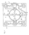
- Fig. 1 shows a plan view of the land mine according to the invention with the housing cover removed
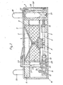
- Fig. 2 shows a section along the line II-II in Fig. 1
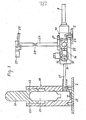
- Fig. 3 is a schematic representation of the ignition system in a partially sectioned side view.
- the land mine shown has a rectangular housing 1, which is composed of a base plate 2 and a cover 3.
- Two explosive charges are accommodated in the housing 1, e.g. a so-called hollow charge 4 in a chamber located in the center of the housing 1, which is closed at the top by a funnel-shaped boundary wall 5.
- This hollow charge 4 has an armor-piercing effect and achieves its greatest penetration force if there is a distance of approximately 50 to 70 cm between the mine and the armor plate to be penetrated.
- An annular chamber is provided concentrically around the shaped charge 4, in which there is a so-called blow charge 6, which acts primarily on the chain of an armored vehicle.
- the primer charge 7 which is assigned detonators 8 and which ensures reliable ignition the explosive charges 4 and 6 causes.
- the two charges 4 and 6 are connected to one another by openings 9 in the partition between the chambers containing them.
- detonators 8 are independent of one another and each assigned to a different ignition system. There are therefore four independent detonators, etc. a pressure igniter 10, a kink igniter 11, a relief igniter 12 and a side ignition channel 13, in which e.g. an explosive device that can be triggered electrically, electronically, by vibrations in the floor or by changes in the magnetic field or the induction field can be used.
- a pressure igniter 10 e.g. an explosive device that can be triggered electrically, electronically, by vibrations in the floor or by changes in the magnetic field or the induction field can be used.
- Each detonator is equipped with a safety device that can be used to either secure or unlock it.
- the pressure igniter 10 is designed as a pneumatic pressure igniter. 2 and 3, the firing pin 14 is arranged on a piston 14 1 , which is held in its rest position by a spring-loaded ball 15 which engages in a locking groove of the piston 14 1 .
- the piston 14 ' is actuated pneumatically and is displaceable in a cylinder 16 which is connected via lines 17 to four triggering devices 18 which are arranged in the corners of the housing 1 according to FIG. 1. From FIGS. 2 and 3 it can be seen that each trigger device 18 has a pressure stamp 19 which, when loaded, presses a gas cartridge 20 against a mandrel 21 which opens the gas seal of the cartridge 20. Around To prevent false triggering with small pressure loads, each pressure stamp 19 is secured by shear pins 22.
- the gas cartridge 20 is pressed against the mandrel 21 and thus opened.
- the then outflowing compressed gas passes through line 17 into cylinder 16, where, after overcoming the holding force of ball 15, it displaces piston 14 1 and, with it, firing pin 14, to which a primer 23 is assigned.
- the locking pin 24 is rotatable in the housing of the pressure igniter 10 about an axis extending transversely to the direction of movement of the firing pin 14 with the aid of a shaft 26, which via a on the outside of the cover 2 lying hand lever 27 can be actuated.
- This hand lever 27 can be secured by a split pin 29 shown in FIG. 3.
- the locking pin 24 prevents the firing pin 14 from striking the primer 23. Only after turning the locking pin 24 through 90 ° can the firing pin 14 reach the primer 23 through the bore 25.
- the shaft 26 is provided with a predetermined breaking point 28, after which the ignition system can no longer be secured by means of the hand lever 27. Securing is then only possible by using a special key that is attached to the remaining stub shaft.
- the pneumatic detonator provided according to the invention can be arranged in a mine together with other detonators be as shown and described in the exemplary embodiment.
- the pneumatic igniter can also be used as the only igniter in a land mine, and the number of triggering devices can be freely selected as required. Since only one line for the pressure medium is required between the release device and the igniter, the release devices can be arranged at any point in the mine housing in accordance with the respective requirements.
Landscapes
- Engineering & Computer Science (AREA)
- General Engineering & Computer Science (AREA)
- Air Bags (AREA)
- Emergency Lowering Means (AREA)
- Portable Nailing Machines And Staplers (AREA)
Applications Claiming Priority (2)
| Application Number | Priority Date | Filing Date | Title |
|---|---|---|---|
| AT3746/82 | 1982-10-11 | ||
| AT374682A AT384673B (de) | 1982-10-11 | 1982-10-11 | Landmine, insbesondere zur panzerabwehr |
Publications (2)
| Publication Number | Publication Date |
|---|---|
| EP0108742A1 true EP0108742A1 (fr) | 1984-05-16 |
| EP0108742B1 EP0108742B1 (fr) | 1987-02-04 |
Family
ID=3554840
Family Applications (2)
| Application Number | Title | Priority Date | Filing Date |
|---|---|---|---|
| EP19830890177 Expired EP0107643B1 (fr) | 1982-10-11 | 1983-10-10 | Mine terrestre, notamment antichar |
| EP83890178A Expired EP0108742B1 (fr) | 1982-10-11 | 1983-10-10 | Mine terrestre, notamment mine antichar |
Family Applications Before (1)
| Application Number | Title | Priority Date | Filing Date |
|---|---|---|---|
| EP19830890177 Expired EP0107643B1 (fr) | 1982-10-11 | 1983-10-10 | Mine terrestre, notamment antichar |
Country Status (3)
| Country | Link |
|---|---|
| EP (2) | EP0107643B1 (fr) |
| AT (1) | AT384673B (fr) |
| DE (2) | DE3372662D1 (fr) |
Citations (4)
| Publication number | Priority date | Publication date | Assignee | Title |
|---|---|---|---|---|
| DE959257C (de) * | 1951-08-04 | 1957-02-28 | Montedison Spa | Druckzuender mit Bruchampulle fuer unmagnetische Landminen |
| DE1199665B (de) * | 1962-05-26 | 1965-08-26 | Karlsruhe Augsburg Iweka | Metallfreier Zuender fuer Minen |
| FR2393261A1 (fr) * | 1977-06-01 | 1978-12-29 | Ruggieri Ets | Mine indetectable pour chenille |
| CH634406A5 (de) * | 1976-09-30 | 1983-01-31 | Ffv Mipro Ab | Minenzuendvorrichtung. |
Family Cites Families (9)
| Publication number | Priority date | Publication date | Assignee | Title |
|---|---|---|---|---|
| US830538A (en) * | 1904-08-19 | 1906-09-11 | Albert H Stebbins | Pneumatic vanner. |
| FR1355501A (fr) * | 1950-08-11 | 1964-03-20 | Alsacienne D Explosifs Et D Ap | Engins explosifs |
| FR1053566A (fr) * | 1952-04-08 | 1954-02-03 | Commerce Internat Soc Et | Perfectionnements apportés aux mines explosives, notamment aux mines antichars |
| US3410212A (en) * | 1953-05-07 | 1968-11-12 | Army Usa | Anti-tank mine with binary explosive charge |
| US2830538A (en) * | 1953-07-31 | 1958-04-15 | Albert O Dodge | Automatic firing device |
| FR1605223A (fr) * | 1965-06-03 | 1973-08-31 | ||
| SE373660B (sv) * | 1973-05-22 | 1975-02-10 | Bofors Ab | Landmina |
| FR2507307A1 (fr) * | 1981-06-03 | 1982-12-10 | Trt Telecom Radio Electr | Procede de mise a feu d'engin explosif et engin explosif ainsi obtenu |
| AT371932B (de) * | 1981-11-12 | 1983-08-10 | Assmann Geb | Panzermine |
-
1982
- 1982-10-11 AT AT374682A patent/AT384673B/de not_active IP Right Cessation
-
1983
- 1983-10-10 DE DE8383890177T patent/DE3372662D1/de not_active Expired
- 1983-10-10 DE DE8383890178T patent/DE3369727D1/de not_active Expired
- 1983-10-10 EP EP19830890177 patent/EP0107643B1/fr not_active Expired
- 1983-10-10 EP EP83890178A patent/EP0108742B1/fr not_active Expired
Patent Citations (4)
| Publication number | Priority date | Publication date | Assignee | Title |
|---|---|---|---|---|
| DE959257C (de) * | 1951-08-04 | 1957-02-28 | Montedison Spa | Druckzuender mit Bruchampulle fuer unmagnetische Landminen |
| DE1199665B (de) * | 1962-05-26 | 1965-08-26 | Karlsruhe Augsburg Iweka | Metallfreier Zuender fuer Minen |
| CH634406A5 (de) * | 1976-09-30 | 1983-01-31 | Ffv Mipro Ab | Minenzuendvorrichtung. |
| FR2393261A1 (fr) * | 1977-06-01 | 1978-12-29 | Ruggieri Ets | Mine indetectable pour chenille |
Also Published As
| Publication number | Publication date |
|---|---|
| ATA374682A (de) | 1987-05-15 |
| AT384673B (de) | 1987-12-28 |
| EP0107643A1 (fr) | 1984-05-02 |
| DE3369727D1 (en) | 1987-03-12 |
| EP0108742B1 (fr) | 1987-02-04 |
| DE3372662D1 (en) | 1987-08-27 |
| EP0107643B1 (fr) | 1987-07-22 |
Similar Documents
| Publication | Publication Date | Title |
|---|---|---|
| EP0158700B1 (fr) | Fusée pour projectile secondaire | |
| DE2907309C2 (de) | Aus einem Geschoß auszustoßendes Tochtergeschoß | |
| DE1578457B2 (de) | Sicherungseinrichtung fuer aufschlagzuender | |
| DE3321191C2 (de) | Sicherheitseinrichtung für einen Geschoßzünder | |
| DE2318039A1 (de) | Annaeherungszuender | |
| EP0435083A2 (fr) | Antenne d'allumage à distance réglable pour une tête de combat à charge creuse, commutable entre modes d'opération de pénétration ou d'élargissement | |
| DE2750018A1 (de) | Sicherungsklappe fuer zuend- und leuchtspursaetze | |
| EP0108742B1 (fr) | Mine terrestre, notamment mine antichar | |
| DE958183C (de) | Aufschlagzuender mit oder ohne Verzoegerung | |
| DE2106476B2 (de) | Sicherheitsvorrichtung fuer einen zuender fuer mit festen treibstoffen betriebene strahltriebwerke, insbesondere fuer feststoffraketentriebwerke | |
| DE2426838A1 (de) | Aufschlagzuender | |
| DE1084618B (de) | Zuender fuer Raketengeschosse | |
| DE1553866B2 (de) | Abschußvorrichtung für ein Geschoß | |
| DE3315560C2 (fr) | ||
| DE2303241A1 (de) | Unmagnetische schuetzenmine fuer den kriegseinsatz | |
| DE1183409B (de) | Zerlegerzuender fuer Drallgeschosse mit Vorrohrsicherheit | |
| DE1946991A1 (de) | Hohlladung | |
| DE102013000050B3 (de) | Selbstzerlegungsmechanimus für einen Zünder | |
| DE312110C (fr) | ||
| DE2453267C3 (de) | Zündvorrichtung für ein Explosivgeschoß | |
| DE515458C (de) | Zuender fuer Minen u. dgl. | |
| DE195738C (fr) | ||
| AT393561B (de) | Sicherungsvorrichtung fuer landminen | |
| DE197304C (fr) | ||
| AT30517B (de) | Zündersicherung für Sprenggeschosse. |
Legal Events
| Date | Code | Title | Description |
|---|---|---|---|
| PUAI | Public reference made under article 153(3) epc to a published international application that has entered the european phase |
Free format text: ORIGINAL CODE: 0009012 |
|
| AK | Designated contracting states |
Designated state(s): BE CH DE FR GB IT LI NL SE |
|
| 17P | Request for examination filed |
Effective date: 19841023 |
|
| GRAA | (expected) grant |
Free format text: ORIGINAL CODE: 0009210 |
|
| AK | Designated contracting states |
Kind code of ref document: B1 Designated state(s): BE CH DE FR GB IT LI NL SE |
|
| PG25 | Lapsed in a contracting state [announced via postgrant information from national office to epo] |
Ref country code: NL Effective date: 19870204 Ref country code: IT Free format text: LAPSE BECAUSE OF FAILURE TO SUBMIT A TRANSLATION OF THE DESCRIPTION OR TO PAY THE FEE WITHIN THE PRESCRIBED TIME-LIMIT;WARNING: LAPSES OF ITALIAN PATENTS WITH EFFECTIVE DATE BEFORE 2007 MAY HAVE OCCURRED AT ANY TIME BEFORE 2007. THE CORRECT EFFECTIVE DATE MAY BE DIFFERENT FROM THE ONE RECORDED. Effective date: 19870204 Ref country code: FR Free format text: THE PATENT HAS BEEN ANNULLED BY A DECISION OF A NATIONAL AUTHORITY Effective date: 19870204 Ref country code: BE Effective date: 19870204 |
|
| PG25 | Lapsed in a contracting state [announced via postgrant information from national office to epo] |
Ref country code: SE Effective date: 19870228 |
|
| REF | Corresponds to: |
Ref document number: 3369727 Country of ref document: DE Date of ref document: 19870312 |
|
| EN | Fr: translation not filed | ||
| NLV1 | Nl: lapsed or annulled due to failure to fulfill the requirements of art. 29p and 29m of the patents act | ||
| PLBE | No opposition filed within time limit |
Free format text: ORIGINAL CODE: 0009261 |
|
| STAA | Information on the status of an ep patent application or granted ep patent |
Free format text: STATUS: NO OPPOSITION FILED WITHIN TIME LIMIT |
|
| 26N | No opposition filed | ||
| PG25 | Lapsed in a contracting state [announced via postgrant information from national office to epo] |
Ref country code: GB Effective date: 19881010 |
|
| PG25 | Lapsed in a contracting state [announced via postgrant information from national office to epo] |
Ref country code: LI Effective date: 19881031 Ref country code: CH Effective date: 19881031 |
|
| REG | Reference to a national code |
Ref country code: CH Ref legal event code: PL |
|
| PG25 | Lapsed in a contracting state [announced via postgrant information from national office to epo] |
Ref country code: DE Effective date: 19890701 |
|
| GBPC | Gb: european patent ceased through non-payment of renewal fee |