EP0108829B1 - Axialkompensator - Google Patents
Axialkompensator Download PDFInfo
- Publication number
- EP0108829B1 EP0108829B1 EP82110552A EP82110552A EP0108829B1 EP 0108829 B1 EP0108829 B1 EP 0108829B1 EP 82110552 A EP82110552 A EP 82110552A EP 82110552 A EP82110552 A EP 82110552A EP 0108829 B1 EP0108829 B1 EP 0108829B1
- Authority
- EP
- European Patent Office
- Prior art keywords
- shape
- attachments
- pipe section
- pipe
- recesses
- Prior art date
- Legal status (The legal status is an assumption and is not a legal conclusion. Google has not performed a legal analysis and makes no representation as to the accuracy of the status listed.)
- Expired
Links
- 239000002184 metal Substances 0.000 claims abstract description 7
- 238000010276 construction Methods 0.000 claims abstract description 4
- 238000010438 heat treatment Methods 0.000 claims abstract description 4
- 238000013459 approach Methods 0.000 description 8
- 230000015572 biosynthetic process Effects 0.000 description 6
- 238000005755 formation reaction Methods 0.000 description 6
- 230000008878 coupling Effects 0.000 description 5
- 238000010168 coupling process Methods 0.000 description 5
- 238000005859 coupling reaction Methods 0.000 description 5
- 230000005540 biological transmission Effects 0.000 description 3
- 238000006073 displacement reaction Methods 0.000 description 2
- 239000007787 solid Substances 0.000 description 2
- 230000000295 complement effect Effects 0.000 description 1
- 230000008602 contraction Effects 0.000 description 1
- 238000005516 engineering process Methods 0.000 description 1
- 238000003780 insertion Methods 0.000 description 1
- 230000037431 insertion Effects 0.000 description 1
- 238000004519 manufacturing process Methods 0.000 description 1
- 230000001681 protective effect Effects 0.000 description 1
- 125000006850 spacer group Chemical group 0.000 description 1
Images
Classifications
-
- F—MECHANICAL ENGINEERING; LIGHTING; HEATING; WEAPONS; BLASTING
- F16—ENGINEERING ELEMENTS AND UNITS; GENERAL MEASURES FOR PRODUCING AND MAINTAINING EFFECTIVE FUNCTIONING OF MACHINES OR INSTALLATIONS; THERMAL INSULATION IN GENERAL
- F16L—PIPES; JOINTS OR FITTINGS FOR PIPES; SUPPORTS FOR PIPES, CABLES OR PROTECTIVE TUBING; MEANS FOR THERMAL INSULATION IN GENERAL
- F16L51/00—Expansion-compensation arrangements for pipe-lines
- F16L51/02—Expansion-compensation arrangements for pipe-lines making use of a bellows or an expansible folded or corrugated tube
Definitions
- the invention relates to an axial compensator for insertion into a pipeline, such as a district heating pipe, with at least one metal bellows, the ends of which are connected to a pipe section, the mutually facing ends of the pipe sections being axially displaceable, interlocking formations, each with at least three circumferentially of the pipe section arranged form approaches and arranged between adjacent form approaches form recesses.
- one or more compensators are installed between two fixed points in order to absorb the linear expansion of the pipes. Fixed points can be saved by using more than one compensator. The problem arises, however, that one of the compensators is excessively loaded when there are changes in length in the pipe system, without first loading the other or the other compensators.
- stops are provided as stroke limits.
- an axial compensator is provided, in which an annular flange is first formed on a piece of pipe or pipe socket, to which one end of a flexible bellows is attached.
- a pipe part with a slightly larger inner diameter than the inner diameter of the ring flange extends from the pipe flange. Furthermore, a protective jacket surrounding the bellows is attached to this ring flange. The bellows is still attached at its other end to another ring flange which surrounds another piece of pipe. On the side of the flange opposite the point of attachment of the bellows to this flange, a ring is slidably placed on the further piece of pipe, which is firmly connected to the jacket. To prevent rotation, rails are attached to the other pipe section, which guide the retaining ring for the jacket with grooves. When the bellows is pressed together, the further piece of pipe abuts the first-mentioned flange with an end protruding into the bellows. When the bellows is pulled apart, the ring connected to the jacket limits the stroke.
- a device of another type which is used as a pipe coupling (US-A-2 890 066)
- two coupling elements are provided, each of which has an anchor-like cutout at their ends, as a result of which protruding lugs engage behind when the coupling elements are coupled in to make the connection.
- a sliding sleeve concentrically surrounding the two coupling elements secures them in their engagement position against radial misalignment.
- Couplings of this type are used for pipelines that can be quickly coupled and uncoupled, but cannot absorb considerable pressure or tensile forces or large torsional forces.
- a generic axial compensator with a metal bellows is known from US-A-2 958 550.
- This compensator is formed from connectors that are provided with formations.
- the formations are provided on the circumference with constant mutually arranged finger-like extensions with complementary recesses arranged between them.
- the interlocking extensions prevent mutual rotation of the connecting pieces or the metal bellows connecting them.
- Arranged on the inside of the extensions of each connector is a ring fixed by means of fastening screws, on the outside of which the extensions of the other connector are slidably guided.
- the rings act as limit stops when pulling apart the compensator.
- the elements such as the flanges, the jacket and the ring connected to them, must be solid and heavy to absorb the large tensile or compressive forces. This can easily damage or tear the rings, so that the functional reliability of the compensator is no longer guaranteed.
- Stable welded connections must also be provided between the large number of individual elements via which the forces are transmitted.
- the deflection of the forces in such a compensator is disadvantageous, apart from the considerable construction effort, which also includes the separate anti-rotation device.
- the invention is therefore based on the object of developing the generic compensator mentioned above in such a way that it is simpler in terms of production technology and has a functionally reliable limitation for pulling apart the compensator and, in addition, all occurring forces are transmitted directly without deflection.
- this object is achieved in that the form approaches are T-shaped and these are also associated with T-shaped form recesses, that the depth determined by the T-crossbar of the form recesses is more than twice the height of the T-crossbar is of the respective mold approach and that the cooperating mold approaches and recesses engage behind each other, the forces occurring directly from one pipe section to the other transmitting mold approaches are integrally formed with this.
- the bellows is preferably arranged outside the pipe sections, in principle a different design could also be chosen, in which the pipe sections with their formations are therefore provided outside the bellows.
- the bellows can be attached directly to the pipe pieces if its outer shafts project radially inwards to the outer circumference of the pipe pieces. But it can also be attached to the pipe pieces rings on which the ends of the bellows are fixed. However, these rings can be small and therefore light, since they do not have to transmit tensile and shear forces, but only serve to hold the bellows.
- a jacket can additionally be provided around the bellows in a conventional manner, which is fixedly connected to the one piece of pipe by means of an annular flange, while on spacers which are connected to the other piece of pipe and, for example, can also be designed in the form of a ring Movements glides.
- a preferred embodiment in which the depth of the cross-bar-shaped area of the mold recess corresponds to the length of the T-web of the mold attachment, ensures that the attachments of both pipe sections strike the bottoms of the recesses of the corresponding other pipe section when the compensator is pushed together, so that not only the lugs on a pipe section have to absorb the forces.
- At least one ring is attached to the inner and / or outer wall of the pipe section in the area of the formations at least on one pipe section.
- Such a ring is of course only firmly connected to the lugs of one pipe section, while it slides relative to the lugs of the other pipe section.
- these rings are alternately connected to one or the other piece of pipe, and if adjacent rings are arranged on one side of the pipes, either outside or inside, which is both possible, the distance of the length is just the maximum possible Stroke corresponds.
- the rings themselves do not have to absorb any tensile or compressive forces and are therefore designed to be correspondingly narrow, so that they represent almost no resistance to the flow.
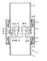
- the axial compensator 1 has two pipe sections 2 and 3. Ring flanges 4 and 6 are placed on the pipe sections 2 and 3 and welded to the pipe sections, on which in turn the two ends 7, 8 of a metal bellows 9 are fastened. A further ring 11 is placed around the ring flange 4, on which a jacket 12 is attached, which extends from the ring 11 over the bellows 9 and over the ring flange 6 on the pipe section 3. To guide the casing 12, 6 guide supports 13 are arranged on the ring flange, which extend outwards below the inner circumference of the casing 12. Instead of the separately arranged guide supports, a corresponding guide ring could also be arranged around the ring flange 6. The jacket 12 serves to protect the bellows 9.
- the mutually adjacent ends 16, 17 of the pipe sections 2, 3 are provided with T-shaped, axially extending lugs 18, 19, a shaped recess 21, 22 being formed between two lugs 18 and 19 on a pipe end 16, 17 .
- the lugs 18, 19 engage in one another such that a crossbeam 23 of a lug 18 engages in a recess 22 and, with its regions of the crossbeam 23 projecting beyond the web 24, engages behind the corresponding regions of a crossbeam 26 on the other tube end 17.
- the bellows In the position shown in the figure, the bellows is pulled apart, the extended position being limited by the mutually behind cross bars 23, 26, which act as mutual stops.
- the cross beams on the bottoms 27, 28 of the beat mold recesses 21, 22 When completely pushed in position, the cross beams on the bottoms 27, 28 of the beat mold recesses 21, 22 and so limit the telescoping of the - compensator. In both cases, the forces are transmitted linearly from one pipe section to the other pipe section without any deflection.
- the mutually engaging lugs 18, 19 secure the two pipe sections 22, 23 and thus the bellows 9 against rotation, and thus act as a torsion lock.
- rings 31, 32 are also provided around the lugs 18, 19, the ring 32 being connected, for example, to the lugs 19 and the ring 31 being connected to the lugs 18.
- the rings serve as an additional safeguard. They slide in each case on the approaches of the other pipe section, whereby they do not interfere with the mutual axial movement of the pipe sections 2, 3, but have such an axial distance that the intended stroke is fully utilized during movements without the rings touching.
Landscapes
- Engineering & Computer Science (AREA)
- General Engineering & Computer Science (AREA)
- Mechanical Engineering (AREA)
- Joints Allowing Movement (AREA)
- Structures Of Non-Positive Displacement Pumps (AREA)
- Mutual Connection Of Rods And Tubes (AREA)
- Transition And Organic Metals Composition Catalysts For Addition Polymerization (AREA)
- Devices For Conveying Motion By Means Of Endless Flexible Members (AREA)
- Vibration Prevention Devices (AREA)
- Vehicle Body Suspensions (AREA)
- Glass Compositions (AREA)
- Control Of High-Frequency Heating Circuits (AREA)
Description
- Die Erfindung betrifft einen Axialkompensator zum Einsetzen in eine Rohrleitung, wie eine Fernheizungsleitung, mit mindestens einem Metallbalg, dessen Enden mit jeweils einem Rohrstück verbunden sind, wobei die einander zugewandten Enden der Rohrstücke axial gegeneinander verschiebbare, ineinander greifende Formausbildungen mit jeweils wenigstens drei über den Umfang des Rohrstücks angeordneten Formansätzen und zwischen benachbarten Formansätzen angeordnete Formausnehmungen aufweisen.
- In Rohrleitungen, wie Fernheizungsleitungen, werden zwischen zwei Festpunkten ein oder mehrere Kompensatoren eingebaut, um Längenausdehnungen der Rohrleitungen aufzunehmen. Durch den Einsatz von mehr als einem Kompensator können Festpunkte eingespart werden. Es ergibt sich aber hierbei das Problem, daß einer der Kompensatoren bei Längenänderungen im Rohrsystem übermäßig belastet wird, ohne daß zunächst der andere oder die anderen Kompensatoren belastet werden. Um eine Überbelastung auf Zug oder Schub eines Kompensators zu vermeiden bzw. das Auseinanderziehen oder Zusammenschieben eines Kompensators zu begrenzen, werden Anschläge als Hubbegrenzungen vorgesehen. So ist in der WO-A- 82 01 759 ein Axialkompensator vorgesehen, bei dem an einem Rohrstück oder Rohrstutzen zunächst ein ringförmiger Flansch ausgebildet ist, an dem das eine Ende eines flexiblen Balges befestigt ist. Innerhalb des Balges erstreckt sich vom Rohrflansch ein Rohrteil mit einem etwas größeren Innendurchmesser als der Innendurchmesser des Ringflansches. Weiterhin ist an diesem Ringflansch ein den Balg umgebender und schützender Mantel befestigt. Der Balg ist weiterhin mit seinem anderen Ende an einem weiteren Ringflansch befestigt, der ein weiteres Rohrstück umgibt. Auf der dem Befestigungspunkt des Balgs an diesem Flansch entgegengesetzten Seite des Flansches ist gleitend auf dem weiteren Rohrstück ein Ring aufgesetzt, der mit dem Mantel fest verbunden ist. Zur Verdrehsicherung sind auf dem weiteren Rohrstück Schienen befestigt, die mit Nuten den Haltering für den Mantel führen. Beim Zusammendrücken des Balges stößt das weitere Rohrstück mit einem in den Balg hineinragenden Ende am erstgenannten Flansch an. Beim Auseinanderziehen des Balges begrenzt der mit dem Mantel verbundene Ring den Hub.
- Bei einer Vorrichtung anderer Art, die als Rohrkupplung verwendet wird (US-A- 2 890 066), sind zwei Kupplungselemente vorgesehen, die an ihren Enden jeweils einen ankerartigen Ausschnitt aufweisen, wodurch bei eingekuppelten Kupplungselementen sich überstehende Ansätze hintergreifen, um die Verbindung herzustellen. Eine konzentrisch die beiden Kupplungselemente umgebende Schiebehülse sichert diese in ihrer sich hintergreifenden Lage gegen radialen Versatz. Kupplungen dieser Art werden bei Rohrleitungen verwendet, die schnell ein- und auszukuppeln sind, können aber weder erheblichen Druck- oder Zugkräfte noch große Torsionskräfte aufnehmen.
- Ein gattungsgemäßer Axialkompensator mit einem Metallbalg ist aus der US-A- 2 958 550 bekannt. Dieser Kompensator wird aus Anschlußstücken gebildet, die mit Ausformungen versehen sind. Die Ausformungen sind umfangsseitig mit konstanten gegenseitig angeordneten fingerartigen Fortsätzen mit dazwischen angeordneten komplementären Ausnehmungen versehen. Die ineinandergreifenden Fortsätze verhindern eine gegenseitige Verdrehung der Anschlußstücke bzw. des diese verbindenden Metallbalgs. An der Innenseite der Fortsätze jedes Anschlußstücks ist ein mittels Befestigungsschrauben fixierter Ring angeordnet, auf dessen Außenseite die Fortsätze des anderen Anschlußstücks gleitend geführt sind. Die Ringe wirken als Begrenzungsanschläge beim Auseinanderziehen des Kompensators. Auch hier müssen zur Aufnahme der großen Zug-oder Druckkräfte die Elemente, wie die Flansche, der Mantel sowie der mit diesem verbundene Ring massiv und schwer ausgebildet sein. Dies kann leicht zur Beschädigung oder zum Ausreißen der Ringe führen, so daß die Funktionssicherheit des Kompensators nicht mehr gewährleistet ist.
- Ebenfalls müssen zwischen der Vielzahl der einzelnen Elemente, über die die Kräfte übertragen werden, stabile Schweißverbindungen vorgesehen sein. Insbesondere ist aber auch die Umlenkung der Kräfte bei einem solchen Kompensator nachteilig, abgesehen von dem erheblichen konstruktiven Aufwand, wozu auch die separate Verdrehsicherung zählt.
- Der Erfindung liegt daher die Aufgabe zugrunde, den zuvor genannten gattungsgemäßen Kompensator so weiterzubilden, daß er fertigungstechnisch einfacher ausgebildet ist und dabei eine funktionssichere Begrenzung für ein Auseinanderziehen des Kompensators aufweist und darüber hinaus alle auftretenden Kräfte direkt ohne Umlenkung übertragen werden.
- Erfindungsgemäß wird die genannte Aufgabe dadurch gelöst, daß die Formansätze T-förmig ausgebildet sind und diesen ebenfalls T-förmige Formausnehmungen zugeordnet sind, daß die durch den T-Querbalken der Formausnehmungen bestimmte Tiefe derselben mehr als doppelt so groß wie die Höhe des T-Querbalkens des jeweiligen Formansatzes ist und daß sich die zusammenwirkenden Formansätze und Formausnehmungen gegenseitig hintergreifen, wobei die die auftretenden Kräfte direkt vom einen Rohrstück zum anderen übertragenden Formansätze einstückig mit diesem ausgebildet sind.
- Durch diese Formausbildungen an den einander zugewandten bzw. benachbarten Enden der Rohrstücke selbst wird gleichzeitig eine Sicherung gegen zu starkes Zusammendrücken des Balges, zu weites Auseinanderziehen des Balges, also eine Hubsicherung in beiden Richtungen und zusätzlich eine Verdrehsicherung geschaffen. Es sind keine zusätzlichen Kraftübertragungselemente erforderlich, wie beim Stand der Technik, wo diese massiv und stabil ausgebildet sein mußten. Die Kräfte werden insbesondere direkt von einem Rohrstück auf das andere Rohrstück ohne Zwischenelemente übertragen. Dies wird dadurch bewirkt, daß die beiden Rohrenden dabei derart gegeneinander gleitend oder verschiebbar verbunden sind, daß die Querbalken der T-förmigen Ansätze einander hintergreifen, wodurch eine Sicherung gegen zu starkes Auseinanderziehen gewährleistet wird, während beim Zusammenschieben das vordere Ende eines derartigen T-Querbalkens am Boden der entsprechenden Formausnehmung des anderen Rohrstücks anschlägt. Weiterhin wird durch die einstückige Ausbildung der Formansätze und der Rohrstücke neben der Drehsicherung auch eine Übertragung von Radialkräften ohne zusätzliche Kraftübertragungselemente gewährleistet.
- Vorzugsweise ist der Balg außerhalb der Rohrstücke angeordnet, grundsätzlich könnte auch eine andersartige Ausgestaltung gewählt werden, bei dem also die Rohrstücke mit ihren Formausbildungen außerhalb des Balges vorgesehen sind. Der Balg kann bei einer koaxial um die Rohrstücke vorgesehenen Ausbildung direkt an diesem befestigt sein, wenn seine äußeren Wellen radial nach innen bis zum Außenumfang der Rohrstücke ragen. Es können aber auch auf den Rohrstücken Ringe befestigt sein, an denen die Enden des Balges festgelegt sind. Diese Ringe können aber klein und damit leicht ausgeführt sein, da sie keine Zug- und Schubkräfte übertragen müssen, sondern lediglich dazu dienen, den Balg zu halten. Um den Balg kann bei einer solchen Ausgestaltung zusätzlich in üblicher Weise ein Mantel vorgesehen sein, der mit dem einen Rohrstück durch einen Ringflansch fest verbunden ist, während er auf Abstandhaltern, die mit dem anderen Rohrstück verbunden sind und beispielsweise auch ringförmig ausgestaltet sein können, bei Bewegungen gleitet.
- Durch eine bevorzugte Ausgestaltung, bei der die Tiefe des querbalkenförmigen Bereichs der Formausnehmung der Länge des T-Stegs des Formansatzes entspricht, wird erreicht, daß gleichzeitig die Ansätze beider Rohrstücke an den Böden der Ausnehmungen des entsprechenden anderen Rohrstückes anschlagen, wenn der Kompensator zusammengeschoben ist, so daß nicht nur die Ansätze an einem Rohrstück die Kräfte aufnehmen müssen.
- Es hat sich gezeigt, daß ein radiales Versetzen der Rohrstücke gegeneinander auch bei höchsten Belastungen nicht auftritt. Sicherheitshalber kann aber vorgesehen sein, daß im Bereich der Formausbildungen zumindest an einem Rohrstück an der Innen- und/oder Außenwandung des Rohrstücks mindestens ein Ring befestigt ist. Ein solcher Ring ist selbstverständlich nur mit den Ansätzen eines Rohrstücks fest verbunden, während er relativ zu den Ansätzen des anderen Rohrstücks gleitet. Sind mehrere Ringe vorgesehen, so sind diese wechselweise mit dem einen oder anderen Rohrstück verbunden, wobei, soweit benachbarte Ringe auf einer Seite der Rohre, also entweder außen oder innen, was beides möglich ist, angeordnet sind, der Abstand der Länge gerade dem maximal möglichen Hub entspricht. Die Ringe müssen selbst keinerlei Zug- oder Druckkräfte aufnehmen und sind deshalb entsprechend schmal ausgebildet, so daß sie nahezu keinen Widerstand für die Strömung darstellen.
- Ein Ausführungsbeispiel des erfindungsgemäßen Axialkompensators wird nashstehend unter Bezugnahme auf die Zeichnung im einzelnen erläutert. Dabei zeigt die einzige Figur
- einen erfindungsgemäßen Axialkompensator im Längsschnitt.
- Der dargestellte erfindungsgemäße Axialkompensator 1 weist zwei Rohrstücke 2 und 3 auf. Auf den Rohrstücken 2 und 3 sind Ringflansche 4 und 6 aufgesetzt und mit den Rohrstücken verschweißt, an denen wiederum die beiden Enden 7, 8 eines Metallbalgs 9 befestigt sind. Um den Ringflansch 4 ist ein weiterer Ring 11 gelegt, auf dem ein Mantel 12 befestigt ist, der sich von dem Ring 11 über den Balg 9 und über den Ringflansch 6 auf dem Rohrstück 3 hinaus erstreckt. Zur Führung des Mantels 12 sind auf dem Ringflansch 6 Führungsstützen 13 angeordnet, die sich bis unterhalb des Innenumfangs des Mantels 12 nach außen erstrekken. Statt der separat angeordneten Führungsstützen könnte auch ein entsprechender Führungsring um den Ringflansch 6 angeordnet sein. Der Mantel 12 dient zum Schutz des Balges 9.
- Die einander benachbarten Enden 16, 17 der Rohrstücke 2, 3 sind mit T-förmig ausgestalteten, sich axial erstreckenden Ansätzen 18, 19 versehen, wobei zwischen jeweils zwei Ansätzen 18 bzw. 19 an einem Rohrende 16, 17 eine Formausnehmung 21, 22 ausgebildet ist. Die Ansätze 18, 19 greifen derart ineinander, daß ein Querbalken 23 eines Ansatzes 18 in eine Ausnehmung 22 eingreift und dabei mit seinen über den Steg 24 hinausragenden Bereichen des Querbalkens 23 die entsprechenden Bereiche eines Querbalkens 26 am anderen Rohrende 17 hintergreift.
- Bei der in der Figur gezeigten Stellung ist der Balg auseinandergezogen, wobei die ausei nandergezogene Stellung durch die einander hintergrei fenden Querbalken 23, 26 begrenzt wird, die als wechselseitige Anschläge wirken. Bei völlig eingeschobener Stellung schlagen die Querbalken an den Böden 27, 28 der Formausnehmungen 21, 22 an und begrenzen so das Zusammenschieben des-Kompensators. In beiden Fällen werden die Kräfte linear, ohne jegliche Umlenkung von einem Rohrstück zum anderen Rohrstück übertragen. Gleichzeitig sichern die einander hintergreifenden Ansätze 18, 19 die beiden Rohrstücke 22, 23 und damit den Balg 9 gegen Verdrehungen, wirken also als Torsionssicherung.
- Bei der dargestellten Ausführungsform eines Axialkompensators sind noch um die Ansätze 18, 19 herum Ringe 31, 32 vorgesehen, wobei der Ring 32 beispielsweise mit den Ansätzen 19 und der Ring 31 mit den Ansätzen 18 verbunden ist. Obwohl auch ohne solche Ringe ein gegenseitiges Versetzen der Rohrstücke 2, 3 nicht beobachtet wurde, dienen die Ringe als zusätzliche Sicherung. Sie gleiten jeweils auf den Ansätzen des anderen Rohrstücks, wobei sie sich bei der gegenseitigen axialen Bewegung der Rohrstücke 2, 3 nicht behindern, sondern einen solchen axialen Abstand aufweisen, daß der vorgesehene Hub bei Bewegungen voll ausgenutzt wird, ohne das die Ringe sich berühren.
-
- 1 Axialkompensator
- 2 Rohrstück
- 3
- 4 Ringflansch
- 6
- 7 Ende (von 9)
- 8 " (von 9)
- 9 Metallbalg
- 11 Ring
- 12 Mantel
- 13 Führungsstützen
- 16 Enden
- 17
- 18 Ansatz
- 19
- 21 Formausnehmung
- 22
- 23 Querbalken
- 24 Steg
- 26 Querbalken
- 27 Boden
- 28
- 31 Ring
- 32
Claims (4)
daß die Formansätze (18, 19) T-förmig ausgebildet sind und diesen ebenfalls T-förmige Formausnehmungen (21, 22) zugeordnet sind, daß die durch den T-Querbalken der Formausnehmungen (21, 22) bestimmte Tiefe derselben mehr als doppelt so groß wie die Höhe des T-Querbalkens (23, 26) des jeweiligen Formansatzes (18, 19) ist, und daß sich die zusammenwirkenen Formansätze (18, 19) und Formausnehmungen (21, 22) gegenseitig hintergreifen, wobei die die auftretenden Kräfte direkt vom einen Rohrstück (2 bzw. 3) zum anderen (3 bzw. 2) übertragenden Formansätze (18, 19) einstückig mit diesem ausgebildet sind.
Priority Applications (6)
| Application Number | Priority Date | Filing Date | Title |
|---|---|---|---|
| DE8282110552T DE3276955D1 (en) | 1982-11-16 | 1982-11-16 | Axial compensator |
| AT82110552T ATE28928T1 (de) | 1982-11-16 | 1982-11-16 | Axialkompensator. |
| EP82110552A EP0108829B1 (de) | 1982-11-16 | 1982-11-16 | Axialkompensator |
| NO823879A NO156804C (no) | 1982-11-16 | 1982-11-19 | Aksialkompensator. |
| FI823973A FI75219C (fi) | 1982-11-16 | 1982-11-19 | Axialkompensator. |
| DK519782A DK150390C (da) | 1982-11-16 | 1982-11-22 | Aksialkompensator til anbringelse i en roerledning |
Applications Claiming Priority (1)
| Application Number | Priority Date | Filing Date | Title |
|---|---|---|---|
| EP82110552A EP0108829B1 (de) | 1982-11-16 | 1982-11-16 | Axialkompensator |
Publications (2)
| Publication Number | Publication Date |
|---|---|
| EP0108829A1 EP0108829A1 (de) | 1984-05-23 |
| EP0108829B1 true EP0108829B1 (de) | 1987-08-12 |
Family
ID=8189341
Family Applications (1)
| Application Number | Title | Priority Date | Filing Date |
|---|---|---|---|
| EP82110552A Expired EP0108829B1 (de) | 1982-11-16 | 1982-11-16 | Axialkompensator |
Country Status (6)
| Country | Link |
|---|---|
| EP (1) | EP0108829B1 (de) |
| AT (1) | ATE28928T1 (de) |
| DE (1) | DE3276955D1 (de) |
| DK (1) | DK150390C (de) |
| FI (1) | FI75219C (de) |
| NO (1) | NO156804C (de) |
Cited By (2)
| Publication number | Priority date | Publication date | Assignee | Title |
|---|---|---|---|---|
| CN104696660A (zh) * | 2015-03-27 | 2015-06-10 | 沈阳鑫博工业技术股份有限公司 | 双重轴向补偿型膨胀节 |
| CN107387924A (zh) * | 2017-08-16 | 2017-11-24 | 洛阳双瑞特种装备有限公司 | 一种用于膨胀节的具有导向功能的防扭转装置 |
Families Citing this family (10)
| Publication number | Priority date | Publication date | Assignee | Title |
|---|---|---|---|---|
| US5370427A (en) * | 1994-01-10 | 1994-12-06 | General Electric Company | Expansion joint for fluid piping with rotation prevention member |
| US5944363A (en) * | 1997-01-06 | 1999-08-31 | Senior Engineering Investments Ag | Flexible connector systems |
| DE19722967C1 (de) * | 1997-05-31 | 1998-08-20 | Hans Rattay | Axial-Kompensator |
| RU2122148C1 (ru) * | 1998-01-16 | 1998-11-20 | Закрытое акционерное общество "Теплосеть плюс" | Сильфонный компенсатор деформаций трубопроводов |
| US6109661A (en) * | 1999-04-16 | 2000-08-29 | Senior Engineering Investments Ag | Flexible coupler apparatus |
| US6568715B2 (en) | 2001-05-17 | 2003-05-27 | Senior Investments Ag | Vibration decoupling exhaust connector |
| US6921112B2 (en) * | 2002-11-26 | 2005-07-26 | Josif Atansoski | Exhaust vibration decoupling connector |
| CN102635751A (zh) * | 2012-03-30 | 2012-08-15 | 南通三创机械制造有限公司 | 高温膨胀节 |
| DE102013210982A1 (de) * | 2013-06-12 | 2014-12-18 | Bayerische Motoren Werke Aktiengesellschaft | Dehnkörper zur Verbindung von zwei Rohrstücken insbesondere eines Abgaskanals eines Kraftfahrzeugs sowie Abgasturboladereinheit mit einem derartigen Dehnkörper |
| CN111649187A (zh) * | 2020-07-09 | 2020-09-11 | 安徽九州云箭航天技术有限公司 | 一种具有内支撑的管道补偿器 |
Citations (7)
| Publication number | Priority date | Publication date | Assignee | Title |
|---|---|---|---|---|
| GB898383A (en) * | 1960-02-15 | 1962-06-06 | Teddington Aircraft Controls L | Improvements in fluid-tight expansion couplings incorporating flexible metallic bellows |
| FR1410746A (fr) * | 1963-10-16 | 1965-09-10 | Dispositif de montage pour compensateurs ou absorbeurs de dilatation dans les canalisations | |
| DE2249491A1 (de) * | 1971-12-16 | 1973-06-28 | Fischer Ag Georg | Axialkompensator fuer zwei zu verbindende rohre |
| DE2620334A1 (de) * | 1975-05-07 | 1976-11-18 | United Gas Industries Ltd | Selbsttaetig gefuehrter axialer rohrkompensator |
| GB1456668A (en) * | 1973-04-26 | 1976-11-24 | Rasmussen As E | Method of laying pipe systems for hot fluids such as subterra nean district heating pipe systems and a pipe system laid by the method |
| WO1982001759A1 (en) * | 1980-11-10 | 1982-05-27 | Bredahl Henning | Axial compensator |
| DE3200842A1 (de) * | 1982-01-14 | 1982-10-07 | Witzenmann GmbH, Metallschlauch-Fabrik Pforzheim, 7530 Pforzheim | Axialkompensator mit vorspanneinrichtung |
Family Cites Families (3)
| Publication number | Priority date | Publication date | Assignee | Title |
|---|---|---|---|---|
| US2890066A (en) * | 1956-08-20 | 1959-06-09 | Ralph L Kerr | Non-rotatable expansion coupling |
| US2958550A (en) * | 1958-04-17 | 1960-11-01 | Frank A Mcdonald | Bellows-type expansion compensator with anti-torque guide |
| US3907341A (en) * | 1974-10-23 | 1975-09-23 | Adolf Schoepe | Irrigation pipe and coupling construction |
-
1982
- 1982-11-16 EP EP82110552A patent/EP0108829B1/de not_active Expired
- 1982-11-16 DE DE8282110552T patent/DE3276955D1/de not_active Expired
- 1982-11-16 AT AT82110552T patent/ATE28928T1/de not_active IP Right Cessation
- 1982-11-19 NO NO823879A patent/NO156804C/no unknown
- 1982-11-19 FI FI823973A patent/FI75219C/fi not_active IP Right Cessation
- 1982-11-22 DK DK519782A patent/DK150390C/da active
Patent Citations (7)
| Publication number | Priority date | Publication date | Assignee | Title |
|---|---|---|---|---|
| GB898383A (en) * | 1960-02-15 | 1962-06-06 | Teddington Aircraft Controls L | Improvements in fluid-tight expansion couplings incorporating flexible metallic bellows |
| FR1410746A (fr) * | 1963-10-16 | 1965-09-10 | Dispositif de montage pour compensateurs ou absorbeurs de dilatation dans les canalisations | |
| DE2249491A1 (de) * | 1971-12-16 | 1973-06-28 | Fischer Ag Georg | Axialkompensator fuer zwei zu verbindende rohre |
| GB1456668A (en) * | 1973-04-26 | 1976-11-24 | Rasmussen As E | Method of laying pipe systems for hot fluids such as subterra nean district heating pipe systems and a pipe system laid by the method |
| DE2620334A1 (de) * | 1975-05-07 | 1976-11-18 | United Gas Industries Ltd | Selbsttaetig gefuehrter axialer rohrkompensator |
| WO1982001759A1 (en) * | 1980-11-10 | 1982-05-27 | Bredahl Henning | Axial compensator |
| DE3200842A1 (de) * | 1982-01-14 | 1982-10-07 | Witzenmann GmbH, Metallschlauch-Fabrik Pforzheim, 7530 Pforzheim | Axialkompensator mit vorspanneinrichtung |
Cited By (3)
| Publication number | Priority date | Publication date | Assignee | Title |
|---|---|---|---|---|
| CN104696660A (zh) * | 2015-03-27 | 2015-06-10 | 沈阳鑫博工业技术股份有限公司 | 双重轴向补偿型膨胀节 |
| CN104696660B (zh) * | 2015-03-27 | 2016-09-07 | 沈阳鑫博工业技术股份有限公司 | 双重轴向补偿型膨胀节 |
| CN107387924A (zh) * | 2017-08-16 | 2017-11-24 | 洛阳双瑞特种装备有限公司 | 一种用于膨胀节的具有导向功能的防扭转装置 |
Also Published As
| Publication number | Publication date |
|---|---|
| FI823973L (fi) | 1984-05-17 |
| NO156804C (no) | 1987-11-25 |
| FI75219B (fi) | 1988-01-29 |
| NO156804B (no) | 1987-08-17 |
| DK150390C (da) | 1987-10-12 |
| DK150390B (da) | 1987-02-16 |
| EP0108829A1 (de) | 1984-05-23 |
| FI75219C (fi) | 1988-05-09 |
| ATE28928T1 (de) | 1987-08-15 |
| NO823879L (no) | 1984-05-18 |
| DE3276955D1 (en) | 1987-09-17 |
| FI823973A0 (fi) | 1982-11-19 |
| DK519782A (da) | 1984-05-17 |
Similar Documents
| Publication | Publication Date | Title |
|---|---|---|
| DE69804365T2 (de) | Teleskopische und schwenkbare Rohrverbindung | |
| EP0108829B1 (de) | Axialkompensator | |
| DE69612342T2 (de) | Unlösbare Kabelkupplung mit Sprengring | |
| DE3334709C2 (de) | Teleskopwelle | |
| DE69911362T2 (de) | Anordnung zum Verbinden zweier rohrförmiger Elemente | |
| DE3307339C2 (de) | Selbstkuppelbare Gelenkwelle | |
| DE7612933U1 (de) | Kupplungsgehaeuse fuer lichtleitkabel | |
| EP3314148B1 (de) | Energieführungskette | |
| AT410706B (de) | Anschlussvorrichtung für ein kunststoffrohr | |
| EP0599780A1 (de) | Steckverbindung für Lichtwellenleiter | |
| EP2592287B1 (de) | Teleskopwelle mit Zugelement | |
| EP1305497B1 (de) | Gestängekupplung | |
| DE102008058042B4 (de) | Rohrkupplung für Rohre | |
| EP0641945B1 (de) | Betätigungszug für die Betätigung von Einrichtungen insbesondere in Fahrzeugen | |
| DE911195C (de) | Kupplungsvorrichtung fuer aneinandersteckbare Rohre | |
| DE202010013813U1 (de) | Schiebeelement zur Übertragung einer Schiebekraft auf ein Rohranschlusselement und Verbindungswerkzeug, das ein derartiges Schiebeelement umfasst | |
| DE102010007580A1 (de) | Endglied einer Energieführungskette | |
| CH689316A5 (de) | Optischer Stecker fuer eine Push/Pull-Steckverbindung. | |
| EP0458289A1 (de) | Verbindung für Bohrrohre od.dgl. | |
| EP3339927B1 (de) | Anschlusseinrichtung und glasfaserverteilerkasten | |
| EP3088136B1 (de) | Teleskopstiel für reinigungsgeräte | |
| DE2831186C2 (de) | Kugelgelenkige Rohrkupplung | |
| DE3241733C2 (de) | Vorrichtung zum Verbinden zweier Rohrenden | |
| WO2009130160A1 (de) | Optischer verbinder | |
| DE102017128175A1 (de) | Keilwellenverbindung an Mastsegment |
Legal Events
| Date | Code | Title | Description |
|---|---|---|---|
| PUAI | Public reference made under article 153(3) epc to a published international application that has entered the european phase |
Free format text: ORIGINAL CODE: 0009012 |
|
| 17P | Request for examination filed |
Effective date: 19830818 |
|
| AK | Designated contracting states |
Designated state(s): AT BE CH DE FR GB IT LI NL SE |
|
| GRAA | (expected) grant |
Free format text: ORIGINAL CODE: 0009210 |
|
| AK | Designated contracting states |
Kind code of ref document: B1 Designated state(s): AT BE CH DE FR GB IT LI NL SE |
|
| REF | Corresponds to: |
Ref document number: 28928 Country of ref document: AT Date of ref document: 19870815 Kind code of ref document: T |
|
| REF | Corresponds to: |
Ref document number: 3276955 Country of ref document: DE Date of ref document: 19870917 |
|
| ITF | It: translation for a ep patent filed | ||
| ET | Fr: translation filed | ||
| PGFP | Annual fee paid to national office [announced via postgrant information from national office to epo] |
Ref country code: NL Payment date: 19871130 Year of fee payment: 6 |
|
| PLBE | No opposition filed within time limit |
Free format text: ORIGINAL CODE: 0009261 |
|
| STAA | Information on the status of an ep patent application or granted ep patent |
Free format text: STATUS: NO OPPOSITION FILED WITHIN TIME LIMIT |
|
| 26N | No opposition filed | ||
| PG25 | Lapsed in a contracting state [announced via postgrant information from national office to epo] |
Ref country code: SE Effective date: 19881117 |
|
| PG25 | Lapsed in a contracting state [announced via postgrant information from national office to epo] |
Ref country code: BE Effective date: 19881130 |
|
| PGFP | Annual fee paid to national office [announced via postgrant information from national office to epo] |
Ref country code: CH Payment date: 19890127 Year of fee payment: 7 |
|
| BERE | Be: lapsed |
Owner name: IWK REGLER UND KOMPENSATOREN G.M.B.H. Effective date: 19881130 |
|
| PG25 | Lapsed in a contracting state [announced via postgrant information from national office to epo] |
Ref country code: NL Effective date: 19890601 |
|
| NLV4 | Nl: lapsed or anulled due to non-payment of the annual fee | ||
| PG25 | Lapsed in a contracting state [announced via postgrant information from national office to epo] |
Ref country code: GB Effective date: 19891116 Ref country code: AT Effective date: 19891116 |
|
| PG25 | Lapsed in a contracting state [announced via postgrant information from national office to epo] |
Ref country code: LI Effective date: 19891130 Ref country code: CH Effective date: 19891130 |
|
| GBPC | Gb: european patent ceased through non-payment of renewal fee | ||
| PG25 | Lapsed in a contracting state [announced via postgrant information from national office to epo] |
Ref country code: FR Effective date: 19900731 |
|
| REG | Reference to a national code |
Ref country code: CH Ref legal event code: PL |
|
| PG25 | Lapsed in a contracting state [announced via postgrant information from national office to epo] |
Ref country code: DE Effective date: 19900801 |
|
| REG | Reference to a national code |
Ref country code: FR Ref legal event code: ST |
|
| EUG | Se: european patent has lapsed |
Ref document number: 82110552.5 Effective date: 19890726 |