EP0108841B1 - Transmission à entraînement hypocycloidal - Google Patents
Transmission à entraînement hypocycloidal Download PDFInfo
- Publication number
- EP0108841B1 EP0108841B1 EP82305863A EP82305863A EP0108841B1 EP 0108841 B1 EP0108841 B1 EP 0108841B1 EP 82305863 A EP82305863 A EP 82305863A EP 82305863 A EP82305863 A EP 82305863A EP 0108841 B1 EP0108841 B1 EP 0108841B1
- Authority
- EP
- European Patent Office
- Prior art keywords
- gear
- gear teeth
- teeth
- circular
- point
- Prior art date
- Legal status (The legal status is an assumption and is not a legal conclusion. Google has not performed a legal analysis and makes no representation as to the accuracy of the status listed.)
- Expired
Links
- 230000005540 biological transmission Effects 0.000 title claims abstract description 56
- 230000033001 locomotion Effects 0.000 claims abstract description 6
- 239000000463 material Substances 0.000 abstract description 8
- 239000002184 metal Substances 0.000 abstract description 2
- 238000010276 construction Methods 0.000 description 3
- 230000002262 irrigation Effects 0.000 description 3
- 238000003973 irrigation Methods 0.000 description 3
- 230000007423 decrease Effects 0.000 description 2
- 230000003247 decreasing effect Effects 0.000 description 2
- 230000003467 diminishing effect Effects 0.000 description 2
- 239000000314 lubricant Substances 0.000 description 2
- 238000005266 casting Methods 0.000 description 1
- 238000001125 extrusion Methods 0.000 description 1
- 238000005242 forging Methods 0.000 description 1
- 230000013011 mating Effects 0.000 description 1
- 238000000034 method Methods 0.000 description 1
- 238000000465 moulding Methods 0.000 description 1
Images


Classifications
-
- B—PERFORMING OPERATIONS; TRANSPORTING
- B60—VEHICLES IN GENERAL
- B60K—ARRANGEMENT OR MOUNTING OF PROPULSION UNITS OR OF TRANSMISSIONS IN VEHICLES; ARRANGEMENT OR MOUNTING OF PLURAL DIVERSE PRIME-MOVERS IN VEHICLES; AUXILIARY DRIVES FOR VEHICLES; INSTRUMENTATION OR DASHBOARDS FOR VEHICLES; ARRANGEMENTS IN CONNECTION WITH COOLING, AIR INTAKE, GAS EXHAUST OR FUEL SUPPLY OF PROPULSION UNITS IN VEHICLES
- B60K17/00—Arrangement or mounting of transmissions in vehicles
- B60K17/04—Arrangement or mounting of transmissions in vehicles characterised by arrangement, location or kind of gearing
- B60K17/043—Transmission unit disposed in on near the vehicle wheel, or between the differential gear unit and the wheel
- B60K17/046—Transmission unit disposed in on near the vehicle wheel, or between the differential gear unit and the wheel with planetary gearing having orbital motion
-
- F—MECHANICAL ENGINEERING; LIGHTING; HEATING; WEAPONS; BLASTING
- F16—ENGINEERING ELEMENTS AND UNITS; GENERAL MEASURES FOR PRODUCING AND MAINTAINING EFFECTIVE FUNCTIONING OF MACHINES OR INSTALLATIONS; THERMAL INSULATION IN GENERAL
- F16H—GEARING
- F16H1/00—Toothed gearings for conveying rotary motion
- F16H1/28—Toothed gearings for conveying rotary motion with gears having orbital motion
- F16H1/32—Toothed gearings for conveying rotary motion with gears having orbital motion in which the central axis of the gearing lies inside the periphery of an orbital gear
-
- F—MECHANICAL ENGINEERING; LIGHTING; HEATING; WEAPONS; BLASTING
- F16—ENGINEERING ELEMENTS AND UNITS; GENERAL MEASURES FOR PRODUCING AND MAINTAINING EFFECTIVE FUNCTIONING OF MACHINES OR INSTALLATIONS; THERMAL INSULATION IN GENERAL
- F16H—GEARING
- F16H37/00—Combinations of mechanical gearings, not provided for in groups F16H1/00 - F16H35/00
- F16H37/02—Combinations of mechanical gearings, not provided for in groups F16H1/00 - F16H35/00 comprising essentially only toothed or friction gearings
- F16H37/04—Combinations of toothed gearings only
- F16H37/041—Combinations of toothed gearings only for conveying rotary motion with constant gear ratio
-
- F—MECHANICAL ENGINEERING; LIGHTING; HEATING; WEAPONS; BLASTING
- F16—ENGINEERING ELEMENTS AND UNITS; GENERAL MEASURES FOR PRODUCING AND MAINTAINING EFFECTIVE FUNCTIONING OF MACHINES OR INSTALLATIONS; THERMAL INSULATION IN GENERAL
- F16H—GEARING
- F16H1/00—Toothed gearings for conveying rotary motion
- F16H1/02—Toothed gearings for conveying rotary motion without gears having orbital motion
- F16H1/04—Toothed gearings for conveying rotary motion without gears having orbital motion involving only two intermeshing members
- F16H1/12—Toothed gearings for conveying rotary motion without gears having orbital motion involving only two intermeshing members with non-parallel axes
- F16H1/14—Toothed gearings for conveying rotary motion without gears having orbital motion involving only two intermeshing members with non-parallel axes comprising conical gears only
-
- F—MECHANICAL ENGINEERING; LIGHTING; HEATING; WEAPONS; BLASTING
- F16—ENGINEERING ELEMENTS AND UNITS; GENERAL MEASURES FOR PRODUCING AND MAINTAINING EFFECTIVE FUNCTIONING OF MACHINES OR INSTALLATIONS; THERMAL INSULATION IN GENERAL
- F16H—GEARING
- F16H1/00—Toothed gearings for conveying rotary motion
- F16H1/28—Toothed gearings for conveying rotary motion with gears having orbital motion
- F16H2001/2881—Toothed gearings for conveying rotary motion with gears having orbital motion comprising two axially spaced central gears, i.e. ring or sun gear, engaged by at least one common orbital gear wherein one of the central gears is forming the output
Definitions
- the present invention relates generally to transmission apparatus and more specifically an improved hypocyclic transmission which has found particular utility in conjunction with self-propelled, wheel-driven apparatus, such as irrigation systems, mowers, and earth moving equipment, but which may be used in any application where strength and stability are required while reducing the rotational speed of the output of a power source and simultaneously increasing the torque thereof.
- a drive wheel member especially in such applications as self-propelled circular irrigation systems, mowers and earth moving equipment, at a relatively low speed and at high torque, but with a minimum loss of power such as might be caused by the inefficiency of the transmission.
- the drive wheels on a circular irrigation system optimally require a speed of approximately a revolution per minute and a torque of 50,000 inch pounds (5649.25 N m), at high efficiency preferably of the order of approximately 80-90 percent.
- speed reduction gearing must be used.
- Speed reduction gears comprising: a transmission spindle shaft rotatable about a central axis in a first rotational direction: a circular gear having first and second sets of lug-shaped, external gear teeth, said circular gear being operatively connected to said transmission spindle shaft for rotational movement thereby; a fixedly disposed annulus gear having lug-shaped internal gear teeth, the internal gear teeth of said annulus gear being engageable with the first set of external gear teeth of said circular gear upon overlap between said circular gear and said annulus gear; eccentric means fixedly mounted on said transmission spindle shaft, said eccentric means having a center defining a cam offset distance from said spindle shaft central axis, and freely mounting said circular gear for maintaining said circular gear and said annulus gear in overlapping relationship, for engaging the respective gear teeth thereof, and for tracing a hypocycloid at reduced rotational speed within said annulus gear by said circular gear in a second rotational direction which is opposite the first rotational direction of said transmission spindle shaft, said overlap defining a point of maximum overlap
- the present invention relates to a transmission apparatus of the type characterised in that the first set of external gear teeth of said circular gear and the internal gear teeth of said annulus gear are disengaged at said point of maximum overlap, and are in engagement at a circumferential distance of greater than 0 degrees but less than 90 degrees in one circumferential direction only from said point of maximum overlap.
- the preferred embodiments of the present invention provide improved speed reducing drives of uncomplicated, reliable, and compact construction which are highly efficient and relatively inexpensive and by which an output may be driven at relatively low speeds and high torque from any applicable power source.
- the greatest length of engagement between the gear teeth is nearest the point of maximum overlap, and the length of engagement decreases for the gear teeth disposed at increasing distance from the point of maximum overlap, whereby the respective gear teeth first come under load at the maximum engagement and tip loading is thereby prevented, whereby frictional loss and tip damage are decreased.
- the second set of external gear teeth of the circular gear and internal teeth of the drive hub are disengaged at the point of maximum overlap thereof and engage at a distance greater than 0° but less than 90° from the point of maximum overlap.
- the maximum length of engagement between the teeth of the second set of gear teeth of the circular gear and the internal teeth of the drive hub is near the point of maximum overlap between the circular gear and the drive hub, and the length of the engagement for gear teeth disposed at increasing distances from the point of maximum overlap diminishes, whereby the respective gear teeth first come under load at maximum engagement.
- the gears are of such configuration that they may be made of a non-machined material, e.g. by forging, casting moulding or extrusion of plastic material.
- Drive means may be disposed between two output wheels for simultaneously driving a pair of hypocyclic speed reduction drive transmissions whereby both such wheels are driven.
- the improved transmission apparatus of the present invention functions to reduce the rotational speed of the output of the power source, such as for example an electric or hydraulic motor, and to increase the torque thereof.
- the improved transmission apparatus includes a transmission spindle shaft which rotates in a first direction.
- a circular gear having first and second sets of external gear teeth is operatively connected to the transmission spindle shaft for rotational movement thereby.
- a fixedly disposed annulus gear having internal gear teeth is engageable thereby with the first set of external gear teeth of the circular 'gear upon overlap therebetween.
- An eccentric means such as a cam or crank arm, is fixedly mounted on the transmission spindle shaft and mounts the circular gear thereon through a central opening therein.
- a rotatable drive hub has internally disposed gear teeth and is disposed to surround a portion of the circular gear for engaging the second set of external gear teeth of the circular gear upon overlap therebetween.
- a rotational output means such as an output shaft, is connected to the drive hub for receiving the reduced rotational speed output at increased torque. The output from the rotational output means may be transmitted to means such as a connected wheel for accomplishing work.
- the number of internal gear teeth of the annulus gear is greater than the number of gear teeth of the first set of external gear teeth of the circular gear.
- the number of internal gear teeth of the drive hub may be the same as the number of gear teeth of the second set of external gear teeth of the circular gear.
- the number of internal gear teeth of the second set of external gear teeth of the circular gear is less than the number of teeth of the drive hub.
- the difference in the number of gear teeth between the first set of external gear teeth and the annulus gear is the same as the difference in number of teeth between the drive hub and the second set of external gear teeth, although the number of gear teeth in the first set of external gear teeth and the drive hub need not be the same.
- each gear tooth of the first set of external gear teeth of the circular gear corresponds to a gear tooth on the second set of external gear teeth of the circular gear, and such corresponding gear teeth are disposed in a common plane, which plane is longitudinal to the axis of rotation of the circular gear.
- Each of the first and second sets of external gear teeth of the circular gear is circumferentially disposed on the circular gear in separate transverse planes disposed in spaced relationship normally the axis of rotation of the circular gear.
- Motor linking means for drivingly connecting the motor and the transmission spindle shaft are further preferably provided.
- Such motor linking means may be disposed perpendicularly of the transmission spindle shaft, or alternatively may be disposed in line therewith.
- the motor linking means preferably comprises a motor output shaft mounting a beveled gear for rotation thereby, with the beveled gear engaging a mating beveled gear on the transmission spindle shaft, whereby the rotational drive from the motor is transmitted for driving the transmission spindle shaft having an axis of rotation perpendicular to the axis of rotation of the motor output shaft.
- the motor output shaft is journaled for rotation within bearings on at least one longitudinal side of the beveled gear mounted thereon.
- the power source may be directly coupled to the transmission spindle shaft.
- housing for the improved transmission apparatus, which housing may be sealed, and which may be substantially filled with a lubricant material.
- Such housing may further include a diaphragm communicating with the interior of the housing for controlling the pressure and volume thereof.
- the length of engagement between the teeth of the first set of gear teeth of the circular gear and those of the annulus gear is greatest nearest the point of maximum overlap between the circular and annulus gears, and the length of such engagement diminishes for gear teeth disposed at increasing distance from the point of maximum overlap, whereby the respective gear teeth first come under load while at maximum engagement.
- the external gear teeth of the circular gear first come under load while at minimal engagement and such engagement occurs at a distance of greater than 0° but less than 90° as measured in the first direction.
- the overlap between the second set of external gear teeth of the circular gear and the internal gear teeth of the rotational output hub defines a point of maximum overlap therebetween.
- the second set of external gear teeth of the circular gear and the internal gear teeth of the rotational output hub are in disengaged disposition, and are in engaged disposition at a distance of greater than 0° but less than 90°, as measured in the first direction in the first preferred embodiment, but as measured in the second direction in the alternative preferred embodiment wherein the number of gear teeth in the first and second sets of external gear teeth of the circular gear are not the same.
- the length of such engagement between the teeth of the second set of gear teeth of the circular gear and those of the rotational output hub is preferably greatest nearest the point of maximum overlap between the circular gear and the rotational output hub, the length of such engagement diminishing for gear teeth disposed at increasing distance from the point of maximum overlap in the embodiments where the number of gear teeth in the first and second sets of external gear teeth are equal in number, and the opposite for alternative preferred embodiments where such number of gear teeth is not the same.
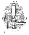
- the improved transmission apparatus of the present invention includes a motor output shaft 12 -having mounted at the distal end 13 thereof a beveled gear 14.
- Output shaft 12 is mounted in a first housing portion 16 and journaled for rotation by means of bearings 18 and 20.
- Motor shaft beveled gear 14 matingly engages transmission spindle shaft beveled gear 22, which is fixedly mounted on the transmission spindle shaft 24.
- Transmission spindle shaft 24 is mounted on housing 16 and journaled for rotation therein by means of bearings 26, 27.
- motor output shaft 12 may be disposed perpendicularly to transmission spindle shaft 24. In other embodiments, motor output shaft 12 may be disposed in- line disposition with transmission spindle shaft 24.
- the distal end 25 of transmission spindle shaft 24 has an eccentric 26 fixedly mounted thereon for eccentric rotation thereby.
- Eccentric 26 is rotationally mounted in a circular gear 28 by means of bearings 30, 32.
- Circular gear 28 is operatively connected to transmit the rotational motion of transmission spindle shaft 24 through and by means of eccentric 26.
- Circular gear 28 has first and second sets of external gear teeth 34, 36.
- An annulus gear 38 having internal gear teeth 40 is fixedly mounted with respect to circular gear 28 by fixed attachment between first housing portion 16 and second housing portion 41, which portions are secured by housing connecting bolts 43.
- Eccentric 26 is fixedly mounted on transmission spindle shaft 24 and freely mounted thereon for rotation thereabout is circular gear 28 for maintaining circular gear 28 and annulus gear 38 in overlapping relationship, for engaging their respective gear teeth, namely the first set of external gear teeth 34 of circular gear 28 and internal gear teeth 40 of fixedly disposed annulus gear 38, for rotation of circular gear 28 under the influence of annulus gear 38 in a second radial direction which is opposite to the first radial direction of the transmission spindle shaft 24.
- a rotatable drive hub 42 having internally disposed gear teeth 44 is disposed to surround a distal portion of circular gear 28, with internal gear teeth 44 of drive hub 42 engaging the second set of external gear teeth 36 of circular gear 28 to provide overlap between circular gear 28 and drive hub 42.
- rotational output shaft 46 Connected to drive hub 42 is rotational output shaft 46 which is journaled for rotation by bearings 48, 50 within second housing portion 41.
- An output wheel 52 is fixedly attached to output shaft 46 by means of a wheel hub bolt 53.
- the housing is preferably sealed and may be filled with a lubricant.
- a diaphragm 54 is sealingly disposed on housing 41 adjacent to wheel hub bolt 53 to form a sealed chamber 56 for controlling the pressure and volume of the interior of the housing.
- housing 41 for the improved transmission apparatus 10 of the present invention is shown with housing connecting bolts 43 for holding together the two portions 16, 41 of the housing, as described hereinabove.
- Housing connecting bolts 43 likewise serve to fixedly dispose annulus gear 38 with respect to the housing.
- Annulus gear 38 includes a designated number of internal gear teeth 40, the embodiment shown in Fig. 2 having twenty-six (26) such internal gear teeth 40.
- Disposed inside annulus gear 38 is circular gear 28, Fig. 2 showing the portion of circular gear 28 containing the first set 34 of external gear teeth.
- the embodiment depicted in Fig. 2 has twenty-five (25) such external gear teeth in the first set 34 thereof.
- circular gear 28 Lightness in weight of circular gear 28 may be enhanced by webbed construction, which includes a plurality of radially disposed spokes 58 connecting an inner portion 60 with an outer portion 62 thereof.
- Circular gear 28 includes a central aperture 64 therein, which contains eccentric 26 freely mounted for rotation of circular gear 28 thereabout by means of bearings 30. Shown in dotted lines are the proximal 23 and distal 25 portions of transmission spindle shaft 24 to emphasize that eccentric 26 is disposed off-center with respect to fixedly disposed annulus gear 38.
- eccentric 26 is rotated in a path eccentric to annulus center point C, thereby to cause the first set 34 of external gear teeth of circular gear 28 to overlap internal gear teeth 40 of annulus gear 38, to define thereby a point of maximum overlap P i .
- eccentric 26 rotates, with eccentric center point E revolving planetarily about annulus center point C the first set of external gear teeth 34 of circular gear 28 is forced into engagement with internal gear teeth 40 of fixedly disposed annulus gear 38.
- eccentric 26 is mounted for free rotation by means of the circumferentially disposed bearings 30, the engagement between the respective gear teeth causes rotation of circular gear 28 in the opposite direction, as depicted by Arrow B.
- a hypocycloid is traced at reduced rotational speed within annulus gear 38 by circular gear 28.
- the respective gear teeth 34a, 40a are in disengaged disposition, at the point of maximum overlap P 1 between first set 34 of external gear teeth of circular gear 28 and internal gear teeth 40 of fixedly disposed annulus gear 38, but are in engaged disposition at a distance therefrom of greater than 0°, but less than 90° as measured in the second direction, as indicated by Arrow B.
- the length of the engagement between the first set 34 of gear teeth of circular gear 28 and internal gear teeth 40 of annulus gear 38 is greatest near the point of maximum overlap P 1 between circular and annulus gears 28,38.
- teeth 34b, 40b have the longest such engagement, with the length of the engagement respectively diminishing for gear teeth 34c, 40c, 34d, 40d and 34e, 40e, disposed at increasing distances from the point of maximum overlap P 1 .
- the result is that the respective gear teeth of the first set of gear teeth of circular gear 28 and internal gear teeth 40 of annulus gear 38 first come under load while at maximum engagement, as shown in Figs. 2 and 4, and tip loading is prevented, which decreases the frictional loss of improved transmission apparatus 10 and prevents tip damage.
- rotatable drive hub 42 having internally disposed gear teeth 44 is disposed within housing second portion 41 of improved transmission apparatus 10.
- Internal gear teeth 44 of drive hub 42 engage the second set 36 of external gear teeth of circular gear 28 upon overlap between circular gear 28 and drive hub 42. The overlap therebetween is as is discussed hereinabove in regard to Fig. 2.
- the teeth of the second set 36 of external gear teeth of circular gear 28 are twenty-five (25) in number, which corresponds to the twenty-five (25) internal gear teeth 44 of rotatable drive hub 42.
- Second set 36 of external gear teeth of circular gear 28 and internal teeth 44 of drive hub 42 are in disengaged disposition at the point of maximum overlap P 2 , and in engaged disposition at a distance of greater than 0° but less than 90° as measured in the first direction, as shown by Arrow A.
- the length of the engagement between second set 36 of gear teeth of circular gear 28 and internal gear teeth 44 of drive hub 42 is greatest nearest the point of maximum overlap P 2 , and the length of the engagement diminishes for gear teeth disposed at increasing distance from the point of maximum overlap P 2 .
- the respective gear teeth 36, 44 first come under load while at a maximum engagement and tip loading is prevented thereby to decreased frictional loss and tip damage.
- An alternative embodiment of the improved transmission apparatus of the present invention is similar to the embodiment of Figs. 2-4, except for the number of gear teeth present in the second set of external gear teeth of the circular gear.
- the gear teeth of such second set of external gear teeth are preferably shaped similarly to those of the first set of external gear teeth.
- the difference between the number of gear teeth must be the same as the difference between the second set of gear teeth of the circular gear and those of the drive hub.
- the annulus gear has 26 gear teeth and the first set of external gear teeth of the circular gear has 25 gear teeth; and the drive hub has 25 gear teeth with the second set of external gear teeth having 24 gear teeth.
- the embodiment of the improved transmission apparatus of the present invention as shown in Figs. 2-4 attains a gear ratio reduction of -25:1, and the "two stage" reduction gear of the embodiment of Fig. 5 attains a gear ratio of +625 to 1.
- the method of operation of the alternative preferred embodiment as shown in Fig. 5 is somewhat different from the embodiments depicted hereinabove.
- the rotational output is the same rotational direction as the rotational input, rather than in the reverse rotational direction as in the embodiment of Figs. 2-4.
- the first set of external gear teeth of the circular gear are in engaged disposition with respect to the annulus gear at a distance of greater than 0° but less than 90° as measured in the first direction, rather than in the second direction, as shown in the embodiment of Figs. 2-4.
- the second set of external gear teeth is in engaged disposition with respect to the drive hub at a distance of greater than 0° but less than 90° from the point of maximum overlap as measured in the second direction.
- the length of such engagements in the alternative preferred embodiment of Fig. 5 are least nearest the point of maximum overlap between the circular gear teeth and respectively the annulus gear or drive hub, and the length of such engagement increases for gear teeth disposed at increasing distances from the point of maximum overlap.
- rotatable drive hub 142 having internally disposed gear teeth 144 is disposed within housing portion 141 of improved transmission apparatus 110.
- Internal gear teeth 144 of drive hub 142 engage the second set 136 of external gear teeth of the circular gear 128 upon overlap between circular gear 128 and drive hub 142. The overlap therebetween is similar to that depicted in Figs. 2-4.
- the number of gear teeth in the second set 136 of external gear teeth of the circular gear 128 is 24 in number, whereas the number of gear teeth 144 in rotatable drive hub 142 is 25 in number.
- the gear reduction ratio attained by the "second stage" of Fig. 5 is 25 to 1.
- Multiplied by the 25 to 1 gear reduction of the "first stage” the resulting gear reduction for the entire apparatus is 625 to 1.
- the overlap between the second set 136 of external gear teeth of circular gear 128 and internal teeth 144 of drive hub 142 defines a point of maximum overlap therebetween P 3 .
- the second set 136 of external gear teeth of circular gear 128 and internal teeth 144 of drive hub 142 are in disengaged disposition at the point of maximum overlap P 3 , and in engaged disposition at a distance of greater than 0° but less than 90° as measured in the second direction, as shown by Arrow B'.
- the point of engagement is in the opposite side of the point of maximum overlap P 3 from that of the embodiment depicted in Figs. 2-4.
- the length of the engagement between the second set 136 of gear teeth of circular gear 128 and internal gear teeth 144 of drive hub 142 is least nearest the point of maximum overlap P 3 , and the length of the engagement increases for gear teeth disposed at increasing radial distances from the point of maximum overlap P 3 .
- the respective gear teeth 136, 144 first come under load while at a minimal engagement.
- the point of such engagement is sufficiently far removed in distance from the tip of the gear to avoid tip loading and thus damage to such gear tips.
- lightness in weight of circular gear 128 is preferably enhanced by a webbed construction, which includes a plurality of radially disposed spokes 158 connecting an inner portion 160 with an outer portion 162 thereof.
- the various gears in the improved hypocyclic transmission apparatus of the present invention may be made of any material of sufficient strength and durability, and non-machined materials are preferred: examples are forged, cast, molded or extruded metal, plastic, or other relatively rigid and durable materials.
Landscapes
- Engineering & Computer Science (AREA)
- General Engineering & Computer Science (AREA)
- Mechanical Engineering (AREA)
- Chemical & Material Sciences (AREA)
- Combustion & Propulsion (AREA)
- Transportation (AREA)
- Retarders (AREA)
- Gear Transmission (AREA)
Claims (9)
Priority Applications (3)
| Application Number | Priority Date | Filing Date | Title |
|---|---|---|---|
| DE8282305863T DE3278437D1 (en) | 1982-11-04 | 1982-11-04 | Improved hypocyclic drive transmission apparatus |
| EP82305863A EP0108841B1 (fr) | 1982-11-04 | 1982-11-04 | Transmission à entraînement hypocycloidal |
| AT82305863T ATE34029T1 (de) | 1982-11-04 | 1982-11-04 | Getriebe mit hypozykloidalem antrieb. |
Applications Claiming Priority (1)
| Application Number | Priority Date | Filing Date | Title |
|---|---|---|---|
| EP82305863A EP0108841B1 (fr) | 1982-11-04 | 1982-11-04 | Transmission à entraînement hypocycloidal |
Publications (2)
| Publication Number | Publication Date |
|---|---|
| EP0108841A1 EP0108841A1 (fr) | 1984-05-23 |
| EP0108841B1 true EP0108841B1 (fr) | 1988-05-04 |
Family
ID=8189824
Family Applications (1)
| Application Number | Title | Priority Date | Filing Date |
|---|---|---|---|
| EP82305863A Expired EP0108841B1 (fr) | 1982-11-04 | 1982-11-04 | Transmission à entraînement hypocycloidal |
Country Status (3)
| Country | Link |
|---|---|
| EP (1) | EP0108841B1 (fr) |
| AT (1) | ATE34029T1 (fr) |
| DE (1) | DE3278437D1 (fr) |
Cited By (1)
| Publication number | Priority date | Publication date | Assignee | Title |
|---|---|---|---|---|
| WO2017210265A1 (fr) * | 2016-06-01 | 2017-12-07 | SunDrive Technologies, LLC | Boîte de vitesses à double fonction, système de boîte de vitesses et procédé |
Families Citing this family (6)
| Publication number | Priority date | Publication date | Assignee | Title |
|---|---|---|---|---|
| EP0233303B1 (fr) * | 1986-02-19 | 1990-10-17 | Sumitomo Heavy Industries, Ltd | Engrenage planétaire |
| SE525626C2 (sv) * | 2003-03-05 | 2005-03-22 | Volvo Constr Equip Holding Se | Anordning för drivning av ett hjul hos ett fordon |
| GB0412723D0 (en) * | 2004-06-08 | 2004-07-07 | Newton Alan R | Offset drive direct ratio gear coupling |
| EP1743796A3 (fr) * | 2005-07-13 | 2007-03-28 | Kanzaki Kokyukoki MFG. Co., Ltd. | Mécanisme d'entraînement de roue |
| US8319950B2 (en) | 2009-10-19 | 2012-11-27 | Trimble Navigation Limited | Multiple-wavelength capable laser receiver |
| US9927005B2 (en) | 2015-08-10 | 2018-03-27 | Southwest Research Institute | Two-stage hypocycloidal gear train |
Citations (1)
| Publication number | Priority date | Publication date | Assignee | Title |
|---|---|---|---|---|
| US4306540A (en) * | 1979-06-25 | 1981-12-22 | Solar Kinetics, Inc. | Solar collector mounting and support apparatus |
Family Cites Families (7)
| Publication number | Priority date | Publication date | Assignee | Title |
|---|---|---|---|---|
| DE359167C (de) * | 1919-11-18 | 1922-09-21 | Petermann & Co | Umlaufraedergetriebe |
| US2250259A (en) * | 1940-03-11 | 1941-07-22 | Jr Bradford Foote | Speed reducing gearing |
| GB1101522A (en) * | 1966-03-28 | 1968-01-31 | Rolls Royce | Improvements relating to gearing |
| JPS5025100B1 (fr) * | 1968-10-12 | 1975-08-21 | ||
| DE2007853A1 (de) * | 1970-02-20 | 1971-08-26 | Zahnradfabrik Friedrichshafen | Verzahnung fur Innengetriebe |
| US4014224A (en) * | 1973-10-12 | 1977-03-29 | Pitts Drive, Inc. | Speed differential planetary gear train |
| US4023441A (en) * | 1974-11-15 | 1977-05-17 | Osterwalder Jean Pierre F | Speed reducing device |
-
1982
- 1982-11-04 DE DE8282305863T patent/DE3278437D1/de not_active Expired
- 1982-11-04 AT AT82305863T patent/ATE34029T1/de not_active IP Right Cessation
- 1982-11-04 EP EP82305863A patent/EP0108841B1/fr not_active Expired
Patent Citations (1)
| Publication number | Priority date | Publication date | Assignee | Title |
|---|---|---|---|---|
| US4306540A (en) * | 1979-06-25 | 1981-12-22 | Solar Kinetics, Inc. | Solar collector mounting and support apparatus |
Cited By (1)
| Publication number | Priority date | Publication date | Assignee | Title |
|---|---|---|---|---|
| WO2017210265A1 (fr) * | 2016-06-01 | 2017-12-07 | SunDrive Technologies, LLC | Boîte de vitesses à double fonction, système de boîte de vitesses et procédé |
Also Published As
| Publication number | Publication date |
|---|---|
| DE3278437D1 (en) | 1988-06-09 |
| EP0108841A1 (fr) | 1984-05-23 |
| ATE34029T1 (de) | 1988-05-15 |
Similar Documents
| Publication | Publication Date | Title |
|---|---|---|
| US6652408B2 (en) | Vehicular differential with ring gear directly loading the differential pin | |
| EP0305535A1 (fr) | Reducteur epicycloidal | |
| US4386540A (en) | Hypocyclic drive transmission apparatus | |
| EP0108841B1 (fr) | Transmission à entraînement hypocycloidal | |
| EP0058834B1 (fr) | Transmission à variation continue pour véhicules automobiles | |
| US4909100A (en) | Differential gear device incorporating internal meshing type planetary reduction gear | |
| EP0233303B1 (fr) | Engrenage planétaire | |
| EP1627158B1 (fr) | Systeme de commande d'engrenages repartissant le couple et procede pour commander un engrenage de sortie | |
| US20020119856A1 (en) | Hydromechanical transmission | |
| US6338689B1 (en) | Hydromechanical transmission | |
| GB2354563A (en) | Lockable differential | |
| GB2187824A (en) | Fluid coupling transmission | |
| EP0227547A3 (fr) | Transmission hydraulique | |
| CN212584194U (zh) | 同轴正反转双输出减速机 | |
| US6523430B1 (en) | Power take-off unit with gearset | |
| EP0216540A1 (fr) | Transmission de puissance pour mouvement de rotation | |
| US4128022A (en) | Rotatable shaft coupling | |
| US5910065A (en) | Transmission with creep gear | |
| US5431606A (en) | Ball worm gear final rear axle differential drive | |
| JPH09280323A (ja) | ホイールモータ | |
| EP1527933A2 (fr) | Système de transmission de puissance à différentiel pour véhicule | |
| US12584540B2 (en) | Gear reduction unit with anti-backlash mechanism | |
| RU2099614C1 (ru) | Прецессионная передача | |
| RU2162973C2 (ru) | Дифференциальный привод | |
| SU1318439A1 (ru) | Коробка передач транспортного средства |
Legal Events
| Date | Code | Title | Description |
|---|---|---|---|
| PUAI | Public reference made under article 153(3) epc to a published international application that has entered the european phase |
Free format text: ORIGINAL CODE: 0009012 |
|
| AK | Designated contracting states |
Designated state(s): AT BE CH DE FR GB IT LI LU NL SE |
|
| 17P | Request for examination filed |
Effective date: 19841107 |
|
| 17Q | First examination report despatched |
Effective date: 19860127 |
|
| GRAA | (expected) grant |
Free format text: ORIGINAL CODE: 0009210 |
|
| AK | Designated contracting states |
Kind code of ref document: B1 Designated state(s): AT BE CH DE FR GB IT LI LU NL SE |
|
| PG25 | Lapsed in a contracting state [announced via postgrant information from national office to epo] |
Ref country code: NL Effective date: 19880504 Ref country code: LI Effective date: 19880504 Ref country code: CH Effective date: 19880504 Ref country code: AT Effective date: 19880504 |
|
| REF | Corresponds to: |
Ref document number: 34029 Country of ref document: AT Date of ref document: 19880515 Kind code of ref document: T |
|
| PG25 | Lapsed in a contracting state [announced via postgrant information from national office to epo] |
Ref country code: SE Effective date: 19880531 |
|
| REF | Corresponds to: |
Ref document number: 3278437 Country of ref document: DE Date of ref document: 19880609 |
|
| ITF | It: translation for a ep patent filed | ||
| ET | Fr: translation filed | ||
| REG | Reference to a national code |
Ref country code: CH Ref legal event code: PL |
|
| NLV1 | Nl: lapsed or annulled due to failure to fulfill the requirements of art. 29p and 29m of the patents act | ||
| PG25 | Lapsed in a contracting state [announced via postgrant information from national office to epo] |
Ref country code: LU Free format text: LAPSE BECAUSE OF NON-PAYMENT OF DUE FEES Effective date: 19881130 |
|
| PLBE | No opposition filed within time limit |
Free format text: ORIGINAL CODE: 0009261 |
|
| STAA | Information on the status of an ep patent application or granted ep patent |
Free format text: STATUS: NO OPPOSITION FILED WITHIN TIME LIMIT |
|
| 26N | No opposition filed | ||
| PGFP | Annual fee paid to national office [announced via postgrant information from national office to epo] |
Ref country code: BE Payment date: 19891117 Year of fee payment: 8 |
|
| PGFP | Annual fee paid to national office [announced via postgrant information from national office to epo] |
Ref country code: LU Payment date: 19891211 Year of fee payment: 8 |
|
| PG25 | Lapsed in a contracting state [announced via postgrant information from national office to epo] |
Ref country code: BE Effective date: 19901130 |
|
| BERE | Be: lapsed |
Owner name: CURTIS LLOYD STUART Effective date: 19901130 |
|
| PGFP | Annual fee paid to national office [announced via postgrant information from national office to epo] |
Ref country code: GB Payment date: 19921009 Year of fee payment: 11 |
|
| PGFP | Annual fee paid to national office [announced via postgrant information from national office to epo] |
Ref country code: FR Payment date: 19921111 Year of fee payment: 11 |
|
| ITTA | It: last paid annual fee | ||
| PGFP | Annual fee paid to national office [announced via postgrant information from national office to epo] |
Ref country code: DE Payment date: 19921130 Year of fee payment: 11 |
|
| PG25 | Lapsed in a contracting state [announced via postgrant information from national office to epo] |
Ref country code: GB Effective date: 19931104 |
|
| GBPC | Gb: european patent ceased through non-payment of renewal fee |
Effective date: 19931104 |
|
| PG25 | Lapsed in a contracting state [announced via postgrant information from national office to epo] |
Ref country code: FR Effective date: 19940729 |
|
| PG25 | Lapsed in a contracting state [announced via postgrant information from national office to epo] |
Ref country code: DE Effective date: 19940802 |
|
| REG | Reference to a national code |
Ref country code: FR Ref legal event code: ST |