EP0108907A1 - Assemblage combustible pour réacteur nucléaire avec grille de maintien des barres facilement enlevable - Google Patents
Assemblage combustible pour réacteur nucléaire avec grille de maintien des barres facilement enlevable Download PDFInfo
- Publication number
- EP0108907A1 EP0108907A1 EP83109865A EP83109865A EP0108907A1 EP 0108907 A1 EP0108907 A1 EP 0108907A1 EP 83109865 A EP83109865 A EP 83109865A EP 83109865 A EP83109865 A EP 83109865A EP 0108907 A1 EP0108907 A1 EP 0108907A1
- Authority
- EP
- European Patent Office
- Prior art keywords
- fuel
- rod holding
- rod
- rods
- fuel rods
- Prior art date
- Legal status (The legal status is an assumption and is not a legal conclusion. Google has not performed a legal analysis and makes no representation as to the accuracy of the status listed.)
- Granted
Links
- 239000003758 nuclear fuel Substances 0.000 title claims abstract description 5
- 239000000446 fuel Substances 0.000 claims abstract description 59
- 239000002826 coolant Substances 0.000 claims abstract description 6
- 238000000605 extraction Methods 0.000 abstract 1
- 230000000717 retained effect Effects 0.000 abstract 1
- 125000006850 spacer group Chemical group 0.000 description 4
- 230000005855 radiation Effects 0.000 description 3
- 230000000712 assembly Effects 0.000 description 2
- 238000000429 assembly Methods 0.000 description 2
- 238000005253 cladding Methods 0.000 description 2
- 238000010276 construction Methods 0.000 description 2
- 230000002950 deficient Effects 0.000 description 2
- 230000007547 defect Effects 0.000 description 1
- 230000002349 favourable effect Effects 0.000 description 1
- 239000012530 fluid Substances 0.000 description 1
- 238000003780 insertion Methods 0.000 description 1
- 230000037431 insertion Effects 0.000 description 1
- 238000012958 reprocessing Methods 0.000 description 1
- 238000000926 separation method Methods 0.000 description 1
- 230000008961 swelling Effects 0.000 description 1
Images


Classifications
-
- G—PHYSICS
- G21—NUCLEAR PHYSICS; NUCLEAR ENGINEERING
- G21C—NUCLEAR REACTORS
- G21C3/00—Reactor fuel elements and their assemblies; Selection of substances for use as reactor fuel elements
- G21C3/30—Assemblies of a number of fuel elements in the form of a rigid unit
- G21C3/32—Bundles of parallel pin-, rod-, or tube-shaped fuel elements
- G21C3/33—Supporting or hanging of elements in the bundle; Means forming part of the bundle for inserting it into, or removing it from, the core; Means for coupling adjacent bundles
- G21C3/3305—Lower nozzle
-
- G—PHYSICS
- G21—NUCLEAR PHYSICS; NUCLEAR ENGINEERING
- G21C—NUCLEAR REACTORS
- G21C3/00—Reactor fuel elements and their assemblies; Selection of substances for use as reactor fuel elements
- G21C3/30—Assemblies of a number of fuel elements in the form of a rigid unit
- G21C3/32—Bundles of parallel pin-, rod-, or tube-shaped fuel elements
- G21C3/33—Supporting or hanging of elements in the bundle; Means forming part of the bundle for inserting it into, or removing it from, the core; Means for coupling adjacent bundles
-
- Y—GENERAL TAGGING OF NEW TECHNOLOGICAL DEVELOPMENTS; GENERAL TAGGING OF CROSS-SECTIONAL TECHNOLOGIES SPANNING OVER SEVERAL SECTIONS OF THE IPC; TECHNICAL SUBJECTS COVERED BY FORMER USPC CROSS-REFERENCE ART COLLECTIONS [XRACs] AND DIGESTS
- Y02—TECHNOLOGIES OR APPLICATIONS FOR MITIGATION OR ADAPTATION AGAINST CLIMATE CHANGE
- Y02E—REDUCTION OF GREENHOUSE GAS [GHG] EMISSIONS, RELATED TO ENERGY GENERATION, TRANSMISSION OR DISTRIBUTION
- Y02E30/00—Energy generation of nuclear origin
- Y02E30/30—Nuclear fission reactors
Definitions
- the present invention relates to a nuclear reactor fuel element according to the preamble of the first claim.
- fuel assemblies are known in a variety of embodiments. What they have in common is that the fuel rods are held against the coolant flow which is usually directed upwards through the element in a rod holding plate arranged near the lower end of the element. The individual fuel rods are often screwed into the rod holding plate or fastened by plastic deformation of the rod end. Such connections cannot be detached again during the dismantling of the fuel elements prior to the reprocessing of the fuel or can only be detached again with difficulty using remote-controlled tools.
- the object of the present invention is a nuclear reactor fuel element which, through the design of the fastening of the fuel rods in the rod holding plate, permits both the replacement of a single fuel rod and also allows the element to be dismantled easily and with little effort and with as little use of cutting tools as possible.
- the rod holding plates offer favorable points of attack for the gripping tools used for pulling, whereby the number of sub-bundles and thus the number of rods in each of them can be selected so that only such a force is used to pull the fuel rods (deformed under the influence of neutron radiation) which does not endanger the integrity of the long and very thin-walled fuel rods. Because each fuel rod can be removed and re-installed individually, there is the possibility of repairing a fuel element in which one of the several hundred fuel rods has become defective with relatively little effort.
- the third claim defines an embodiment of this The idea of the invention, in which the removal of the element base is sufficient to be able to simply pull the rod holding plates out of the envelope box. No further operations, such as with cutting tools, are required.
- the dimensioning of the openings in the rod holding plates ensures that the fuel rods are fixed in the longitudinal dimension of the element and, on the other hand, allows a single fuel rod to be easily pulled out of the bundle and the later insertion of a replacement rod.
- the diameter of the openings in the rod holding plate is to be selected somewhat larger than that of the fuel rods even in the unirradiated state, in order later to allow the rod swollen by neutron radiation, in particular in its central region, to pass easily.
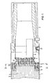
- the fuel assembly consists of a hexagonal casing 1 in the example, which is connected at its lower end by means of pins 21 to a tapering foot 2, with the latter Help the element is fixed in a corresponding opening in a core support plate, not shown here.
- the coolant flows upward through the opening in the foot 2 and dissipates the heat generated in fuel rods 3, 4.
- the fuel rods 3 are combined into an outer bundle and the fuel rods 4 into an inner bundle, which are arranged concentrically to one another.
- the fuel rods 3, 4 are flattened at their ends and provided with ends 31, 41 which are thickened compared to the remaining diameter. Stops 11 are welded onto the inside of the envelope box 1, which limit the path of an upper rod holding plate 5 which is loosely inserted into the envelope box 1.
- a lower rod holding plate 6 which extends over the entire cross section thereof and which is likewise provided with openings for the passage of the coolant.
- these openings are smaller than the thickened fuel rod ends 31, which are thus held in the other direction and on the other hand act as spacers between the upper 5 and lower rod holding plate 6.
- the openings are smaller than the thickened fuel rod ends 41, so that these are also fixed in one direction.
- the openings in the rod holding plates 5, 6 are dimensioned such that the fuel rods 3, 4 can be pushed through until their thickened ends 31, 41 stop.
- the fixation of the fuel rods 4 of the inner rod bundle in the other direction is carried out by a counter plate 7 which is firmly connected to the fuel element base 2 via supports 8.
- the openings in it are smaller than the thickened fuel rod ends 41, so that the counter plate secures the fuel rods 4 of the inner bundle in the other direction.
- the thickened fuel rod ends 41 act as spacers between the lower rod holding plate 6 and the counter plate 7.
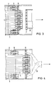
- the fuel element base 2 has been separated from the casing 1 by a saw cut (if the fuel contained in the element is to be reprocessed), or the pins 21 have been loosened in the event of a repair, and the former can be removed together with the counterplate 7 in the direction indicated by the arrow.
- Individual fuel rods 4 of the inner bundle can then be pulled out of the bundle at their thickened ends 41 by a suitable pliers-like gripping tool (not shown here). Since the openings in the rod holding plates 5, 6 are larger than the diameter of the fuel rods 3, 4 in the unirradiated state, it is also possible to pull out such rods without the use of greater forces, which increases their diameter due to the neutron radiation due to swelling over part of their length to have.
- a new fuel rod 4 for a pulled out due to a defect can be inserted into the lower rod holding plate 6 without difficulty.
- the fuel assembly base can then be connected to the casing 1 again by means of the pins 21, as a result of which the counterplate 7 is brought back into its position holding the fuel rods 4.
- the gripper 9 can also engage in corresponding undercuts in the upper rod holding plate 5 and pull the outer bundle of rods as a whole.
- the forces to be expended are only about half of the several hundred fuel rods at a time drawn from the spacers, not shown here, which are arranged further up in the cladding tube, and must also be much less and certainly within the for the strength of the thin-walled fuel rods and Spacers allowable values.
- Fig. 6 shows an embodiment for a fuel assembly, in which (e.g. due to a smaller number of fuel rods 3) the division of the rod holding plate 5 can be dispensed with. In order to be able to pull it easily, it is provided with extensions 51 which protrude through any undercuts, such as e.g. Have holes in which the gripper 9 can grip.
Landscapes
- Physics & Mathematics (AREA)
- Engineering & Computer Science (AREA)
- Plasma & Fusion (AREA)
- General Engineering & Computer Science (AREA)
- High Energy & Nuclear Physics (AREA)
- Monitoring And Testing Of Nuclear Reactors (AREA)
Applications Claiming Priority (2)
| Application Number | Priority Date | Filing Date | Title |
|---|---|---|---|
| DE19823238297 DE3238297A1 (de) | 1982-10-15 | 1982-10-15 | Kernreaktorbrennelement mit leicht ziehbarer stabhalteplatte |
| DE3238297 | 1982-10-15 |
Publications (2)
| Publication Number | Publication Date |
|---|---|
| EP0108907A1 true EP0108907A1 (fr) | 1984-05-23 |
| EP0108907B1 EP0108907B1 (fr) | 1987-08-19 |
Family
ID=6175832
Family Applications (1)
| Application Number | Title | Priority Date | Filing Date |
|---|---|---|---|
| EP83109865A Expired EP0108907B1 (fr) | 1982-10-15 | 1983-10-03 | Assemblage combustible pour réacteur nucléaire avec grille de maintien des barres facilement enlevable |
Country Status (2)
| Country | Link |
|---|---|
| EP (1) | EP0108907B1 (fr) |
| DE (2) | DE3238297A1 (fr) |
Cited By (2)
| Publication number | Priority date | Publication date | Assignee | Title |
|---|---|---|---|---|
| WO1992011640A1 (fr) * | 1990-12-21 | 1992-07-09 | Siemens Aktiengesellschaft | Element combustible de reacteur nucleaire |
| CN113128714A (zh) * | 2021-04-20 | 2021-07-16 | 广东核电合营有限公司 | 一种基于核电机组控制棒的试验系统及核对试验方法 |
Families Citing this family (2)
| Publication number | Priority date | Publication date | Assignee | Title |
|---|---|---|---|---|
| US4988473A (en) * | 1988-12-08 | 1991-01-29 | Westinghouse Electric Corp. | Self-latching reactivity-reducing device for use in on-site spent fuel assembly storage |
| US4917856A (en) * | 1988-12-08 | 1990-04-17 | Westinghouse Electric Corp. | Self-latching reactivity-reducing device for use in on-site spent fuel assembly storage |
Citations (10)
| Publication number | Priority date | Publication date | Assignee | Title |
|---|---|---|---|---|
| US3389056A (en) * | 1964-07-09 | 1968-06-18 | Westinghouse Electric Corp | Fuel assemblies |
| DE1439936A1 (de) * | 1961-12-01 | 1969-09-25 | Westinghouse Electric Corp | Brennelement fuer heterogene Atomreaktoren |
| US3481021A (en) * | 1965-05-24 | 1969-12-02 | Asea Ab | Method of manufacturing fuel assemblies |
| FR2195824A1 (fr) * | 1972-08-11 | 1974-03-08 | Asea Atom Ab | |
| US3917335A (en) * | 1971-09-07 | 1975-11-04 | Transfer Systems | Fuel assemblies, grapples therefor and fuel transport apparatus for nuclear reactor power plant |
| GB1478985A (en) * | 1975-03-24 | 1977-07-06 | Atomic Energy Authority Uk | Nuclear reactor fuel element sub-assemblies |
| DE2721869A1 (de) * | 1977-05-14 | 1978-11-23 | Interatom | Stabhalterung fuer kernreaktor- brennelement |
| FR2426311A1 (fr) * | 1978-05-18 | 1979-12-14 | Atomic Energy Authority Uk | Sous-assemblage combustible, notamment pour surregenerateur a neutrons rapides, et son procede de degainage |
| DE3150477A1 (de) * | 1980-12-30 | 1982-08-26 | Aktiebolaget Asea-Atom, 72183 Västerås | Brennstabbuendel |
| EP0065238A2 (fr) * | 1981-05-15 | 1982-11-24 | Ab Asea-Atom | Assemblage combustible pour un réacteur nucléaire à liquide bouillant |
-
1982
- 1982-10-15 DE DE19823238297 patent/DE3238297A1/de not_active Withdrawn
-
1983
- 1983-10-03 EP EP83109865A patent/EP0108907B1/fr not_active Expired
- 1983-10-03 DE DE8383109865T patent/DE3373158D1/de not_active Expired
Patent Citations (10)
| Publication number | Priority date | Publication date | Assignee | Title |
|---|---|---|---|---|
| DE1439936A1 (de) * | 1961-12-01 | 1969-09-25 | Westinghouse Electric Corp | Brennelement fuer heterogene Atomreaktoren |
| US3389056A (en) * | 1964-07-09 | 1968-06-18 | Westinghouse Electric Corp | Fuel assemblies |
| US3481021A (en) * | 1965-05-24 | 1969-12-02 | Asea Ab | Method of manufacturing fuel assemblies |
| US3917335A (en) * | 1971-09-07 | 1975-11-04 | Transfer Systems | Fuel assemblies, grapples therefor and fuel transport apparatus for nuclear reactor power plant |
| FR2195824A1 (fr) * | 1972-08-11 | 1974-03-08 | Asea Atom Ab | |
| GB1478985A (en) * | 1975-03-24 | 1977-07-06 | Atomic Energy Authority Uk | Nuclear reactor fuel element sub-assemblies |
| DE2721869A1 (de) * | 1977-05-14 | 1978-11-23 | Interatom | Stabhalterung fuer kernreaktor- brennelement |
| FR2426311A1 (fr) * | 1978-05-18 | 1979-12-14 | Atomic Energy Authority Uk | Sous-assemblage combustible, notamment pour surregenerateur a neutrons rapides, et son procede de degainage |
| DE3150477A1 (de) * | 1980-12-30 | 1982-08-26 | Aktiebolaget Asea-Atom, 72183 Västerås | Brennstabbuendel |
| EP0065238A2 (fr) * | 1981-05-15 | 1982-11-24 | Ab Asea-Atom | Assemblage combustible pour un réacteur nucléaire à liquide bouillant |
Non-Patent Citations (1)
| Title |
|---|
| PATENTS ABSTRACTS OF JAPAN, Band 3, Nr. 154 (M-85), 18. Dezember 1979, Seiten 34 M 85 & JP - A - 54 130 789 (TOKYO SHIBAURA DENKI K.K.) 11.10.1979 * |
Cited By (2)
| Publication number | Priority date | Publication date | Assignee | Title |
|---|---|---|---|---|
| WO1992011640A1 (fr) * | 1990-12-21 | 1992-07-09 | Siemens Aktiengesellschaft | Element combustible de reacteur nucleaire |
| CN113128714A (zh) * | 2021-04-20 | 2021-07-16 | 广东核电合营有限公司 | 一种基于核电机组控制棒的试验系统及核对试验方法 |
Also Published As
| Publication number | Publication date |
|---|---|
| EP0108907B1 (fr) | 1987-08-19 |
| DE3238297A1 (de) | 1984-04-19 |
| DE3373158D1 (en) | 1987-09-24 |
Similar Documents
| Publication | Publication Date | Title |
|---|---|---|
| EP0549639B1 (fr) | Element combustible pour reacteur a eau bouillante presentant un support compose d'elements standardises | |
| DE69409010T2 (de) | Zerlegbares brennstabbündel eines leichtwassergekühlten kernreaktors | |
| DE2517479A1 (de) | Vorrichtung zur entfernung von moeglicherweise schaedlichen fertigungsrueckstaenden o.dgl., wie beispielsweise metallspaene, waehrend der dem betrieb vorausgehenden pruefung aus einem kernreaktor | |
| DE2631182B2 (de) | Mutternplatte für ein Kernreaktor-Brennelement | |
| DE3202238C2 (fr) | ||
| EP0054827A1 (fr) | Elément combustible pour réacteurs nucléaires à eau bouillante | |
| DE2747132C3 (de) | Demontierbares Brennelement für Atomkernreaktor | |
| DE2435584A1 (de) | Anordnung der brennstoffstaebe in kernreaktoren | |
| DE69107752T2 (de) | Führungseinrichtung für das Kontrollbündel eines Kernreaktors. | |
| EP0108907B1 (fr) | Assemblage combustible pour réacteur nucléaire avec grille de maintien des barres facilement enlevable | |
| DE68915669T2 (de) | Zerlegbare Befestigungsvorrichtung eines Führungsrohres in einem Brennstabbündelendstück eines Kernreaktors. | |
| DE19641326A1 (de) | Brennelement ohne obere Gitterplatte für Siedewasserreaktor | |
| DE2817540A1 (de) | Deckenreflektor fuer einen gasgekuehlten kugelhaufenreaktor und verfahren zum ausbau des deckenreflektors | |
| DE2749583C3 (de) | Kernbrennelement mit einer Abstandshalteeinrichtung | |
| EP0252375B1 (fr) | Méthode pour réparer un assemblage de combustible nucléaire et crayon de remplacement utilisé pour la mise en oeuvre | |
| DE19536407A1 (de) | Kern eines Druckwasser-Kernreaktors und oberes Endstück einer Brennelementkassette des Kerns | |
| DE69404274T2 (de) | Anpassbares Halterungsmittel für existierende Wärmetauscher von der Art "Rohre-in-Mantel" | |
| DE69810151T2 (de) | Rahmenanordnung für plattenwärmetauscher | |
| EP0033074A2 (fr) | Installation de réparation d'éléments combustibles pour réacteurs nucléaires à eau bouillante | |
| DE69102259T2 (de) | Verfahren und Vorrichtung zur Reparatur eines Abstandhalters in einem Kernreaktorbrennstabbündel. | |
| DE8229002U1 (de) | Kernreaktorbrennelement mit leicht ziehbarer stabhalteplatte | |
| DE68906995T2 (de) | Zerlegbares brennstabbuendel fuer leichtwassergekuehlten kernreaktor. | |
| EP0512132B1 (fr) | Assemblage de combustible à eau pressurisée comprenant un emboul inférieur avec dispositif de retenue de debris | |
| DE68902127T2 (de) | Vorrichtung zum einsetzen einer extraktionshuelse in ein dampferzeugerrohr und verfahren zum herausziehen des entsprechenden rohrteilstueckes. | |
| DE3344738C2 (de) | Zerlegbares Brennelement für Kernreaktoren |
Legal Events
| Date | Code | Title | Description |
|---|---|---|---|
| PUAI | Public reference made under article 153(3) epc to a published international application that has entered the european phase |
Free format text: ORIGINAL CODE: 0009012 |
|
| AK | Designated contracting states |
Designated state(s): DE FR GB IT |
|
| 17P | Request for examination filed |
Effective date: 19841026 |
|
| RAP1 | Party data changed (applicant data changed or rights of an application transferred) |
Owner name: INTERATOM GESELLSCHAFT MIT BESCHRAENKTER HAFTUNG |
|
| 17Q | First examination report despatched |
Effective date: 19860317 |
|
| GRAA | (expected) grant |
Free format text: ORIGINAL CODE: 0009210 |
|
| AK | Designated contracting states |
Kind code of ref document: B1 Designated state(s): DE FR GB IT |
|
| REF | Corresponds to: |
Ref document number: 3373158 Country of ref document: DE Date of ref document: 19870924 |
|
| ET | Fr: translation filed | ||
| ITF | It: translation for a ep patent filed | ||
| PLBE | No opposition filed within time limit |
Free format text: ORIGINAL CODE: 0009261 |
|
| STAA | Information on the status of an ep patent application or granted ep patent |
Free format text: STATUS: NO OPPOSITION FILED WITHIN TIME LIMIT |
|
| 26N | No opposition filed | ||
| PG25 | Lapsed in a contracting state [announced via postgrant information from national office to epo] |
Ref country code: DE Effective date: 19890701 |
|
| PG25 | Lapsed in a contracting state [announced via postgrant information from national office to epo] |
Ref country code: GB Effective date: 19891003 |
|
| GBPC | Gb: european patent ceased through non-payment of renewal fee | ||
| PG25 | Lapsed in a contracting state [announced via postgrant information from national office to epo] |
Ref country code: FR Effective date: 19900629 |
|
| REG | Reference to a national code |
Ref country code: FR Ref legal event code: ST |