EP0108928A2 - Méthode de régulation d'une centrale de force motrice - Google Patents
Méthode de régulation d'une centrale de force motrice Download PDFInfo
- Publication number
- EP0108928A2 EP0108928A2 EP83110099A EP83110099A EP0108928A2 EP 0108928 A2 EP0108928 A2 EP 0108928A2 EP 83110099 A EP83110099 A EP 83110099A EP 83110099 A EP83110099 A EP 83110099A EP 0108928 A2 EP0108928 A2 EP 0108928A2
- Authority
- EP
- European Patent Office
- Prior art keywords
- setpoint
- steam
- steam generator
- input
- power
- Prior art date
- Legal status (The legal status is an assumption and is not a legal conclusion. Google has not performed a legal analysis and makes no representation as to the accuracy of the status listed.)
- Granted
Links
Images


Classifications
-
- F—MECHANICAL ENGINEERING; LIGHTING; HEATING; WEAPONS; BLASTING
- F01—MACHINES OR ENGINES IN GENERAL; ENGINE PLANTS IN GENERAL; STEAM ENGINES
- F01K—STEAM ENGINE PLANTS; STEAM ACCUMULATORS; ENGINE PLANTS NOT OTHERWISE PROVIDED FOR; ENGINES USING SPECIAL WORKING FLUIDS OR CYCLES
- F01K13/00—General layout or general methods of operation of complete plants
- F01K13/02—Controlling, e.g. stopping or starting
Definitions
- the invention relates to a method for controlling a power plant block containing a turbine and a steam generator, in which the basic setpoint for the block power is supplied to the steam generator as the basic setpoint for the steam generation and the turbine control as the basic setpoint for the electrical power.
- the opening of the turbine valve remains constant and only the steam generator is readjusted. Only in the event of sudden changes in the mains frequency is the turbine valve opening changed in this operating mode and thus the steam accumulator is used. In the lower and upper load range, so-called fixed pressure operation is used, ie the opening of the turbine inlet valve is changed with a constant steam pressure in order to change the power. So that the steam accumulator is not used, the setpoint for the valve opening is adjusted via a delay element with which the delay time of the steam generator is simulated. Since this measure only adjusts the valve opening when the steam generation changes, the steam pressure remains constant when the load changes. In this known method, the storage behavior of the steam generator is only considered incompletely. Also, no measures are proposed with which the valve opening is not changed in the event of a heating fault. An exact replication of the load-dependent time behavior of the steam generator is required for the regulation of frequency deviations.
- the present invention has for its object to provide a method of the type mentioned, in which the dynamic processes in power changes are taken into account more than in the known methods and thereby the control and regulation processes are better separated and in which the commissioning is also simplified .
- a first value corresponding to the opening of the turbine inlet valve is preferably formed and fed to the one input of a multiplier, the output signal of which is subtracted from the basic setpoint for the block power.
- the difference value is applied to the basic setpoint for the steam generator and fed to the input of an integrator emulating the storage behavior of the steam generator, to the output of which the second input of the multiplier is connected.
- a signal corresponding to the frequency deviation from the desired value is advantageously fed to the desired value for the electrical power, that is to say to control the turbine valve, and to the desired value for the steam generator.
- the signal corresponding to the frequency deviation can be used directly and via a delay time of the steamer
- the corresponding delay element can be guided to a subtraction stage, the output signal of which is applied to the setpoint for the steam generator.
- the electrical power is regulated using the turbine inlet valve and the steam pressure using the steam generator.
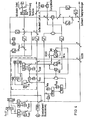
- the basic setpoint for the block output is set according to a schedule with an adjuster ST1 and passed on to the block control via a downstream setpoint control SWF.
- This basic setpoint for the block power is passed on without delay as a setpoint for the steam generation via a line SWD and via a delay element VZ1, the timing of which is the same as that of the steam generator, as a setpoint for the electrical power via a line SWL.
- the delay and start-up time of the steam generator is simulated in the delay element VZ1.
- This transition function is determined by suddenly changing the setpoint for the steam generator and the temporal value when the steam pressure is constantly controlled by the turbine Course of electrical power is recorded. Since the time behavior of the steam generator depends on the power, the transition function must be with several, for. B. three different, load points are included. According to these values, the time behavior of the delay elements designated VZ1, VZ2 ... is controlled by the setpoint for the block power.
- a unit 4 with a dashed outline serves to generate a signal which corresponds approximately to the valve opening.
- the pressure setpoint is performance-dependent within limit setpoints p min and p, which are set with adjusters ST4, ST5.
- a constant throttle reserve in the entire sliding pressure range, a constant value ⁇ p, which is set with an adjuster ST6, is added to the power setpoint in order to form the pressure setpoint in an adder ADD3.
- a minimum selection MIN3 is connected downstream of the adder ADD3 and the adjuster ST4, to which the one input of a maximum selection MAX3 is connected, to which the limit setpoint p min is also fed.
- At the output of the maximum selection MAX3 there is a basic setpoint for the steam pressure.
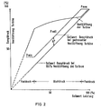
- the steam pressure changes with a delay in accordance with the storage capacity of the steam generator, the opening of the turbine valve and the time behavior of the steam generator. So that there is no control difference for a steam pressure regulator 6 due to a change in the basic setpoint for the block output even in the sliding pressure range (see FIG. 2), the setpoint for the steam pressure must also be delayed in accordance with the actual value.
- the power of the steam generator for loading or unloading the memory is thus overridden in terms of time and amount so that there is no difference between the delayed setpoint "power" and the electrical power.
- the opening of the turbine valve is changed only in the event of a control difference “steam pressure” via the output controller, so that the steam pressure adjusts to the predetermined characteristic curve.
- the memory of the steam generator is not used in the event of schedule changes in performance. This means a gentle driving style for the steam generator.
- the output signal of the integrator INT1 does not change when the setpoint of the block power changes, since then the two signals "basic setpoint / block power" and the product of the output signals of the divider DIU1 and the integrator INT change change to the same extent so that the difference signal at the output of the subtractor SUB7 and thus the input signal of the integrator INT1 remains zero.
- the basic setpoint of the block power is changed, a signal is generated at the input of the integrator INT1, which signal corresponds to the difference between the steam generated and the steam output which is caused by the time behavior of the steam accumulator. This signal is switched to the basic setpoint for steam generation and corresponds to the steam required for charging or discharging the storage tank.
- a delay element VZ3 is connected to the integrator INT1, with which the delay in the change in steam pressure due to the time behavior of the steam generator is taken into account for the setpoint value of the steam pressure.
- a signal is thus generated at its output which, when the basic setpoint for the block power changes, accordingly the valve opening of the turbine, the storage capacity of the steam generator and the time behavior of the steam generator is delayed. This signal can be used as a pressure setpoint for the steam pressure regulator 6.
- the steam pressure regulator 6 is used primarily to correct heating faults. In the event of a heating fault, the steam pressure changes, and the steam pressure regulator should be used to change the setpoint for the steam generator so that the steam output generated remains constant.
- a subtractor SUB8 forms the control deviation of the vapor pressure from the setpoint value for the vapor pressure supplied by the delay element VZ3 and the vapor pressure multiplied in a multiplier M3 by a constant supplied by a constant generator KG1.
- the basic setpoint value for the block power delayed in a delay element VZ2 is divided in a divider DIV2 by the output signal of the delay element VZ3, so that its output signal corresponds to the opening of the turbine valve.
- This is multiplied in a multiplier M2 by the output signal of the subtractor SUB8, which is the control deviation of the steam pressure, and thus generates a signal which corresponds to the missing or excessive steam output.
- This signal is applied to the setpoint for the steam generator in an adder ADD8. So that the valve opening of the turbine remains constant in the event of a heating fault, the output signal of the multiplier M2 corresponding to the control difference "steam flow" is subtracted from the nominal value for the electrical power in a subtractor SUB3. In the event of a heating fault, the valve opening of the turbine is not adjusted and the memory in the steam generator is not additionally used.
- the steam pressure regulator can be set very stably according to a controlled system with 100 ° compensation.
- this signal is fed into the input of a steam generator model, which consists of a delay element VZ4, the timing of which is the same as that of the steam generator, and an integrator INT2, whose timing is equal to the storage time constant of the steam generator.
- the output signal of the delay element VZ4 corresponds to the changed steam generation due to the changed steam generator setpoint. Since the vapor pressure z. B. must be rebuilt in the event of a negative heating fault, the steam delivery of the steam generator is delayed by the charge of the steam accumulator.
- the output signal of the integrator INT2 corresponds to the changed steam delivery of the steam generator, since the storage capacity of the steam generator is simulated in this integrator.
- a differential can also be applied by means of a differentiating element DF2 and an adder ADD5.
- the lead is derived from the control difference.
- the lead is derived from the control difference "steam flow” and the output signal of the steam generator model VZ4, INT2. This has the advantage that the output variable of the lead decreases to zero when the control difference "steam flow” is reduced without changing the polarity.
- the signal at the input of the integrator INT1 remains zero in the fixed pressure range. So that the input and output signal of the delay element VZ3 is constant, namely p min or p max .
- the setpoint for the electrical power changes with a constant opening of the turbine valve without a time lag with the generation of the electrical power. This means that without applying the control difference "steam flow" occurring at the output of the multiplier M2, the control difference at the input of the power controller would remain zero.
- ⁇ f is supplied to a unit 1 which serves to limit the frequency deviation signal when the upper or the lower limit power is reached.
- unit 1 is supplied with the basic setpoint of the block power and compared in subtractors SUB1, SUB2 with the lower limit power p min or the upper limit power p max , which are set in adjusters ST2, ST3.
- the difference signals are fed to a minimum selection MIN1 or a maximum selection MAX2.
- a maximum selection MAX1 is connected to the former, and a minimum selection MIN2 is connected via an inverter IV1 and is further connected to the maximum selection MAX1, MAX2.
- the output signal of the maximum selection MAX2 is the allowance for a power increase in the event of a frequency drop and the output signal of the minimum selection MIN1 is the allowance for a power decrease in the event of a frequency increase. If the frequency control in the lower power range should not be effective even in the event of a frequency drop, the output signal of the minimum selection MIN1 is given with the opposite sign via the inverter IV1 in the minimum selection MIN2.
- the frequency deviation, if any, limited by the minimum selection MIN2 signal k • ⁇ f is added by an adder ADD1 to the setpoint for the electrical power and by an adder ADD2 to the basic setpoint for the steam generator.
- the adder ADD2 is arranged so that the frequency signal has the same effect as a change in the basic setpoint value of the block power, ie the power of the steam generator is overridden in order to load or discharge the memory in the steam generator.
- the electrical power follows exactly a setpoint change due to a frequency change if the control difference on the steam pressure controller is kept at zero. Since the opening of the turbine valve is immediately adjusted in the event of a frequency change via the power regulator, a "steam pressure dent" arises from the removal of steam from the storage of the steam generator. If a signal corresponding to this "steam pressure dent" is added to the control difference "steam pressure", a frequency deviation does not change the control difference at the steam pressure controller.
- the signal corresponding to the "vapor pressure dent" is generated in a unit 2, which is described in more detail below.
- the steam pressure changes according to the storage time constant of the steam generator if there is a difference between the steam generated and the steam drawn.
- the size of the frequency signal added to the setpoint value of the electric power corresponds to that of the steam removed.
- the time behavior of the steam generator is simulated in a delay element VZ5. Since the setpoint change of the steam generator is switched to the input of the delay element due to a frequency deviation of the same size, its output signal corresponds to the steam generated, which is available for generating the electrical power.
- a subtractor SUB5 therefore forms a signal which corresponds to the difference between the generated and removed steam.
- This signal is fed into an integrator INT3, the time constant of which is equal to the storage time constant of the steam generator. Its output signal is therefore the same size as the vapor pressure deviation due to the change in power due to the change in frequency.
- This integrator signal is added to the control difference "vapor pressure" formed by the subtractor SUB8, so that in the vapor pressure regulator 6 the change in the vapor pressure which occurs due to the frequency change is compensated.
- the input signal of the integrator INT3 In the event of a frequency drop, the input signal of the integrator INT3, and thus also its output signal, becomes negative, since more steam is initially extracted than is generated.
- the output signal of the integrator remains when the generated steam is the same size as the extracted steam. In order for the output signal to go back to zero, more steam must be generated than is withdrawn. This is achieved in that the input signal of the delay element VZ5 by applying the signal corresponding to the pressure dent, e.g. B. is increased by a factor of 0.2 to 0.3.
- the frequency increases, more steam is initially generated than is withdrawn. Applying the signal corresponding to the pressure bulge then causes less steam to be generated than is extracted.
- a delay of the frequency signal is additionally generated by means of a differentiating element DF1 and added to the basic setpoint for the steam generator with an adder ADD7, so that the steam generation is increased as early as possible or is reduced in the event of a frequency increase.
- the lead is also given to the input of the delay element VZ5.
- the shape of the pressure dent which is caused by a frequency change, is determined by the size of the connection.
- the opening of the turbine valve is temporarily set to 100% via the controller for the electrical power.
- a positive control difference Xd arises at the power controller. Since the steam withdrawn decreases by this amount, the positive control difference of the electrical power is given into the input of the integrator INT3 at 100 ° o valve opening via a maximum selection MAX4, so that the pressure bulge is simulated correctly even when the power control is not effective.
- an adjuster ST7 is provided, which emits a signal corresponding to the valve opening 100%, which is subtracted from the actual valve opening by a subtractor SUB6.
- the control difference Xd of the electrical power is applied to this difference.
- the maximum selection MAX4 only gives the part of the signal thus formed to the integrator INT3 that exceeds the value zero.
- a signal is applied to the setpoint for the steam generator via the adder ADD6 to the basic setpoint for the steam generation, which leads to the steam generator being overridden for charging or discharging the memory.
- the steam generation for charging or discharging the memory is not overridden in the event of schedule changes in power, so that the generation of the electrical power is additionally delayed in the sliding pressure range.
- FIG. 3 only those elements are provided with reference numerals that are necessary for the description of the changes compared to the exemplary embodiment according to FIG. 1. The elements that have the same functions in the two exemplary embodiments are provided with the same reference symbols.
- the control difference of the electrical power remains zero, the input value of the electrical power in front of the delay element VZ1 is subtracted from the input signal of an integrator INT5, which corresponds to the integrator INT1 according to FIG . that is, a signal corresponding to the amount of storage steam is subtracted.
- the steam generation is not overridden in this case, so that the steam generator is driven particularly gently.
- the setpoint value of the electrical power must be changed in the event of a frequency deviation, as in the exemplary embodiment according to FIG. 1.
- a lead consisting of an integrator INT4 and a multiplier M5 is used for this.
- the time constant of the integrator INT4 is the same again the storage time constant of the steam generator.
- a limiting device 7 ensures that in the event of a frequency change, the lead to the setpoint of the steam generator is effective only in the sliding pressure range.
- a subtractor SUB9 is provided, in which the input signals of the integration elements INT4, INT5 are compensated.
- the input signal of the integrator INT4 reaches an adder ADD9, in which it is added to the basic setpoint for the steam generator.
- Figure 4 illustrates an embodiment in which the memory of the steam generator is used even in the event of schedule changes in performance.
- the basic setpoint for the power is given to the turbine valve as the setpoint for the electrical power without delay.
- the setpoint for the steam generation and the pressure setpoint are formed as in the exemplary embodiment according to FIG. 1. Since the memory of the steam generator is also used in the event of schedule changes in performance, this mode of operation must be taken into account for the formation of a signal which corresponds to the "pressure dent".
- This signal is generated with an arrangement which is already contained in the exemplary embodiment according to FIG. 1 and is designated by 2.
- the frequency deviation signal k - ⁇ f but also the basic setpoint for the block power is supplied to this arrangement.
- the steam pressure deviation can become impermissibly large due to the use of the accumulator in the case of a power control using the turbine valve.
- the output is only regulated within a specified limit in accordance with the block setpoint (controlled system without compensation).
- a dead band TB is provided for setting the limits. If the size of the "pressure dent" exceeds set limit, the power control is changed. The signal then let through by the dead band is multiplied by the setpoint for the valve opening in a multiplier M6.
- This signal which corresponds to the "power bulge” is added to the setpoint value of the block power in an adder ADD10 and also to the setpoint value of the electrical power in an adder ADD11. It is e.g. B. at a power increase, the output signal of the integrator INT3 negative, so that the signal corresponding to the steam removed and the setpoint for the electrical power become smaller, thus reducing the speed of the power change. Since the input signal of the integrator INT3 corresponds to the difference between the steam withdrawn and the steam generated, the pressure bulge is also correctly simulated in this case.
- the opening of the turbine valve via the power controller is exactly proportional to the setpoint value in the event of a schedule power change by connecting the “power dent” to the setpoint value of the electrical power the block power is adjusted. Since the valve opening is adjusted like a control without overshoot, the control of the steam pressure and the electrical power is very stable.
- this concept can be used to manually change the power by adjusting the opening of the turbine valve.
- the calculated “setpoint steam” for the setpoint formation of the steam generator only has to be applied and the limits of the dead band set to zero.
- the control difference “steam flow rate” which arises due to a disturbance in steam generation is subtracted from the setpoint value of the electrical power so that the valve opening of the turbine remains constant. There is then no control difference at the power regulator of the turbine, since the electrical power has changed by the same amount as the setpoint for the electrical power due to the pressure deviation. Since the valve opening of the turbine is kept constant regardless of the electrical power, it is a controlled system with 100 ° compensation. If, on the other hand, the electrical power is kept constant by adjusting the turbine valve via the power regulator of the turbine, the steam removed is greater than the steam generated. The vapor pressure therefore drops and only rises again when the generated steam becomes larger than the extracted steam. Since the steam extraction is controlled independently of the steam pressure, the controlled system has no compensation.
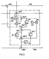
- FIG. 5 shows the functional diagram of a steam pressure regulator with which this requirement is met.
- the control difference "vapor pressure" at the output of the subtractor SUB8 is an amplitude-dependent attenuator, e.g. B. a so-called dead band TD, whose dead zone, in which the damping is 100 S, can be set with an actuator ST8.
- the output signal of the dead band TD is multiplied by the multiplexer M2 by the setpoint for the valve opening of the turbine and the signal thus obtained is subtracted from the setpoint for the electrical power in the subtractor SUB3 and added to the setpoint for the steam generator in the adder ADD8.
- the two inputs of a subtractor SUB10 are connected to the output and the input of the dead band TD, to which a differentiator DF4 and a multiplier M7 are connected.
- the time constant of the differentiator DF4 is set to that of the steam accumulator. Its output signal is added to the signal of the multiplier M2 in an adder ADD13.
- the output signal of the subtractor SUB10 is multiplier M7 with a constant, e.g. B. 0.2 ... 0.3, multiplied and added to the setpoint for the steam generator via adders ADD12 and ADD8.
- the dead zone of the dead band TD is set to zero.
- the input and output signals of the dead band are the same, and the output signal of the subtractor SUB10 is zero.
- the differentiator DF4 and the multiplier M7 thus have no effect on the control.
- the steam pressure regulator according to FIG. 5 then works like that described in FIG. 1.
- the dead zone of the dead band TD is set so large that the largest expected dif Reference signal at the output of the subtractor SUBB is not passed and thus the compensation signal to the subtractor SUB3 is zero.
- the steam pressure remains constant. If there is a difference, the rate of change in pressure caused by this only depends on the storage time constant of the steam generator. Accordingly, the control difference "steam flow” is simulated via the differentiator DF4 with the control difference "steam pressure” as an input signal.
- the control difference "steam flow rate” determined in this way is applied to the steam pressure regulator via the adders ADD13, ADD4, ADD12 and ADD8.
- the electrical output can only be kept constant as long as the valve opening of the turbine remains in the control range. If the valve is fully opened in the event of a major disturbance in steam generation, the degree of compensation of the controlled system changes from 0 to 100 ä. Without taking this limit case into account, the steam pressure regulator would work more slowly than the controlled system allows, but the control would remain stable. However, since the change in the degree of compensation at 100% valve opening is already taken into account when the pressure setpoint is controlled with the connection of the “pressure bump” described with reference to FIG. 1, the steam pressure regulator also works optimally in this limit case.
- the degree of compensation is to be changed depending on the size of the disturbance, that is to say the control difference "vapor pressure”
- a amplitude-dependent attenuator are used, the attenuation of which is large for small amplitudes and small for large amplitudes.
- the above-mentioned dead band is used as the amplitude-dependent attenuator, the electrical power is quickly corrected within a certain bandwidth by adjusting the valve opening and the valve opening of the turbine is kept constant outside this bandwidth.
- the control difference "vapor pressure” is greater than the dead zone set on the dead band, the difference between the input and output signal of the dead band and thus also the output of the subtractor SUB10 remains constant.
Landscapes
- Engineering & Computer Science (AREA)
- Chemical & Material Sciences (AREA)
- Combustion & Propulsion (AREA)
- Mechanical Engineering (AREA)
- General Engineering & Computer Science (AREA)
- Control Of Turbines (AREA)
- Control Of Eletrric Generators (AREA)
Priority Applications (1)
| Application Number | Priority Date | Filing Date | Title |
|---|---|---|---|
| AT83110099T ATE35166T1 (de) | 1982-11-11 | 1983-10-10 | Verfahren zum regeln eines kraftwerkblockes. |
Applications Claiming Priority (2)
| Application Number | Priority Date | Filing Date | Title |
|---|---|---|---|
| DE3241799 | 1982-11-11 | ||
| DE3241799 | 1982-11-11 |
Publications (3)
| Publication Number | Publication Date |
|---|---|
| EP0108928A2 true EP0108928A2 (fr) | 1984-05-23 |
| EP0108928A3 EP0108928A3 (en) | 1985-09-25 |
| EP0108928B1 EP0108928B1 (fr) | 1988-06-15 |
Family
ID=6177921
Family Applications (1)
| Application Number | Title | Priority Date | Filing Date |
|---|---|---|---|
| EP83110099A Expired EP0108928B1 (fr) | 1982-11-11 | 1983-10-10 | Méthode de régulation d'une centrale de force motrice |
Country Status (3)
| Country | Link |
|---|---|
| EP (1) | EP0108928B1 (fr) |
| AT (1) | ATE35166T1 (fr) |
| DE (1) | DE3377072D1 (fr) |
Cited By (6)
| Publication number | Priority date | Publication date | Assignee | Title |
|---|---|---|---|---|
| DE3541148A1 (de) * | 1985-11-21 | 1987-05-27 | Gutehoffnungshuette Man | Verfahren zur regelung einer dampfturbine |
| EP0213351A3 (fr) * | 1985-08-07 | 1989-02-01 | Man Gutehoffnungshütte Gmbh | Procédé et dispositif de régulation d'une turbine à vapeur d'une centrale thermique |
| DE19828446C1 (de) * | 1998-06-26 | 1999-09-23 | Hartmann & Braun Gmbh & Co Kg | Verfahren zur koordinierten Regelung eines Dampfkraftwerksblockes |
| WO2015028366A3 (fr) * | 2013-08-28 | 2015-05-07 | Siemens Aktiengesellschaft | Procédé permettant de faire fonctionner un générateur de vapeur à circulation forcée chauffé par l'extérieur |
| CN108678821A (zh) * | 2018-05-11 | 2018-10-19 | 华电能源股份有限公司富拉尔基发电厂 | 一种实现火电机组热电解耦的汽轮机启停调峰供热系统 |
| CN113406883A (zh) * | 2021-06-28 | 2021-09-17 | 广东电网有限责任公司 | 一种开度指令的生成方法及其装置 |
Family Cites Families (5)
| Publication number | Priority date | Publication date | Assignee | Title |
|---|---|---|---|---|
| US3338054A (en) * | 1964-12-29 | 1967-08-29 | Combustion Eng | Method and apparatus for increasing control response of a vapor generator |
| US3802189A (en) * | 1972-01-13 | 1974-04-09 | Leeds & Northrup Co | Boiler-turbine control system |
| JPS53102405A (en) * | 1977-02-18 | 1978-09-06 | Hitachi Ltd | Speed governing of steam turbine |
| DE2730415C2 (de) * | 1977-07-06 | 1983-02-24 | Saarbergwerke AG, 6600 Saarbrücken | Verfahren zur pendelungsfreien Regelung eines Kraftwerksblocks im gesteuerten Gleitdruck |
| DE2903658A1 (de) * | 1979-01-31 | 1980-08-07 | Siemens Ag | Verfahren und anordnung zum regeln eines kraftwerkblockes |
-
1983
- 1983-10-10 EP EP83110099A patent/EP0108928B1/fr not_active Expired
- 1983-10-10 DE DE8383110099T patent/DE3377072D1/de not_active Expired
- 1983-10-10 AT AT83110099T patent/ATE35166T1/de not_active IP Right Cessation
Cited By (7)
| Publication number | Priority date | Publication date | Assignee | Title |
|---|---|---|---|---|
| EP0213351A3 (fr) * | 1985-08-07 | 1989-02-01 | Man Gutehoffnungshütte Gmbh | Procédé et dispositif de régulation d'une turbine à vapeur d'une centrale thermique |
| DE3541148A1 (de) * | 1985-11-21 | 1987-05-27 | Gutehoffnungshuette Man | Verfahren zur regelung einer dampfturbine |
| DE19828446C1 (de) * | 1998-06-26 | 1999-09-23 | Hartmann & Braun Gmbh & Co Kg | Verfahren zur koordinierten Regelung eines Dampfkraftwerksblockes |
| WO2015028366A3 (fr) * | 2013-08-28 | 2015-05-07 | Siemens Aktiengesellschaft | Procédé permettant de faire fonctionner un générateur de vapeur à circulation forcée chauffé par l'extérieur |
| CN108678821A (zh) * | 2018-05-11 | 2018-10-19 | 华电能源股份有限公司富拉尔基发电厂 | 一种实现火电机组热电解耦的汽轮机启停调峰供热系统 |
| CN113406883A (zh) * | 2021-06-28 | 2021-09-17 | 广东电网有限责任公司 | 一种开度指令的生成方法及其装置 |
| CN113406883B (zh) * | 2021-06-28 | 2022-08-12 | 广东电网有限责任公司 | 一种开度指令的生成方法及其装置 |
Also Published As
| Publication number | Publication date |
|---|---|
| EP0108928A3 (en) | 1985-09-25 |
| DE3377072D1 (en) | 1988-07-21 |
| EP0108928B1 (fr) | 1988-06-15 |
| ATE35166T1 (de) | 1988-07-15 |
Similar Documents
| Publication | Publication Date | Title |
|---|---|---|
| DE3116340C2 (de) | Verfahren und Regeleinrichtung zum Begrenzen der bei Belastungsänderungen auftretenden thermischen Beanspruchung von Bauteilen einer Dampfturbine | |
| DE3023550C2 (fr) | ||
| EP0066651B1 (fr) | Procédé et appareil pour commander un turbogénérateur | |
| DE3304292C2 (fr) | ||
| EP3655663A1 (fr) | Procédé de réglage d'au moins deux ventilateurs | |
| EP0108928B1 (fr) | Méthode de régulation d'une centrale de force motrice | |
| EP3542229B1 (fr) | Dispositif et procédé de détermination des paramètres d'un dispositif de réglage | |
| DE3632041A1 (de) | Verfahren und einrichtung zur regelung der leistung eines dampfkraftwerkblocks | |
| EP1490735B1 (fr) | Procede et regulateur permettant la regulation adaptative d'au moins une composante d'une installation technique | |
| DE2707974A1 (de) | Verfahren und einrichtung zur regelung einer dampfturbinenanlage | |
| DE3541148C3 (de) | Verfahren zur Regelung einer Dampfturbine | |
| DE3714423C2 (fr) | ||
| DE3910869C2 (de) | Reglereinheit für Gasturbinen | |
| DE102016203123A1 (de) | Vorrichtung und Verfahren zur Regelung eines Wechselrichters | |
| DE112019000330T5 (de) | Steuervorrichtung für eine gasturbine, gasturbine und verfahren zum steuern einer gasturbine | |
| WO2022268785A1 (fr) | Dispositif de commande en boucle fermée pour la commande en boucle fermée d'un ensemble d'alimentation comprenant un moteur à combustion interne et un générateur ayant un raccordement d'entraînement fonctionnel au moteur à combustion interne, agencement de commande en boucle fermée doté d'un tel dispositif de commande en boucle fermée, et procédé de commande en boucle fermée d'un ensemble d'alimentation | |
| EP4359657A1 (fr) | Dispositif de régulation pour réguler un système de puissance comprenant un moteur à combustion interne et un générateur en liaison fonctionnelle d'entraînement avec le moteur à combustion interne, système de régulation comprenant un tel dispositif de régulation, système de puissance et procédé pour réguler un système de puissance | |
| EP4330529A1 (fr) | Dispositif de commande en boucle fermée pour la commande en boucle fermée d'un ensemble d'alimentation comprenant un moteur à combustion interne et un générateur présentant un raccordement d'entraînement fonctionnel au moteur à combustion interne, agencement de commande en boucle fermée doté d'un tel dispositif de commande en boucle fermée, et procédé de commande en boucle fermée d'un ensemble d'alimentation | |
| DE19510342C2 (de) | Verfahren zum Regeln der Ausgangsgröße eines Kraftwerksparks | |
| DE2903658A1 (de) | Verfahren und anordnung zum regeln eines kraftwerkblockes | |
| DE893080C (de) | Gleichstromhochspannungskraftuebertragungsanlage | |
| DE19635981C2 (de) | Verfahren zur direkten Regelung der Geschwindigkeit eines elektrischen Antriebes | |
| EP0281788B1 (fr) | Méthode et circuit de réglage autonome des composantes d'un vecteurs de courant | |
| DE1638599A1 (de) | Verfahren zur Steuerung der Drehzahl und Drehrichtung einer Drehstrommaschine | |
| DE974867C (de) | Magnetregler mit mehreren, durch vorgespannte Gleichrichter abwechselnd wirksam gemachten Steuerwicklungen |
Legal Events
| Date | Code | Title | Description |
|---|---|---|---|
| PUAI | Public reference made under article 153(3) epc to a published international application that has entered the european phase |
Free format text: ORIGINAL CODE: 0009012 |
|
| AK | Designated contracting states |
Designated state(s): AT CH DE IT LI NL SE |
|
| 17P | Request for examination filed |
Effective date: 19841220 |
|
| PUAL | Search report despatched |
Free format text: ORIGINAL CODE: 0009013 |
|
| AK | Designated contracting states |
Designated state(s): AT CH DE IT LI NL SE |
|
| 17Q | First examination report despatched |
Effective date: 19861024 |
|
| GRAA | (expected) grant |
Free format text: ORIGINAL CODE: 0009210 |
|
| AK | Designated contracting states |
Kind code of ref document: B1 Designated state(s): AT CH DE IT LI NL SE |
|
| REF | Corresponds to: |
Ref document number: 35166 Country of ref document: AT Date of ref document: 19880715 Kind code of ref document: T |
|
| PG25 | Lapsed in a contracting state [announced via postgrant information from national office to epo] |
Ref country code: SE Effective date: 19880630 |
|
| REF | Corresponds to: |
Ref document number: 3377072 Country of ref document: DE Date of ref document: 19880721 |
|
| ITF | It: translation for a ep patent filed | ||
| PLBE | No opposition filed within time limit |
Free format text: ORIGINAL CODE: 0009261 |
|
| STAA | Information on the status of an ep patent application or granted ep patent |
Free format text: STATUS: NO OPPOSITION FILED WITHIN TIME LIMIT |
|
| 26N | No opposition filed | ||
| ITTA | It: last paid annual fee | ||
| PGFP | Annual fee paid to national office [announced via postgrant information from national office to epo] |
Ref country code: AT Payment date: 20021004 Year of fee payment: 20 |
|
| PGFP | Annual fee paid to national office [announced via postgrant information from national office to epo] |
Ref country code: NL Payment date: 20021021 Year of fee payment: 20 |
|
| PGFP | Annual fee paid to national office [announced via postgrant information from national office to epo] |
Ref country code: DE Payment date: 20021216 Year of fee payment: 20 |
|
| PGFP | Annual fee paid to national office [announced via postgrant information from national office to epo] |
Ref country code: CH Payment date: 20030115 Year of fee payment: 20 |
|
| PG25 | Lapsed in a contracting state [announced via postgrant information from national office to epo] |
Ref country code: LI Free format text: LAPSE BECAUSE OF EXPIRATION OF PROTECTION Effective date: 20031009 Ref country code: CH Free format text: LAPSE BECAUSE OF EXPIRATION OF PROTECTION Effective date: 20031009 |
|
| PG25 | Lapsed in a contracting state [announced via postgrant information from national office to epo] |
Ref country code: NL Free format text: LAPSE BECAUSE OF EXPIRATION OF PROTECTION Effective date: 20031010 Ref country code: AT Free format text: LAPSE BECAUSE OF EXPIRATION OF PROTECTION Effective date: 20031010 |
|
| REG | Reference to a national code |
Ref country code: CH Ref legal event code: PL |
|
| NLV7 | Nl: ceased due to reaching the maximum lifetime of a patent |
Effective date: 20031010 |