EP0108930A2 - Accouplement protégé contre la surcharge - Google Patents
Accouplement protégé contre la surcharge Download PDFInfo
- Publication number
- EP0108930A2 EP0108930A2 EP83110148A EP83110148A EP0108930A2 EP 0108930 A2 EP0108930 A2 EP 0108930A2 EP 83110148 A EP83110148 A EP 83110148A EP 83110148 A EP83110148 A EP 83110148A EP 0108930 A2 EP0108930 A2 EP 0108930A2
- Authority
- EP
- European Patent Office
- Prior art keywords
- overload protection
- suspension section
- protection according
- annular space
- section
- Prior art date
- Legal status (The legal status is an assumption and is not a legal conclusion. Google has not performed a legal analysis and makes no representation as to the accuracy of the status listed.)
- Granted
Links
Images


Classifications
-
- F—MECHANICAL ENGINEERING; LIGHTING; HEATING; WEAPONS; BLASTING
- F16—ENGINEERING ELEMENTS AND UNITS; GENERAL MEASURES FOR PRODUCING AND MAINTAINING EFFECTIVE FUNCTIONING OF MACHINES OR INSTALLATIONS; THERMAL INSULATION IN GENERAL
- F16D—COUPLINGS FOR TRANSMITTING ROTATION; CLUTCHES; BRAKES
- F16D7/00—Slip couplings, e.g. slipping on overload, for absorbing shock
- F16D7/04—Slip couplings, e.g. slipping on overload, for absorbing shock of the ratchet type
- F16D7/048—Slip couplings, e.g. slipping on overload, for absorbing shock of the ratchet type with parts moving radially between engagement and disengagement
-
- F—MECHANICAL ENGINEERING; LIGHTING; HEATING; WEAPONS; BLASTING
- F16—ENGINEERING ELEMENTS AND UNITS; GENERAL MEASURES FOR PRODUCING AND MAINTAINING EFFECTIVE FUNCTIONING OF MACHINES OR INSTALLATIONS; THERMAL INSULATION IN GENERAL
- F16D—COUPLINGS FOR TRANSMITTING ROTATION; CLUTCHES; BRAKES
- F16D7/00—Slip couplings, e.g. slipping on overload, for absorbing shock
- F16D7/04—Slip couplings, e.g. slipping on overload, for absorbing shock of the ratchet type
- F16D7/06—Slip couplings, e.g. slipping on overload, for absorbing shock of the ratchet type with intermediate balls or rollers
- F16D7/10—Slip couplings, e.g. slipping on overload, for absorbing shock of the ratchet type with intermediate balls or rollers moving radially between engagement and disengagement
Definitions
- the invention relates to an overload protection on couplings, with drive and output elements arranged concentrically to one another and with a driving body provided in the intermediate space of these elements and interacting with a spring.
- Overload safety devices are known in which the cylindrical drive body is pivoted on one arm of a double-armed lever and is immersed in a notch-like recess in a ring surrounding it ("Hütte", Ingenieur practice Taschenbuch II, 27th edition).
- a tension spring acts on the other arm of the lever and loads the entraining body in the direction of engagement. If the limit torque is exceeded, the entrainment body disengages from the recess and thus separates the input and output.
- This configuration is complex in its construction and requires a larger space. It is therefore not very suitable for use in small motor-driven devices.
- the object of the invention is based on the design of an overload protection of the type required in a technically simple manner so that it works reliably in a small design.
- This object is achieved in that the uncoupling position is achieved by bending a suspension section crossing the intermediate space.
- the electric motor and the drive elements are therefore protected while increasing the life of the device. After eliminating the source of the error, the overload protection is ready for use without special handling.
- the transmission range of the clutch can be determined by the position and design of the suspension section. A lubricant may also be added.
- the space between the drive and driven element is designed as an annular space, the cross section of which is reduced at least at one point by means of a suspension section to a dimension smaller than the diameter of the entraining body rotating in the annular space.
- the driver body can be designed as a rolling body. Different types of rolling elements can be used. These can have the shape of a barrel, roller or ball, for example.
- the suspension section could also be adjusted.
- suspension section is formed by a leaf spring arranged in the form of a secant to the annular space. This can be created inexpensively and easily accommodated in terms of assembly technology.
- a variant is characterized in that several leaf springs lying at an angle to one another are provided one behind the other in the circumferential direction of the annular space.
- the entrainment body is positively held in a clamping position after the switch-on jerk.
- the arrangement of the leaf spring can be such that the reduction in cross section increases.
- leaf spring lies in a slot in the wall of a sleeve forming the annular space wall with its inner surface, which forms the drive element.
- suspension section from a leaf spring that extends spirally into the annular space for bouncing-free coupling of the entrainment body.
- An advantageous embodiment also consists in the fact that an outwardly directed evasive space for the entrainment body is arranged downstream of the reduced-section location. After the limit torque has been exceeded, the input and output elements still run at the input speed. However, immediately after disengaging or overcoming the suspension section, the entrainment body is pressed against the outer raceway by centrifugal force, enters the evasive space and is therefore no longer in contact with the output element and, in this position, rotates freely with the drive. After switching off the device, the entrainment body is still in the escape room. Only the switch-on jerk, caused by the inertia of the entrainment body, leads to a renewed entrainment of the same and thus the clutch closing.
- Another design in which the production is further simplified, less assembly work and a more wear-free operation is achieved, is characterized in that the entrainment body is formed by a cam assigned to the drive shaft, the apex height of which is greater than the dimension of the Annulus in its reduced area.
- cam is designed as a molded part of a ring arranged on the drive shaft in a rotationally fixed manner.
- the suspension section is designed as a bimetallic strip in such a way that the resulting from the grinding movement between the suspension section and the cam Heating bends the suspension section in the uncoupling position. This heating only takes place when the cam slips repeatedly under the bimetal strip. The transmission system is then completely disengaged until the bimetal strip has cooled down again.
- the bimetallic strip is arranged so that the more expanding metal strip faces away from the cam. Both ends of the bimetal strip can be firmly anchored. However, it turns out to be more favorable if only one end is fixed and the other end is movable.
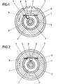
- the number 1 denotes a gearwheel which is rotated in the direction of arrow x by a gear unit (not shown) of a small electrical device.
- This gearwheel 1 is non-rotatably seated on a drive element 2 which is formed by a bush and which is arranged concentrically with an annular output element 4 while leaving an annular space 3.
- the cross section of the annular space 3 is reduced at one point by means of a suspension section 5.
- the suspension section 5 is formed by a leaf spring arranged in a secant shape relative to the annular space 3. This lies in a slot 6 of the wall of the sleeve 2 forming the annular space wall 2 'with its inner surface. The slot 6 continues into that Gear 1 reaching insertion niches 7 for the ends 5 'of the leaf spring 5 on.
- a driving body 8 which is adapted to this in diameter.
- the latter is designed as a ball.
- the entrainment body 8 reaches the wedging position between the suspension section 5 and the output element 4 as shown in FIG. 1 when the switch-on jerk occurs. Then a slip-free transmission of the drive power to the output element 4 occurs achieved by a greater resistance on the output element 4, the entrainment body 8 overcomes the suspension section 5 by pressing it into the slot 6 according to FIG. Then the entrainment body 8 again enters the annular space 3 and, due to its inertia, returns to the position shown in FIG. 1 and again overcomes the area of the annular space 3 which is reduced in cross-section by the leaf spring serves.
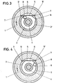
- the structure of the second embodiment shown in FIGS. 3 and 4 corresponds essentially to that of the first embodiment.
- the same components therefore have the same reference symbols.
- the area reduced by the leaf spring 5 is followed by an outwardly directed escape space 9 for the spherical entrainment body 8.
- the escape space 9 is located in the annular space wall 2 'and is adapted to the curvature of the entrainment body 8.
- the entrainment body 8 arrives in the evacuation space 9 and remains there due to centrifugal force of the rotating bush 2.
- the evacuation space 9 is dimensioned so deep that the entrainment body receives no contact with the circumferential surface of the ring-like output element 4. If the device is stopped when a limit value is exceeded and switched on again, it leaves of the switch-on jerk of the entraining body 8, the escape space 9 and reaches the entraining position according to FIG. 3.
- FIGS. 5 and 6 The third embodiment illustrated in FIGS. 5 and 6 is designed similarly to the previous ones. There are now three leaf springs 10, 11 and 12 lying at an angle to one another. Each leaf spring 10, 11, 12 has its own escape slot 13, 14, 15. Both the leaf springs 10-12 and the escape slots 13-15 have different lengths. In this way it is possible for the shortest leaf spring 10 to bring about a smaller reduction in the cross section of the annular space 3. The subsequent leaf springs 11, 12 lead to a step-like cross-sectional reduction of the annular space 3, the cross-sectional reduction being greatest in the area of the leaf spring 12. The driving body 8 must therefore, as shown in Fig. 6, overcome the successive cross-sectional reductions. If he has completed all the cross-sectional reductions caused by the leaf springs 10-12, he arrives in a subordinate escape space 9.
- the suspension section is formed by a leaf spring 16 which extends spirally into the annular space 3 in such a way that the reduction in cross section increases towards the end 16 'of the leaf spring.
- the other end 16 ′′ lies in a radial groove 17 of the sleeve-shaped drive element 18.
- the greater the resistance the further the entrainment body 8 reaches the free end 16 ′ of the leaf spring 16. If the section modulus on the output element 4 is too great, it is overcome the entrainment body 8 completely reduces the cross-section caused by the leaf spring 16, the leaf spring 16 inevitably immersing in the arch slot 19 of the bush 18 assigned to it, see FIG. 8.
- the drive shaft driven by a device motor is designated by the number 20.
- a ring 23 is seated on this drive shaft 20 in a non-rotatable manner.
- a feather key 24 is used for non-rotatability.
- the ring 23 forms an annular space 26 in connection with an output element 25 which is concentrically disposed therewith.
- the suspension section 27 is formed by a leaf spring arranged in the form of a secant to the annular space 26. This lies with its ends 27 'in slots 28 of the inner sleeve 25' of the output element 25.
- the cross-sectional reduction of the annular space 26 is dimensioned so large that the ring 23 is adjacent to the suspension section 27 with its peripheral surface.
- the suspension section 27 interacts with a cam 29, which starts from the ring 23 and forms the entrainment body, and is formed by shaping the ring 23.
- the cam 29 extends at the level of the feather key 24.
- the apex height y of the cam is greater than the dimension of the annular space 26 in its area reduced by the suspension section 27.
- the cam 29 first comes into contact with the suspension section 27 and takes the driven element 25 with it. If the maximum force limited by the apex height of the cam and spring strength is exceeded, the case according to FIG. 10 occurs, with the cam 29 deflecting the suspension section 27. The cam 29 then moves away from the suspension section 27 in the direction of rotation. Until the cam 29 contacts the suspension section 27 again, there is no contact between these two parts. As it continues to rotate, the cam 29 comes into contact with the suspension portion 27 again and the transmission system is in engagement again. If the load torque has not yet dropped below the maximum permissible value, the process described above is repeated. Here This creates a noise that draws the user's attention to an excessive load on the device equipped with the coupling.
- a further modification is possible in that a bimetal strip is used instead of the suspension section 27 in such a way that its more expanding metal strip faces away from the cam 29. Both ends of the bimetal strip can then be firmly anchored to the output element 25. It turns out to be a cheaper solution to firmly anchor only one end and make the other end movable. If the limit torque is exceeded, the constant slippage of the cam on the underside of the bimetallic strip then heats it up, so that it then bends in the outward direction. Then there is no contact between the cam and the bimetallic strip. The transmission system is now completely disengaged until the bimetal strip has cooled down again.
- cams and suspension sections instead of two cams and two suspension sections, it would also be possible to provide more cams and suspension sections in the same angular distribution. Then larger torques can be added transfer smaller loads from cams and suspension sections.
Landscapes
- Engineering & Computer Science (AREA)
- General Engineering & Computer Science (AREA)
- Mechanical Engineering (AREA)
- One-Way And Automatic Clutches, And Combinations Of Different Clutches (AREA)
- Mechanical Operated Clutches (AREA)
Priority Applications (1)
| Application Number | Priority Date | Filing Date | Title |
|---|---|---|---|
| AT83110148T ATE24230T1 (de) | 1982-11-13 | 1983-10-12 | Ueberlastsicherung an kupplungen. |
Applications Claiming Priority (4)
| Application Number | Priority Date | Filing Date | Title |
|---|---|---|---|
| DE3242046 | 1982-11-13 | ||
| DE19823242046 DE3242046A1 (de) | 1982-11-13 | 1982-11-13 | Ueberlastsicherung an kupplungen |
| DE3335729 | 1983-10-01 | ||
| DE19833335729 DE3335729A1 (de) | 1983-10-01 | 1983-10-01 | Ueberlast-sicherung an kupplungen |
Publications (3)
| Publication Number | Publication Date |
|---|---|
| EP0108930A2 true EP0108930A2 (fr) | 1984-05-23 |
| EP0108930A3 EP0108930A3 (en) | 1984-07-25 |
| EP0108930B1 EP0108930B1 (fr) | 1986-12-10 |
Family
ID=25805739
Family Applications (1)
| Application Number | Title | Priority Date | Filing Date |
|---|---|---|---|
| EP83110148A Expired EP0108930B1 (fr) | 1982-11-13 | 1983-10-12 | Accouplement protégé contre la surcharge |
Country Status (5)
| Country | Link |
|---|---|
| US (1) | US4610340A (fr) |
| EP (1) | EP0108930B1 (fr) |
| AU (1) | AU2051883A (fr) |
| DE (1) | DE3368310D1 (fr) |
| ES (1) | ES527211A0 (fr) |
Cited By (4)
| Publication number | Priority date | Publication date | Assignee | Title |
|---|---|---|---|---|
| EP0559918A4 (fr) * | 1991-09-30 | 1994-04-06 | Ntn Corporation | |
| FR2697067A1 (fr) * | 1992-10-19 | 1994-04-22 | Rafaut & Cie | Dispositif pour commander la transmission de mouvement entre un noyau monté à rotation sur lui-même et une vis sans fin dont la rotation commande mécaniquement la rotation du noyau. |
| WO1994011646A1 (fr) * | 1992-11-17 | 1994-05-26 | Bendix Espana S.A. | Dispositif elastique de centrage et d'accouplement a course morte de deux organes rotatifs |
| US7155773B2 (en) | 2003-04-16 | 2007-01-02 | Alfred Kaercher Gmbh & Co. Kg | Cleaning head for floor cleaning device |
Families Citing this family (15)
| Publication number | Priority date | Publication date | Assignee | Title |
|---|---|---|---|---|
| DE3911303C1 (fr) * | 1989-04-07 | 1990-08-23 | Braun Ag, 6000 Frankfurt, De | |
| US5346023A (en) * | 1993-02-11 | 1994-09-13 | Hitachi Koki Company Limited | Slipping torque changing apparatus for impact tool |
| DE4306212C2 (de) * | 1993-02-27 | 1994-12-08 | Kiekert Gmbh Co Kg | Elektromechanischer Antrieb für eine Zentralverriegelungsvorrichtung für Kraftfahrzeugtürverschlüsse |
| US5337971A (en) * | 1993-03-31 | 1994-08-16 | Eastman Kodak Company | Torque transmission clutch for film spool |
| US5386897A (en) * | 1993-05-27 | 1995-02-07 | Yang; Tai-Her | Delay restoring type limit-torque coupling mechanism |
| JP2910599B2 (ja) * | 1995-01-26 | 1999-06-23 | ノーリツ鋼機株式会社 | トルク制御装置 |
| US6196332B1 (en) * | 1998-12-03 | 2001-03-06 | Ingersoll-Rand Company | Rotational energy storage device and tools incorporating same |
| AUPP924899A0 (en) * | 1999-03-17 | 1999-04-15 | Igc (Australia) Pty Ltd | A braking attachment |
| IT1308293B1 (it) * | 1999-07-29 | 2001-12-10 | Edi Bondioli | Giunto di trasmissione e limitatore di coppia perfezionato |
| JP2001343025A (ja) * | 2000-03-29 | 2001-12-14 | Toyota Industries Corp | 動力伝達機構 |
| SE520640C2 (sv) * | 2001-10-16 | 2003-08-05 | Atlas Copco Tools Ab | Handhållet kraftverktyg med en roterande utgående axel |
| FR2879540B1 (fr) * | 2004-12-17 | 2008-07-11 | Valeo Systemes Dessuyage | Agencement de liaison debrayable d'un bras d'essuie glace sur un arbre moteur |
| US9604602B2 (en) | 2013-02-07 | 2017-03-28 | Trico Products Corporation | Wiper motor drive system having breakaway clutch |
| US12071995B2 (en) * | 2018-07-24 | 2024-08-27 | Borgwarner Inc. | Torque limiting coupler for an electric motor shaft |
| US12000448B2 (en) * | 2019-09-20 | 2024-06-04 | Pacesetter, Inc. | Biostimulator transport system having torque limiter |
Family Cites Families (28)
| Publication number | Priority date | Publication date | Assignee | Title |
|---|---|---|---|---|
| US913475A (en) * | 1908-09-19 | 1909-02-23 | Charles E Troemner | Coffee-mill. |
| US1704503A (en) * | 1927-11-30 | 1929-03-05 | Borg & Beck Co | Clutch plate |
| US1896025A (en) * | 1928-03-17 | 1933-01-31 | Packard Motor Car Co | Motor vehicle clutch |
| US1962993A (en) * | 1930-10-16 | 1934-06-12 | Leece Neville Co | Spring drive |
| US2023690A (en) * | 1932-11-25 | 1935-12-10 | Kenneth E Lyman | Automatic clutch |
| US2143710A (en) * | 1937-05-01 | 1939-01-10 | Howard J Murray | Automatic self-energizing clutch |
| US2461447A (en) * | 1943-06-30 | 1949-02-08 | Josephine M Siesel | Yielding drive |
| US2493232A (en) * | 1945-09-08 | 1950-01-03 | Adiel Y Dodge | Coupling |
| US2637987A (en) * | 1947-02-18 | 1953-05-12 | Hil Jon Safety Crown Corp | Overload release coupling |
| DE809877C (de) * | 1948-10-02 | 1951-08-02 | G Boley Fa | Rasteneinrichtung |
| GB661643A (en) * | 1948-11-19 | 1951-11-21 | Stanley Morton | Improvements in and relating to shaft couplings |
| FR1034596A (fr) * | 1950-09-11 | 1953-07-27 | Entraîneur limiteur d'effort | |
| US2688857A (en) * | 1953-07-29 | 1954-09-14 | Jones Motrola Corp | Safety coupling for flexible shafting |
| US2826903A (en) * | 1955-03-08 | 1958-03-18 | Centric Clutch Company | Overload release clutch |
| US2854830A (en) * | 1956-05-14 | 1958-10-07 | Gorton George Machine Co | Safety clutch |
| CH337705A (fr) * | 1956-08-20 | 1959-04-15 | Scully Jones & Co | Mandrin à couple de torsion limité |
| DE1182910B (de) * | 1957-04-02 | 1964-12-03 | Lauravia S A | Drehmomentbegrenzer |
| FR2055158A6 (fr) * | 1967-04-19 | 1971-05-07 | Bouhot Marcel | |
| US3618310A (en) * | 1970-04-15 | 1971-11-09 | Gen Electric | Clock timer with sleep switch |
| US3752277A (en) * | 1970-10-27 | 1973-08-14 | S Nakai | Torque clutch mechanism in an air wrench |
| SU396480A1 (ru) * | 1971-06-17 | 1973-08-29 | Фрикционная предохранительная муфта | |
| FR2221975A5 (en) * | 1973-03-16 | 1974-10-11 | Riou Michel | Versatile flexible coupling and torque limiter - has rugged two part device plug unique female spring element |
| SU451876A1 (ru) * | 1973-06-15 | 1974-11-30 | Предприятие П/Я А-1575 | Предохранительна муфта |
| US4043437A (en) * | 1975-12-19 | 1977-08-23 | Lipe-Rollway Corporation | Torque limiting clutch brake |
| DE2853900A1 (de) * | 1978-12-14 | 1980-06-26 | Porsche Ag | Vorrichtung zur betaetigung von kraftfahrzeugkupplungen |
| PL218437A1 (fr) * | 1979-09-19 | 1981-04-10 | Przemyslowy Inst Maszyn Rol | |
| US4327563A (en) * | 1979-11-07 | 1982-05-04 | Allmacher Jr Daniel S | Torque-limiting drive coupling |
| SU868177A1 (ru) * | 1980-02-01 | 1981-09-30 | Вильнюсский Инженерно-Строительный Институт | Упруго-центробежна муфта |
-
1983
- 1983-10-12 DE DE8383110148T patent/DE3368310D1/de not_active Expired
- 1983-10-12 EP EP83110148A patent/EP0108930B1/fr not_active Expired
- 1983-10-24 AU AU20518/83A patent/AU2051883A/en not_active Abandoned
- 1983-10-31 US US06/547,315 patent/US4610340A/en not_active Expired - Fee Related
- 1983-11-11 ES ES527211A patent/ES527211A0/es active Granted
Cited By (5)
| Publication number | Priority date | Publication date | Assignee | Title |
|---|---|---|---|---|
| EP0559918A4 (fr) * | 1991-09-30 | 1994-04-06 | Ntn Corporation | |
| US5672110A (en) * | 1991-09-30 | 1997-09-30 | Ntn Corporation | Torque limiter having automatic reset function |
| FR2697067A1 (fr) * | 1992-10-19 | 1994-04-22 | Rafaut & Cie | Dispositif pour commander la transmission de mouvement entre un noyau monté à rotation sur lui-même et une vis sans fin dont la rotation commande mécaniquement la rotation du noyau. |
| WO1994011646A1 (fr) * | 1992-11-17 | 1994-05-26 | Bendix Espana S.A. | Dispositif elastique de centrage et d'accouplement a course morte de deux organes rotatifs |
| US7155773B2 (en) | 2003-04-16 | 2007-01-02 | Alfred Kaercher Gmbh & Co. Kg | Cleaning head for floor cleaning device |
Also Published As
| Publication number | Publication date |
|---|---|
| ES8406657A1 (es) | 1984-08-01 |
| AU2051883A (en) | 1984-05-17 |
| ES527211A0 (es) | 1984-08-01 |
| US4610340A (en) | 1986-09-09 |
| DE3368310D1 (en) | 1987-01-22 |
| EP0108930B1 (fr) | 1986-12-10 |
| EP0108930A3 (en) | 1984-07-25 |
Similar Documents
| Publication | Publication Date | Title |
|---|---|---|
| EP0108930A2 (fr) | Accouplement protégé contre la surcharge | |
| DE1625825C3 (de) | Schaltbare Klemmkörper-Freilaufkupplung | |
| DE2827948C3 (de) | Ausrückkupplung | |
| EP2311397B1 (fr) | Limiteur de couple | |
| DE1239895B (de) | UEberlastsicherheitskupplung | |
| DE2124700A1 (de) | Lineareinstellvorrichtung | |
| DE2802773A1 (de) | Nichtreversible antriebsvorrichtung, insbesondere fuer das kraftuebertragungselement von elektrischen anlassern fuer verbrennungsmotoren | |
| DE3819481C1 (fr) | ||
| DE1525340A1 (de) | Federbandreibungskupplung | |
| DE2836114C2 (de) | Klemmkörperfreilaufkupplung | |
| EP0064763A2 (fr) | Commande, en particulier commande de déplacement dans un véhicule à moteur | |
| DE7924104U1 (de) | Wahlweise einrueckbare und ausrueckbare kupplung | |
| EP1582758B1 (fr) | Dispositif d'accouplement avec des éléments de coincement | |
| DE102007014831B4 (de) | Kupplungsaktuatorik mit einer Unterstützungseinrichtung und Kupplung mit einer solchen Kupplungsaktuatorik | |
| DE1284715B (de) | Schraubenfederband-Kupplung | |
| DE8102255U1 (de) | "kupplungsdrucklager" | |
| DE2452650C2 (de) | Freilaufkupplung mit unrunden Klemmkörpern | |
| DE102007047635A1 (de) | Drehmomentbegrenzungskupplung | |
| DE3146289C2 (fr) | ||
| DE3000659C2 (de) | Vorrichtung zur Ausübung einer geradlinigen Vorschubbewegung | |
| DE1948573C3 (de) | AnlaBmotor für Brennkraftmaschinen | |
| DE69704094T2 (de) | Anlasser mit einer verbesserten Antriebs- und Rückstellvorrichtung des Ritzels | |
| DE3009853B1 (de) | Fliehkraftschaltkupplung | |
| DE3500324C2 (de) | Drehmomentbegrenzungseinrichtung | |
| DE2426167C3 (de) | Fahrrad-Freilaufbremsnabe |
Legal Events
| Date | Code | Title | Description |
|---|---|---|---|
| PUAI | Public reference made under article 153(3) epc to a published international application that has entered the european phase |
Free format text: ORIGINAL CODE: 0009012 |
|
| AK | Designated contracting states |
Designated state(s): AT CH DE FR GB IT LI SE |
|
| PUAL | Search report despatched |
Free format text: ORIGINAL CODE: 0009013 |
|
| AK | Designated contracting states |
Designated state(s): AT CH DE FR GB IT LI SE |
|
| 17P | Request for examination filed |
Effective date: 19841127 |
|
| GRAA | (expected) grant |
Free format text: ORIGINAL CODE: 0009210 |
|
| AK | Designated contracting states |
Kind code of ref document: B1 Designated state(s): AT CH DE FR GB IT LI SE |
|
| REF | Corresponds to: |
Ref document number: 24230 Country of ref document: AT Date of ref document: 19861215 Kind code of ref document: T |
|
| REF | Corresponds to: |
Ref document number: 3368310 Country of ref document: DE Date of ref document: 19870122 |
|
| ET | Fr: translation filed | ||
| ITF | It: translation for a ep patent filed | ||
| PLBE | No opposition filed within time limit |
Free format text: ORIGINAL CODE: 0009261 |
|
| STAA | Information on the status of an ep patent application or granted ep patent |
Free format text: STATUS: NO OPPOSITION FILED WITHIN TIME LIMIT |
|
| 26N | No opposition filed | ||
| ITTA | It: last paid annual fee | ||
| EAL | Se: european patent in force in sweden |
Ref document number: 83110148.0 |
|
| PGFP | Annual fee paid to national office [announced via postgrant information from national office to epo] |
Ref country code: AT Payment date: 19960920 Year of fee payment: 14 |
|
| PGFP | Annual fee paid to national office [announced via postgrant information from national office to epo] |
Ref country code: CH Payment date: 19960923 Year of fee payment: 14 |
|
| PGFP | Annual fee paid to national office [announced via postgrant information from national office to epo] |
Ref country code: FR Payment date: 19960926 Year of fee payment: 14 |
|
| PGFP | Annual fee paid to national office [announced via postgrant information from national office to epo] |
Ref country code: GB Payment date: 19961003 Year of fee payment: 14 |
|
| PGFP | Annual fee paid to national office [announced via postgrant information from national office to epo] |
Ref country code: DE Payment date: 19961004 Year of fee payment: 14 |
|
| PGFP | Annual fee paid to national office [announced via postgrant information from national office to epo] |
Ref country code: SE Payment date: 19961016 Year of fee payment: 14 |
|
| PG25 | Lapsed in a contracting state [announced via postgrant information from national office to epo] |
Ref country code: GB Free format text: LAPSE BECAUSE OF NON-PAYMENT OF DUE FEES Effective date: 19971012 Ref country code: AT Free format text: LAPSE BECAUSE OF NON-PAYMENT OF DUE FEES Effective date: 19971012 |
|
| PG25 | Lapsed in a contracting state [announced via postgrant information from national office to epo] |
Ref country code: SE Free format text: LAPSE BECAUSE OF NON-PAYMENT OF DUE FEES Effective date: 19971013 |
|
| PG25 | Lapsed in a contracting state [announced via postgrant information from national office to epo] |
Ref country code: LI Free format text: LAPSE BECAUSE OF NON-PAYMENT OF DUE FEES Effective date: 19971031 Ref country code: FR Free format text: THE PATENT HAS BEEN ANNULLED BY A DECISION OF A NATIONAL AUTHORITY Effective date: 19971031 Ref country code: CH Free format text: LAPSE BECAUSE OF NON-PAYMENT OF DUE FEES Effective date: 19971031 |
|
| GBPC | Gb: european patent ceased through non-payment of renewal fee |
Effective date: 19971012 |
|
| REG | Reference to a national code |
Ref country code: CH Ref legal event code: PL |
|
| PG25 | Lapsed in a contracting state [announced via postgrant information from national office to epo] |
Ref country code: DE Free format text: LAPSE BECAUSE OF NON-PAYMENT OF DUE FEES Effective date: 19980701 |
|
| EUG | Se: european patent has lapsed |
Ref document number: 83110148.0 |
|
| REG | Reference to a national code |
Ref country code: FR Ref legal event code: ST |