EP0108944A1 - Verdrängerteil einer Kolbenpumpe - Google Patents
Verdrängerteil einer Kolbenpumpe Download PDFInfo
- Publication number
- EP0108944A1 EP0108944A1 EP83110319A EP83110319A EP0108944A1 EP 0108944 A1 EP0108944 A1 EP 0108944A1 EP 83110319 A EP83110319 A EP 83110319A EP 83110319 A EP83110319 A EP 83110319A EP 0108944 A1 EP0108944 A1 EP 0108944A1
- Authority
- EP
- European Patent Office
- Prior art keywords
- piston
- blind hole
- adapter
- threaded
- recess
- Prior art date
- Legal status (The legal status is an assumption and is not a legal conclusion. Google has not performed a legal analysis and makes no representation as to the accuracy of the status listed.)
- Granted
Links
Images

Classifications
-
- F—MECHANICAL ENGINEERING; LIGHTING; HEATING; WEAPONS; BLASTING
- F04—POSITIVE - DISPLACEMENT MACHINES FOR LIQUIDS; PUMPS FOR LIQUIDS OR ELASTIC FLUIDS
- F04B—POSITIVE-DISPLACEMENT MACHINES FOR LIQUIDS; PUMPS
- F04B53/00—Component parts, details or accessories not provided for in, or of interest apart from, groups F04B1/00 - F04B23/00 or F04B39/00 - F04B47/00
- F04B53/14—Pistons, piston-rods or piston-rod connections
- F04B53/144—Adaptation of piston-rods
- F04B53/147—Mounting or detaching of piston rod
Definitions
- the invention relates to a displacement part of a piston pump for abrasive and / or corrosive liquids, consisting of a piston rod and a piston made of an oxide-ceramic material fastened to it by means of a releasable connection, the piston having a blind hole running in the direction of the piston head.
- Pump pistons of high-pressure pumps for washing units are subject to high loads.
- the pumps are generally designed as piston pumps in which 2-6 cylinders work on a crankshaft. They reach pressures that are between 80 and 18o bar. Sharp alkalis are usually used as the cleaning liquid. The temperatures of the cleaning fluids are 80 and more degrees C.
- the coated or hard chrome-plated steel sleeves previously used as pistons were connected to the piston rod by means of a clamping screw. As an alternative to these steel sleeves, corresponding sleeves made of sintered oxide ceramic were used, which were connected in an analogous manner.
- As a metal for the piston rod was a stainless material, so generally a high-alloy steel was used.
- the arrangement of the O-ring for the seal additionally required a chamfer to be ground into the engagement area of the O-ring in the ceramic tube in order to prevent the risk of the O-ring being crushed during assembly.
- the crushing resulted in a defective seal, which led to corrosion within the piston or to the piston being destroyed by higher internal pressure in the suction stroke.
- Even the attachment of the chamfer did not completely prevent the risk of an O-ring being crushed during quick assembly. Because the pistons have to be released after a certain working time in order to remove the worn sealing sleeves that slide on this piston change, it is absolutely necessary that the connection between the piston and the piston rod cannot corrode, that is, must be completely separated from the medium.
- oxide ceramic materials or oxide ceramics in the sense of the present invention is the short name for ceramics of pure oxides, oxide compounds and oxide mixtures, insofar as they are almost free of SiO 2 , this term serving as a differentiation from conventional silicate ceramics.
- this term is understood to mean sintered products made from the oxides of aluminum, beryllium, magnesium, zirconium and thorium, and also from spinel, that is to say MgO Al 2 O 3 .
- the term also includes the titanates and the uranium oxide, as well as the rare earth oxides and also some heavy metal oxides, all of which are used in high purity. However, the term high purity does not exclude that certain percentages of several oxides are mixed together and then sintered.
- Oxide-ceramic materials such as aluminum oxide
- Oxide-ceramic materials are sintered according to the aluminum oxide content of the materials at temperatures above 1500 ° C.
- the parts manufactured as green bodies initially shrink considerably, ie in the range from 18 to 23%.
- this shrinkage is not completely uniform everywhere, especially not if there are different wall thicknesses.
- One must therefore proceed in such a way that the required thread is subsequently grinded in diamond-tipped grinding wheels are introduced or reworked.
- such a complex method cannot be implemented for a simple body such as that represented by a pump piston for reasons of price.
- the prior art therefore envisaged sintering ceramic tubes, which were ground on both ends and could be screwed onto the piston rod by means of a bolt.
- the disadvantage of this construction is the complicated sealing, without which the piston cannot be released. It was also necessary to grind both end faces.
- the invention is therefore based on the object of finding a connection between the piston and the piston rod which can also be released after a long period of time when used in corrosive and abrasive media and to reduce the grinding work during piston production.
- the invention has a number of advantages. First, the number of surfaces to be machined after the piston sintering process is reduced to two, ie only the outer surface and the end face of the piston head have to be machined.
- the blind hole, as well as the recess, are introduced into the piston in the green state and, like the piston crown, do not require any post-processing after the sintering process.
- the tolerances of the blind hole and the recess are therefore relatively large, because the required socket, that is to say the piston is sufficient, is carried out on the adapter.
- a preferred embodiment of the invention provides for the adapter to center the piston head. It is therefore an outer centering of the piston, in which there is enough play for the threaded elements without losing the accuracy of the centering.
- the adapter is expediently provided with a threaded pin which is screwed through the blind hole into the threaded piece.
- the threaded piece itself expediently consists of a simple piece of round steel which is drilled perpendicularly to its longitudinal extent and is threaded. Instead of a round steel, any profile steel can be used that has a threaded hole. It is only important that the threaded pin of the adapter has enough play in the blind hole and that the threaded piece in the recess has enough play to allow attachment.
- the adapter is to be connected to the piston rod, which is expediently carried out by plugging or plugging the piston rod onto or into the adapter; however it is possible to provide this connection as a screw connection.
- the piston 2 made of sintered oxide ceramic has a chamfer 17 in the region of the piston head 3, to which the jacket 6 of the piston 2 is connected.
- a blind hole 5 extends from the piston head 4 in the direction of the piston head 3, which was introduced in the green state of the piston 2, without a machining step following after the sintering process. This blind hole 5 is cut perpendicularly from the recess 7, which was also made by drilling in the initial state of the piston 2.
Landscapes
- Engineering & Computer Science (AREA)
- Mechanical Engineering (AREA)
- General Engineering & Computer Science (AREA)
- Details Of Reciprocating Pumps (AREA)
- Pistons, Piston Rings, And Cylinders (AREA)
- Reciprocating Pumps (AREA)
- Fertilizing (AREA)
- Lubricants (AREA)
- Photoreceptors In Electrophotography (AREA)
- Transition And Organic Metals Composition Catalysts For Addition Polymerization (AREA)
Abstract
Description
- Die Erfindung betrifft ein Verdrängerteil einer Kolbenpumpe für abrasive und/oder korrosive Flüssigkeiten, bestehend aus einer Kolbenstange und einem an dieser mittels einer lösbaren.Verbindung befestigten Kolben aus einem oxidkeramischen Material, wobei der Kolben ein in Richtung des Kolbenbodens verlaufendes Sackloch aufweist.
- Pumpenkolben von Hochdruckpumpen für Waschaggregate, wie sie beispielsweise in der Landwirtschaft zum Abspritzen von Ställen oder zum Reinigen von Maschinen, wie auch im Automobilsektor zum Autoreinigen eingesetzt werden, unterliegen hohen Beanspruchungen. Die Pumpen sind dabei im allgemeinen als Kolbenpumpen ausgeführt, bei denen 2 - 6 Zylinder auf einer Kurbelwelle arbeiten. Sie erreichen Drücke, die zwischen 80 und 18o bar liegen. Als Reinigungsflüssigkeit werden meist scharfe Alkalien eingesetzt. Die Temperaturen der Reinigungsflüssigkeiten'betragen 80 und mehr Grad C. Die bisher als Kolben eingesetzten beschichteten oder hartverchromten Stahlhülsen wurden über eine Spannschraube mit der Kolbenstange verbunden. Alternativ zu diesen Stahlhülsen hat man entsprechende Hülsen aus gesinterter Oxidkeramik eingesetzt, die analog verbunden waren. Als Metall für die Kolbenstange wurde ein nichtrostendes Material also im allgemeinen ein hochlegierter Stahl verwandt.
- Mit dem Einsatz einer Keramikhülse als Kolben, konnte bereits weitgehend die Anforderung an die Verschleißfestigkeit und chemische Beständigkeit des Kolbens, sowie Lebensdauer der Manschette, berücksichtigt werden. Schwierigkeiten ergaben sich jedoch durch die Befestigung dieser Keramikhülse auf der Kolbenstange. In vielen Fällen korrodierte die Schraube oder vertrug sich nicht mit dem Fördermedium, in das sie eintaucht. In allen Fällen war es erforderlich, eine Abdichtung gegenüber der Keramikhülse zu fertigen, die ausgesprochen aufwendig war. Nur durch einen O-Ring mit dahinter angeordnetem Führungsring und einer Kupferscheibe konnte gewähr-.. leistet werden, daß die Abdichtung über einen längeren Zeitraum Bestand hatte. Außerdem mußten beide Stirnseiten der Keramikhülse plangeschliffen werden, um ein Zerstören des Kolbens durch beim Verspannen auftretende Biegekräfte zu vermeiden.
- Die Anordnung des-O-Rings für die Dichtung erforderte zusätzlich das Einschleifen einer Fase im Eingriffsbereich des O-Ringes in das Keramikrohr, um die Gefahr des Zerquetschens des O-Ringes bei der Montage zu verhindern. Das Zerquetschen ergab eine mangelhafte Dichtung, die zur Korrosion innerhalb des Kolbens führte oder im Saughub den Kolben durch höheren Innendruck zerstörte. Auch durch das Anbringen der Fase wurde die Gefahr, daß ein O-Ring bei schneller Montage zerquetscht wurde, nicht völlig verhindert. Da die Kolben nach einer gewissen Arbeitszeit gelöst werden müssen, um die verschlissenen Dichtmanschetten, die auf diesem Kolben gleiten, auszuwechseln, ist es absolut erforderlich, daß die Verbindung zwischen Kolben und Kolbenstange nicht korrodieren kann, d.h., vom Fördermedium völlig getrennt sein muß.
- Der Begriff oxidkeramische Materialien oder Oxidkeramik im Sinne der vorliegenden Erfindung,ist die Kurzbezeichnung für Keramik der reinen Oxide, Oxidverbindungen und Oxidgemische, soweit sie nahezu Si02-frei sind, wobei dieser Begriff als Abgrenzung gegen die herkömmliche Silikatkeramik dient. Insbesondere sind unter diesem Begriff Sinterprodukte aus den Oxiden von Aluminium, Beryllium, Magnesium, Zirkonium und Thorium, sowie dem Spinell,'also MgO Al2O3 zu verstehen. Der Begriff umfaßt ferner die Titänate und das Uranoxid, sowie die Oxide der seltenen Erden und auch einige Schwermetalloxide, wobei alle diese Materialien in hoher Reinheit verwendet werden. Der Begriff hohe Reinheit schließt jedoch nicht aus, daß bestimmte Prozentsätze mehrerer Oxide miteinander vermischt und dann gesintert werden.
- Oxidkeramische Materialien, wie beispielsweise Aluminiumoxid, werden entsprechend dem Aluminiumoxidgehalt der Massen bei Temperaturen oberhalb 1500°C gesintert. Bei dieser Sinterung schrumpfen zunächst die als Grünkörper gefertigten Teile erheblich, d.h., im Bereich von 18 bis 23 %. Diese Schrumpfung ist in Abhängigkeit von der Gestalt der zu sinternden Materialien nicht überall völlig gleichmäßig, insbesondere dann nicht, wenn unterschiedliche Wandstärken vorhanden sind. Aus diesem Grunde ist es äußerst schwierig, ein exakt passendes Gewinde für eine Maschinenschraube in einen Oxidsinterkörper direkt einzusintern. Man muß demnach so vorgehen, daß das erforderliche Gewinde nachträglich durch Einschleifen mit diamantbestückten Schleifkörpern eingebracht, bzw. nachbearbeitet wird. Ein derart aufwendiges Verfahren ist jedoch für einen solchen einfachen Körper, wie ihn ein Pumpenkolben darstellt, aus Preisgründen nicht realisierbar. Der Stand der Technik sah daher vor, aus Keramik Rohre zu sintern, die an beiden Stirnseiten geschliffen wurden und mittels eines Bolzens auf die-Kolbenstange aufgeschraubt werden konnten. Der Nachteil dieser-Konstruktion besteht in der komplizierten Abdichtung, ohne die ein Lösen des Kolbens nicht möglich ist. Ferner war es erforderlich, beide Stirnflächen planzuschleifen.
- Der Erfindung liegt daher die Aufgabe zu Grunde, eine Verbindung zwischen Kolben und Kolbenstange zu finden, die auch beim Einsatz in korrosiven und abrasiven Medien nach langer Laufzeit lösbar ist und die Schleifarbeit bei der Kolbenherstellung zu reduzieren.
- Die Aufgabe wird durch die Kombination folgender Merkmale gelöst:
- Das Sackloch wird von einer den Mantel des Kolbens durchdringenden Ausnehmung geschnitten, in diese Ausnehmung ist ein Gewindestück eingebracht, der Kolbenkopf wird von einem Adapter erfaßt, der mittels einer Schraubverbindung, die durch das Sackloch in das Gewindestück eingreift, an ihm befestigt und mit der Kolbenstange gekuppelt ist.
- Durch die Erfindung ergeben sich eine Vielzahl von Vorteilen. Zunächst wird die Zahl der nach dem Sintervorgang des Kolbens zu bearbeitenden Flächen auf zwei reduziert, d.h., nur noch die Mantelfläche und die Stirnfläche des Kolbenkopfes müssen bearbeitet werden. Das Sackloch, sowie auch die Ausnehmung, werden im Grünzustand in den Kolben eingebracht und bedürfen, wie auch der Kolbenboden, keiner Nachbearbeitung nach dem Sintervorgang. Die Toleranzen von Sackloch und Ausnehmung sind also relativ groß, weil die erforderliche Fassung, also das Ausreichten des Kolbens erst.am Adapter erfolgt. Eine bevorzugte Ausgestaltung der Erfindung sieht vor, daß der Adapter den Kolbenkopf zentrierend umfaßt. Es handelt sich also um eine Außenzentrierung des Kolbens, bei dem für die Gewindeelemente genügend Spiel bleibt, ohne daß dadurch die Genauigkeit der Zentrierung verloren geht.
- Zweckmäßig ist dabei der Adapter mit einem Gewindezapfen versehen, der durch das Sackloch in das Gewindestück eingeschraubt ist. Das Gewindestück selbst besteht zweckmäßig aus einem einfachen Stück Rundstahl, das senkrecht zu seiner Längsausdehnung durchbohrt und mit Gewinde versehen ist. Statt eines Rundstahles kann auch jeder beliebige Profilstahl eingesetzt werden, der analog eine Gewindebohrung aufweist. Von Bedeutung ist lediglich, daß der Gewindezapfen des Adapters im Sackloch genügend Spiel hat und daß das Gewindestück in der Ausnehmung genügend Spiel hat, um eine Befestigung zu ermöglichen.
- Selbstverständlich ist es auch möglich, statt eines Gewindezapfens, der fest mit dem Adapter verbunden ist, den Adapter mit einer Bohrung auszuführen und durch diese eine Maschinenschraube in das Gewindestück einzudrehen. In jedem Fall ist der Adapter jedoch mit der Kolbenstange zu verbinden, was zweckmäßig durch Auf- oder Einstecken der Kolbenstange auf, bzw. in den Adapter erfolgt; jedoch ist es auch möglich, diese Verbindung als Schraubverbindung vorzusehen.
- Die Erfindung wird nachstehend an Hand der Zeichnungen beschrieben.
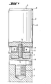
- Die Fig. 1 zeigt einen Kolben, der über einen Adap- ter mit Gewindezapfen mit der Kolbenstange verbunden ist,
- die Fig. 2 einen mittels einer Maschinenschraube am Adapter befestigten Kolben.
- Der Kolben 2 aus gesinterter Oxidkeramik weist im Bereich des Kolbenbodens 3 eine Fase 17 auf, an die sich der Mantel 6 des Kolbens 2 anschließt. Vom Kolbenkopf 4 erstreckt sich ein Sackloch 5 in Richtung des Kolbenbodens 3, das im Grünzustand des Kolbens 2 eingebracht wurde, ohne daß sich nach dem Sinterverfahren eine Bearbeitungsstufe anschloß. Dieses Sackloch 5 wird senkrecht von der Ausnehmung 7 geschnitten, die ebenfalls durch einen Bohrvorgang im Gründzustand des Kolbens 2 eingebracht wurde.
- In dieser Ausnehmung 7 liegt das Gewindestück 8, ein beidseitig angefastes Stück Rundstahl, das mittig mit einer Gewindebohrung 18 versehen wurde. Der Gewindezapfen lo, der Teil des Adapters 9 ist, ist in die Gewindebohrung 18 des Gewindestückes 8 eingedreht und verbindet dadurch den Kolben 2 mit dem Adapter 9. Der Adapter 9 seinerseits ist auf der dem Gewindezapfen lo gegenüberliegenden Seite nit einem Gewindeansatz 11 versehen, auf den die Kolbenstange 1 aufgeschraubt wird. Eine alternative Lösung ist in der Fig. 2 dargestellt, wo statt des Gewindezapfens lo eine Maschinenschraube 12 eingesetzt wird, die die Bohrung 13 im Adapter 9 durchdringt und in das Gewindestück 8 eingreift. An die Bohrung 13 schließt sich eine Aussenkung 14 an, die den Kopf der Maschinenschraube 12 aufnimmt..Der Adapter 9 ist mit einem Ansatz 16 versehen, auf den die als Rohr ausgeführte Kolbenstange 1 aufgeschoben und mittels eines Kerbstiftes 15 befestigt ist.
Claims (3)
Priority Applications (1)
| Application Number | Priority Date | Filing Date | Title |
|---|---|---|---|
| AT83110319T ATE18790T1 (de) | 1982-10-19 | 1983-10-15 | Verdraengerteil einer kolbenpumpe. |
Applications Claiming Priority (2)
| Application Number | Priority Date | Filing Date | Title |
|---|---|---|---|
| DE3238667 | 1982-10-19 | ||
| DE19823238667 DE3238667A1 (de) | 1982-10-19 | 1982-10-19 | Verdraengerteil einer kolbenpumpe |
Publications (2)
| Publication Number | Publication Date |
|---|---|
| EP0108944A1 true EP0108944A1 (de) | 1984-05-23 |
| EP0108944B1 EP0108944B1 (de) | 1986-03-26 |
Family
ID=6176063
Family Applications (1)
| Application Number | Title | Priority Date | Filing Date |
|---|---|---|---|
| EP83110319A Expired EP0108944B1 (de) | 1982-10-19 | 1983-10-15 | Verdrängerteil einer Kolbenpumpe |
Country Status (5)
| Country | Link |
|---|---|
| EP (1) | EP0108944B1 (de) |
| AT (1) | ATE18790T1 (de) |
| DE (2) | DE3238667A1 (de) |
| DK (1) | DK452983A (de) |
| FI (1) | FI73793C (de) |
Cited By (3)
| Publication number | Priority date | Publication date | Assignee | Title |
|---|---|---|---|---|
| WO2014063966A1 (de) * | 2012-10-23 | 2014-05-01 | Robert Bosch Gmbh | Pumpenelement für ein hydraulikaggregat mit einem pumpenkolben |
| IT201800004176A1 (it) * | 2018-04-03 | 2019-10-03 | Pistone in materiale ceramico | |
| IT201900006680A1 (it) * | 2019-05-09 | 2020-11-09 | Annovi Reverberi Spa | Pistone in materiale ceramico |
Families Citing this family (3)
| Publication number | Priority date | Publication date | Assignee | Title |
|---|---|---|---|---|
| US4741254A (en) * | 1986-06-12 | 1988-05-03 | Taylor Julian S | Pump plunger |
| DE3702446A1 (de) * | 1987-01-28 | 1988-08-11 | Kaercher Gmbh & Co Alfred | Hochdruckreinigungsgeraet mit einer taumelscheibenkolbenpumpe |
| DE3914333A1 (de) * | 1989-04-29 | 1990-10-31 | Hoechst Ceram Tec Ag | Pumpenkolben fuer axialkolbenpumpen |
Citations (2)
| Publication number | Priority date | Publication date | Assignee | Title |
|---|---|---|---|---|
| US1195546A (en) * | 1916-08-22 | Pump-piston | ||
| DE2939284A1 (de) * | 1979-09-28 | 1981-04-02 | Feldmühle AG, 4000 Düsseldorf | Verfahren zum herstellen von kolben aus gesinterter oxidkeramik |
-
1982
- 1982-10-19 DE DE19823238667 patent/DE3238667A1/de not_active Withdrawn
-
1983
- 1983-09-30 DK DK452983A patent/DK452983A/da not_active Application Discontinuation
- 1983-10-14 FI FI833740A patent/FI73793C/fi not_active IP Right Cessation
- 1983-10-15 AT AT83110319T patent/ATE18790T1/de active
- 1983-10-15 EP EP83110319A patent/EP0108944B1/de not_active Expired
- 1983-10-15 DE DE8383110319T patent/DE3362709D1/de not_active Expired
Patent Citations (2)
| Publication number | Priority date | Publication date | Assignee | Title |
|---|---|---|---|---|
| US1195546A (en) * | 1916-08-22 | Pump-piston | ||
| DE2939284A1 (de) * | 1979-09-28 | 1981-04-02 | Feldmühle AG, 4000 Düsseldorf | Verfahren zum herstellen von kolben aus gesinterter oxidkeramik |
Cited By (6)
| Publication number | Priority date | Publication date | Assignee | Title |
|---|---|---|---|---|
| WO2014063966A1 (de) * | 2012-10-23 | 2014-05-01 | Robert Bosch Gmbh | Pumpenelement für ein hydraulikaggregat mit einem pumpenkolben |
| CN104755755A (zh) * | 2012-10-23 | 2015-07-01 | 罗伯特·博世有限公司 | 用于液压装置的、带有泵活塞的泵元件 |
| IT201800004176A1 (it) * | 2018-04-03 | 2019-10-03 | Pistone in materiale ceramico | |
| WO2019193437A1 (en) * | 2018-04-03 | 2019-10-10 | Annovi Reverberi S.P.A. | Piston made of ceramic material |
| US11149850B2 (en) | 2018-04-03 | 2021-10-19 | Annovi Reverberi S.P.A. | Piston made of ceramic material |
| IT201900006680A1 (it) * | 2019-05-09 | 2020-11-09 | Annovi Reverberi Spa | Pistone in materiale ceramico |
Also Published As
| Publication number | Publication date |
|---|---|
| FI73793C (fi) | 1987-11-09 |
| FI833740L (fi) | 1984-04-20 |
| FI833740A0 (fi) | 1983-10-14 |
| DE3362709D1 (en) | 1986-04-30 |
| DK452983A (da) | 1984-04-20 |
| DK452983D0 (da) | 1983-09-30 |
| ATE18790T1 (de) | 1986-04-15 |
| EP0108944B1 (de) | 1986-03-26 |
| DE3238667A1 (de) | 1984-04-26 |
| FI73793B (fi) | 1987-07-31 |
Similar Documents
| Publication | Publication Date | Title |
|---|---|---|
| DE2317666C2 (de) | Hydraulikzylinder | |
| EP0108944B1 (de) | Verdrängerteil einer Kolbenpumpe | |
| EP0103906B1 (de) | Verdrängerteil einer Kolbenpumpe | |
| DE10115263A1 (de) | Hydraulikkolben mit geschlossenem Hohlraum und Verfahren zu dessen Herstellung | |
| DE1675337A1 (de) | Schlauchanschluss | |
| DE1259816B (de) | Kolben fuer hydraulische Grubenstempel od. dgl. | |
| EP1410846A1 (de) | Düse zur Erzeugung eines Hochdruckstrahls | |
| DE8229300U1 (de) | Verdraengerteil einer kolbenpumpe | |
| DE1231979B (de) | Arbeitszylinder fuer Druckmittelanlagen | |
| DE10145062B4 (de) | Strahlkopf | |
| DE3208037A1 (de) | Verdraengerteil einer hochdruckpumpe | |
| DE530957C (de) | Schlauchverbindung | |
| DE3305647A1 (de) | Verdraengerteil einer kolbenpumpe | |
| DE3136472C2 (de) | ||
| DE1270330B (de) | Kupplung fuer kraftgetriebene Arbeitswerkzeuge, insbesondere Baumscheren od. dgl. | |
| DE1427720C (de) | ||
| DE1552257C3 (de) | Als Spanndorn oder Spannfutter aus gebildete hydraulische Spannvorrichtung für Werkzeuge oder Werkstucke | |
| DE8513328U1 (de) | Diamantbohrkrone mit Schaftrohr und Rohrgewindeanschluß | |
| DE444638C (de) | Mundstueck fuer Acetylenbrenner | |
| DE1911824A1 (de) | Einspannvorrichtung fuer Werkzeughalter in Werkzeughalteraufnahmen | |
| DE803048C (de) | Werkzeug zum Instandsetzen von Kraftstoffpumpen | |
| AT239619B (de) | Absperrschieber für Hochdruckleitungen | |
| DE3347634A1 (de) | Gebaute walzwerkzeugvorrichtung mit formschluessiger verbindung | |
| DE950998C (de) | Mehrteilige Bohrrohrschelle fuer Grosslochbohrungen | |
| DE3530795A1 (de) | Steckkupplung fuer schlauch- oder rohrleitungen |
Legal Events
| Date | Code | Title | Description |
|---|---|---|---|
| PUAI | Public reference made under article 153(3) epc to a published international application that has entered the european phase |
Free format text: ORIGINAL CODE: 0009012 |
|
| 17P | Request for examination filed |
Effective date: 19831027 |
|
| AK | Designated contracting states |
Designated state(s): AT BE CH DE FR GB IT LI LU NL SE |
|
| ITF | It: translation for a ep patent filed | ||
| GRAA | (expected) grant |
Free format text: ORIGINAL CODE: 0009210 |
|
| AK | Designated contracting states |
Kind code of ref document: B1 Designated state(s): AT BE CH DE FR GB IT LI LU NL SE |
|
| REF | Corresponds to: |
Ref document number: 18790 Country of ref document: AT Date of ref document: 19860415 Kind code of ref document: T |
|
| ET | Fr: translation filed | ||
| REF | Corresponds to: |
Ref document number: 3362709 Country of ref document: DE Date of ref document: 19860430 |
|
| PG25 | Lapsed in a contracting state [announced via postgrant information from national office to epo] |
Ref country code: LU Free format text: LAPSE BECAUSE OF NON-PAYMENT OF DUE FEES Effective date: 19861031 |
|
| PLBE | No opposition filed within time limit |
Free format text: ORIGINAL CODE: 0009261 |
|
| STAA | Information on the status of an ep patent application or granted ep patent |
Free format text: STATUS: NO OPPOSITION FILED WITHIN TIME LIMIT |
|
| 26N | No opposition filed | ||
| PGFP | Annual fee paid to national office [announced via postgrant information from national office to epo] |
Ref country code: LU Payment date: 19890823 Year of fee payment: 7 Ref country code: DE Payment date: 19890823 Year of fee payment: 7 |
|
| PGFP | Annual fee paid to national office [announced via postgrant information from national office to epo] |
Ref country code: FR Payment date: 19890828 Year of fee payment: 7 |
|
| PGFP | Annual fee paid to national office [announced via postgrant information from national office to epo] |
Ref country code: BE Payment date: 19890831 Year of fee payment: 7 |
|
| PGFP | Annual fee paid to national office [announced via postgrant information from national office to epo] |
Ref country code: CH Payment date: 19890905 Year of fee payment: 7 |
|
| PGFP | Annual fee paid to national office [announced via postgrant information from national office to epo] |
Ref country code: GB Payment date: 19890930 Year of fee payment: 7 |
|
| PGFP | Annual fee paid to national office [announced via postgrant information from national office to epo] |
Ref country code: AT Payment date: 19891027 Year of fee payment: 7 |
|
| PGFP | Annual fee paid to national office [announced via postgrant information from national office to epo] |
Ref country code: SE Payment date: 19891030 Year of fee payment: 7 |
|
| ITTA | It: last paid annual fee | ||
| PGFP | Annual fee paid to national office [announced via postgrant information from national office to epo] |
Ref country code: NL Payment date: 19891031 Year of fee payment: 7 |
|
| PG25 | Lapsed in a contracting state [announced via postgrant information from national office to epo] |
Ref country code: GB Effective date: 19901015 Ref country code: AT Effective date: 19901015 |
|
| PG25 | Lapsed in a contracting state [announced via postgrant information from national office to epo] |
Ref country code: SE Effective date: 19901016 |
|
| PG25 | Lapsed in a contracting state [announced via postgrant information from national office to epo] |
Ref country code: LI Effective date: 19901031 Ref country code: CH Effective date: 19901031 Ref country code: BE Effective date: 19901031 |
|
| BERE | Be: lapsed |
Owner name: FELDMUHLE A.G. Effective date: 19901031 |
|
| PG25 | Lapsed in a contracting state [announced via postgrant information from national office to epo] |
Ref country code: NL Effective date: 19910501 |
|
| GBPC | Gb: european patent ceased through non-payment of renewal fee | ||
| NLV4 | Nl: lapsed or anulled due to non-payment of the annual fee | ||
| PG25 | Lapsed in a contracting state [announced via postgrant information from national office to epo] |
Ref country code: FR Effective date: 19910628 |
|
| REG | Reference to a national code |
Ref country code: CH Ref legal event code: PL |
|
| PG25 | Lapsed in a contracting state [announced via postgrant information from national office to epo] |
Ref country code: DE Effective date: 19910702 |
|
| REG | Reference to a national code |
Ref country code: FR Ref legal event code: ST |
|
| EUG | Se: european patent has lapsed |
Ref document number: 83110319.7 Effective date: 19910603 |