EP0108974B1 - Drehmomentbegrenzende Kupplung - Google Patents
Drehmomentbegrenzende Kupplung Download PDFInfo
- Publication number
- EP0108974B1 EP0108974B1 EP83110742A EP83110742A EP0108974B1 EP 0108974 B1 EP0108974 B1 EP 0108974B1 EP 83110742 A EP83110742 A EP 83110742A EP 83110742 A EP83110742 A EP 83110742A EP 0108974 B1 EP0108974 B1 EP 0108974B1
- Authority
- EP
- European Patent Office
- Prior art keywords
- clutch
- spring
- locking mechanism
- notch locking
- notch
- Prior art date
- Legal status (The legal status is an assumption and is not a legal conclusion. Google has not performed a legal analysis and makes no representation as to the accuracy of the status listed.)
- Expired
Links
Images
Classifications
-
- F—MECHANICAL ENGINEERING; LIGHTING; HEATING; WEAPONS; BLASTING
- F16—ENGINEERING ELEMENTS AND UNITS; GENERAL MEASURES FOR PRODUCING AND MAINTAINING EFFECTIVE FUNCTIONING OF MACHINES OR INSTALLATIONS; THERMAL INSULATION IN GENERAL
- F16D—COUPLINGS FOR TRANSMITTING ROTATION; CLUTCHES; BRAKES
- F16D13/00—Friction clutches
- F16D13/22—Friction clutches with axially-movable clutching members
- F16D13/38—Friction clutches with axially-movable clutching members with flat clutching surfaces, e.g. discs
- F16D13/46—Friction clutches with axially-movable clutching members with flat clutching surfaces, e.g. discs in which two axially-movable members, of which one is attached to the driving side and the other to the driven side, are pressed from one side towards an axially-located member
- F16D13/48—Friction clutches with axially-movable clutching members with flat clutching surfaces, e.g. discs in which two axially-movable members, of which one is attached to the driving side and the other to the driven side, are pressed from one side towards an axially-located member with means for increasing the effective force between the actuating sleeve or equivalent member and the pressure member
- F16D13/50—Friction clutches with axially-movable clutching members with flat clutching surfaces, e.g. discs in which two axially-movable members, of which one is attached to the driving side and the other to the driven side, are pressed from one side towards an axially-located member with means for increasing the effective force between the actuating sleeve or equivalent member and the pressure member in which the clutching pressure is produced by springs only
- F16D13/505—Devices located between the flywheel and the driven disc, and biassing the driven disc away from the flywheel towards the disengaged position
-
- F—MECHANICAL ENGINEERING; LIGHTING; HEATING; WEAPONS; BLASTING
- F16—ENGINEERING ELEMENTS AND UNITS; GENERAL MEASURES FOR PRODUCING AND MAINTAINING EFFECTIVE FUNCTIONING OF MACHINES OR INSTALLATIONS; THERMAL INSULATION IN GENERAL
- F16D—COUPLINGS FOR TRANSMITTING ROTATION; CLUTCHES; BRAKES
- F16D43/00—Automatic clutches
- F16D43/02—Automatic clutches actuated entirely mechanically
- F16D43/20—Automatic clutches actuated entirely mechanically controlled by torque, e.g. overload-release clutches, slip-clutches with means by which torque varies the clutching pressure
- F16D43/21—Automatic clutches actuated entirely mechanically controlled by torque, e.g. overload-release clutches, slip-clutches with means by which torque varies the clutching pressure with friction members
- F16D43/213—Automatic clutches actuated entirely mechanically controlled by torque, e.g. overload-release clutches, slip-clutches with means by which torque varies the clutching pressure with friction members with axially applied torque-limiting friction surfaces
- F16D43/215—Automatic clutches actuated entirely mechanically controlled by torque, e.g. overload-release clutches, slip-clutches with means by which torque varies the clutching pressure with friction members with axially applied torque-limiting friction surfaces with flat friction surfaces, e.g. discs
Definitions
- the invention relates to a torque-limiting clutch with two coupling halves which can be disengaged against the force of an axially acting first spring and a locking mechanism arranged in the transmission path and consisting of two parts held in engagement via a spring-loaded latch, the latching mechanism of which can be disengaged and axially adjusted when the limit torque is exceeded Part acts on the adjustable coupling half, the locking device of the locking mechanism being assigned a rising curve, the steepness of which is greater on the first section of the adjustment path than on the section adjoining it.
- Such a coupling is known from US-A-2 587 712.
- the locking mechanism is held in place by a spring. If the torque exceeds a predetermined value, which depends on the spring force and the steepness of the rising curve, the disengageable and axially adjustable part moves in the axial direction against the spring force. This reduces the pressure of the spring on the coupling halves, so that the coupling is released. So that the clutch does not slip before the locking mechanism has responded, the coupling halves should be subjected to the greatest possible spring force.
- the pressurization of the locking mechanism must, however, depend on the transmissible limit torque. In order to be able to meet both requirements at the same time, a compromise must be found for the spring acting simultaneously on the locking mechanism and the coupling halves.
- the invention has for its object to provide a slip clutch with which the setting of the limit torque is possible regardless of the setting of the clutch.
- This object is achieved in that the locking mechanism is acted upon by a second spring alone, which is effective only when the locking mechanism is disengaged on the first section of the adjustment path of the adjustable part and only on the section adjoining the first spring together with the ventilation the clutch causes.
- the coupling half which is connected to the axially adjustable part of the locking mechanism in a rotationally fixed manner, consists of two parts of the other coupling half by means of the force of the spring, between which parts are clamped, of which part is axially immovable and as an abutment for the spring supporting the other part serves.
- the force of a spring or a spring set is used to generate a contact force on both opposite sides of the other coupling half.
- a switching ring is preferably arranged in a non-rotatable and axially displaceable manner on part of the locking mechanism and has a switch which interacts with a nose on the other part of the locking mechanism in such a way that the disengaged other part is closed by the axial adjustment of the switching ring is returned.
- the switch ring has such a recess for receiving the nose on the other part of the locking mechanism that the switching ring in its axially displaced position and the other part are interlocked with one another in the direction of rotation.
- the locking of the switching ring and the other part of the locking mechanism is carried out, for example, before the direct connection of squirrel-cage motors. After the drive has started, the lock is released so that the overload clutch can respond at its limit torque.
- the blocker In order to keep the ratchet release from frictional ice flows largely free, the blocker should be a freely rotatable ball or roller.
- a disc 2 for example in the form of a ring, is embodied.
- a sleeve 5 is mounted on the hub 1 by means of ball bearings 3, 4, but is axially immovable.
- a flange 6 is fixedly connected to the sleeve 5, to which a further flange 8 is fastened in a rotationally fixed but axially movable manner by means of spring-plate plate packs 7 arranged in a ring.
- the flange 8 and the disc 2 form parts of a locking mechanism.
- Several such locks 9 are provided on the circumference of the flange 8. Each of these balls is assigned a recess 11 in the disc 2 as a rest.
- the lock 9 is held in this detent 11 by spring force.
- the spring force is applied by a spring 12. which is supported on an adjusting ring 13 and pressurizes the flange 8 in the direction of the disk 2.
- the spring force of this spring 12 can be adjusted by adjusting screws 14 arranged in the sleeve 5 and acting on the adjusting ring 13.
- the mutual rotation of the two parts 2, 3 which is possible after the locking mechanism has been triggered is limited by a stop which is formed by a bolt 16 which engages in a recess 15 in the flange 8 with play.
- An adjusting ring 17 with a switch 18 is arranged on the flange 8 in a rotationally fixed but axially displaceable manner and a nose 19 is assigned to it on the disk 2.
- the switch 18 has such an opening that it detects the maximum possible rotation of the two parts 2, 8.
- the fork-shaped switch 18 has at its base a recess 18a which is adapted to the shape of the nose 19. If the adjusting ring 17 is axially displaced so far that the nose 19 is in the recess 18a, then the adjusting ring 2 and the flange 8 are positively locked together in the direction of rotation, so that the catch cannot disengage.
- the flange 6 carries a friction clutch lining 21 and forms part of a clutch half.
- the other part of this coupling half is formed by a flange 22 which also carries a clutch lining 23.
- This last-mentioned part 22 is pressurized by a coil spring 24 which is held on the other part 6 of the same coupling half by means of a screw bolt 25.
- a disc 26 is arranged as the other coupling half, which is made in one piece with a hub-shaped output part 27.
- This driven part 27 is rotatable via ball bearings 28, 29 on a hub 30 integrally connected to the flange 6 and is axially displaceable to a limited extent.
- the axial mobility is limited by stops 31, 32, 33 on the hubs 27, 30.
- a plate spring 34 between the two bearings 28, 29 pressurizes the hub 27 in the opposite direction to the pressure direction of the spring 24.
- the blocker can also be designed as a roller, as shown in FIGS. 3 and 4.
- the hub 1 coupled to the drive rotates with the disk 2 with respect to the flange 8.
- the flange 8 On the first section a of a rising curve formed in the disk 2 (cf. FIG. 7), the flange 8 only needs to be displaced against the force of the spring 12 to be because a pot 35 attached to the flange 8 has not yet come into contact with a collar 37 with its edge 36.
- the force of the spring 24 In the second section b, however, the force of the spring 24 must also be overcome. So that no larger forces are necessary, the slope in the second section b is chosen to be smaller.
- the clutch 6 is ventilated in this second section b. 21 to 23, 26. As soon as the clutch 6, 21 to 23, 26 is released, the hub 1 can rotate freely with respect to the abrasion part 27.
- the twisting of the Parts 2, 8 of the locking mechanism after ventilation is limited by the stop 15, 16.
- the adjusting ring 17 is displaced axially until the nose 19 is located in the recess 18a. Since the side flanks of the recess 18a are perpendicular to the direction of the effective torque, the torque is transmitted from the flange 2 via the nose 19 and the recess 18a to the flange 8. The power flow that otherwise takes place via the rest 9 is thus diverted, so that the locking mechanism cannot respond when the limit torque is exceeded.
- the clutch responds very quickly in the event of an overload. Since the locking mechanism acts as a release element, but the clutch is a friction or spur-toothed clutch, which is fully uncoupled after release, only slight frictional forces have to be overcome when released and after release, the overload clutch runs as long as desired without causing wear or any other type Load on the clutch is connected.
- the clutch can also be switched on quickly and easily from the outside.
Landscapes
- Engineering & Computer Science (AREA)
- General Engineering & Computer Science (AREA)
- Mechanical Engineering (AREA)
- Mechanical Operated Clutches (AREA)
Description
- Die Erfindung bezieht sich auf eine drehmomentbegrenzende Kupplung mit zwei gegen die Kraft einer axial wirkenden ersten Feder außer Eingriff bringbaren Kupplungsnälften und einem im Übertragungsweg angeordneten, aus zwei über eine federbelastete Rast in Eingriff gehaltenen Teilen bestehenden Rastgesperre, dessen bei Überschreiten des Grenzmomentes ausrastbar und axial verstellbarer Teil auf die verstellbare Kupplungshälfte einwirkt, wobei dem Sperrer des Rastgesperres eine Steigkurve zugeordnet ist, deren Steilheit auf dem ersten Abschnitt des Verstellweges größer als auf dem sich daran anschließenden Abschnitt ist.
- Eine derartige Kupplung ist aus der US-A-2 587 712 bekannt. Das Rastgesperre wird durch eine Feder eingerastet gehalten. Wenn das Drehmoment einen vorgegebenen Wert übersteigt, der von der Federkraft und der Steilheit der Steigkurve abhängt, bewegt sich das ausrastbare und axial verstellbare Teil in axialer Richtung gegen die Federkraft. Dadurch wird der Druck der Feder auf die Kupplungshälften verringert, so daß die Kupplung gelüftet wird. Damit die Kupplung nicht durchrutscht, bevor das Rastgesperre angesprochen hat, sollten die Kupplungshälften mit einer möglichst großen Federkraft beaufschlagt werden. Die Druckbeaufschlagung des Rastgesperres jedoch muß sich nach dem übertragbaren Grenzmoment richten. Um beide Forderungen gleichzeitig erfüllen zu können, muß ein Kompromiß für die das Rastgesperre und die Kupplungshälften gleichzeitig beaufschlagende Feder gefunden werden. Eine optimale Einstellung des Rastgesperres und eine optimale Einstellung der Kupplungshälften ist deshalb nicht gleichzeitig möglich. Aus der DE-U-7 243 689 ist eine ähnliche drehmomentbegrenzende Kupplung bekannt. Bei ihr weist jedoch das Rastgesperre keine Steigkurve mit unterschiedlichen Steigungen auf. Diese Kupplung hat die gleichen Nachteile wie die eingangs genannte bekannte Kupplung.
- Der Erfindung liegt die Aufgabe zugrunde, eine Rutschkupplung zu schaffen, mit der die Einstellung des Grenzmomentes ohne Rücksicht auf die Einstellung der Kupplung möglich ist.
- Diese Aufgabe wird erfindungsgemäß dadurch gelöst, daß das Rastgesperre alleine von einer zweiten Feder beaufschlagt ist, die beim Ausrasten des Rastgesperres auf dem ersten Abschnitt des Verstellweges des verstellbaren Teiles allein wirksam ist und erst auf dem sich daran anschließenden Abschnitt mit der ersten Feder zusammen das Lüften der Kupplung bewirkt.
- Wegen des Einsatzes von individuellen Federn für die Kupplung und das Rastgesperre wird erreicht, daß die Einstellung des Grenzmomentes völlig unabhängig von der Einstellung der Kupplung ist. Erst wenn das Rastgesperre angesprochen hat, d. h., wenn die Rast den ersten Abschnitt des Verstellweges gegen die wirksame Kraft der ersten Feder überwunden hat, wird die zweite Feder wirksam. Durch die Wahl der Neigung des zweiten Abschnittes der Steigkurve ist es möglich, das erforderliche Moment für das Lösen der Kupplung zu bestimmen. Im Grenzfall ist es möglich, die Neigung auf dem zweiten Abschnitt so flach zu wählen, daß trotz der beiaen gleichzeitig wirksamen Federn das Moment für die weitere Verstellung bis zum Lösen der Kupplung kleiner als auf dem ersten Abschnitt während des Ausrastens ist.
- Nach einer ersten Ausgestaltung der Erfindung besteht die mit dem axial verstellbaren Teil des Rastgesperres drehfest verbundene Kupplungshälfte aus zwei die andere Kupplungshälfte mittels der Kraft der Feder zwischen sich einklemmenden Teilen, von denen ein Teil axial unverschieblich ist und als Widerlager für die das andere Teil abstützende Feder dient. Bei dieser Ausgestaltung wird, wie an sich bekannt, die Kraft einer Feder bzw. eines Federsatzes ausgenutzt, um eine Anpreßkraft an beiden gegenüberliegenden Seiten der anderen Kupplungshälfte zu erzeugen.
- Damit gewährleistet ist, daß bei nicht gelüfteter Kupplung die andere Kupplungshälfte mit beiden gegenüberliegenden Seiten an der einen Kupplungshälfte anliegt und bei gelüfteter Bremse die andere Kupplungshälfte auch von dem axial feststehenden Teil der einen Kupplungshälfte abgehoben wird, ist vorgesehen, daß auf die andere Kupplungshälfte eine weitere Feder in Lüftungsrichtung einwirkt, deren Federkraft kleiner als die Kraft der in Gegenrichtung wirkenden Feder der einen Kupplungshälfte ist. Darüber hinaus sollte die axiale Beweglichkeit der anderen Kupplungshälfte durch einen Anschlag auf ein Spiel begrenzt sein, das kleiner als das gesamte Lüftungsspiel zwischen den beiden Teilen der einen Kupphälfte ist. Dadurch wird sichergestellt, daß bei gelüfteter Kupplung die andere Kupplungshälfte mit keiner ihrer beiden gegenüberliegenden Seiten schleift.
- Da das Rastgesperre und die Kupplung hintereinandergeschaltet im Kraftübertragungsweg zwischen Antrieb und Abtrieb liegen und das Rastgesperre nur als Auslöseorgan der Kupplung wirkt, ist es nicht erforderlich, daß die beiden Teile des Rastgesperres sich nach Ansprechen des Rastgesperres frei gegeneinander verdrehen können, vielmehr ist vorzugsweise der gegenseitige Verdrehwinkel der beiden Teile des Rastgesperres durch Anschläge begrenzt. Bei dieser Ausgestaltung braucht der eine Teil nur geringfügig zurückgedreht zu werden, um wieder die Raststellung einzunehmen. Für das Einschalten des Rastgesperres ist vorzugsweise ein Schaltring unverdrehbar und axial verschieblich auf einem Teil des Rastgesperres angeordnet und weist eine Weiche auf, die mit einer Nase am anderen Teil des Rastgesperres derart zusammenwirkt, daß das ausgerastete andere Teil durch Axialverstellung des Schaltringes in die Raststellung zurückgeführt wird.
- Um unter bestimmten Betriebsbedingungen, bei denen sehr hohe Drehmomente auftreten können, z. B. bei der Direkteinschaltung von Kurzschlußläufermotoren, ein Ansprechen der für geringere Drehmomente eingestellten Kupplung zu verhindern, ist nach einer Ausgestaltung der Erfindung vorgesehen, daß die Weiche des Schaltringes eine solche Ausnehmung für die Aufnahme der Nase am anderen Teil des Rastgesperres hat, daß der Schaltring in seiner axial verschobenen Stellung und das andere Teil in Drehrichtung formschlüssig miteinander verriegelt sind.
- Mit diesen ausgestaltenden Merkmalen wird beispielsweise vor der Direkteinschaltung von Kurzschlußläufermotoren die Verriegelung des Schaltringes und des anderen Teils des Rastgesperres vorgenommen. Nach dem Anlauf des Antriebes wird die Verriegelung wieder aufgehoben, so daß die Überlastkupplung bei ihrem Grenzmoment ansprechen kann.
- Um das Auslösen des Rastgesperres von Reibungseiflüssen weitgehend frei zu halten, sollte der Sperrer eine frei drehbar gelagerte Kugel oder Rolle sein.
- Im folgenden wird die Erfindung anhand einer ein Ausführungsbeispiel darstellenden Zeichnung näher erläutert.
- Im einzelnen zeigen
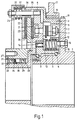
- Figur 1 eine drehmomentbegrenzende Kupplung im halben Axialschnitt,
- Figur 2 einen Axialschnitt der Kupplung gemäß Fig. 1 im Bereich des Rastgesperres,
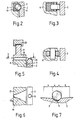
- Figuren 3 und 4 alternative Ausführungen des Rastgesperres im Axialschnitt,
- Figur 5 eine Einschaltvorrichtung für das Rastgesperre im Axialschnitt,
- Figur 6 die Einschaltvorrichtung gemäß Fig. 5 im Schnitt nach der Linie I-I und
- Figur 7 einen Teil des Rastgesperres gemäß Fig. 2 im Schnitt nach der Linie II-II.
- Einstückig mit einer Nabe 1, die an einen Antrieb kuppelbar ist, ist eine beispielsweise als Ring ausgebildete Scheibe 2 ausgeführt. Auf der Nabe 1 ist mittels Kugellager 3, 4 drehbar, aber axial unverschieblich, eine Hülse 5 gelagert. Mit der Hülse 5 ist ein Flansch 6 fest verbunden, an dem über kranzförmig angeordnete Federlaschen-Lamellenpakete 7 ein weiterer Flansch 8 drehfest aber axial beweglich befestigt ist.
- Der Flansch 8 und die Scheibe 2 bilden Teile eines Rastgesperres. Zu diesem Rastgesperre gehört als Sperrer eine Kugel 9, die in einer Kunststofflagerung 10 in der Scheibe 2 gehalten ist. Mehrere solcher Sperrer 9 sind am Umfang des Flansches 8 vorgesehen. Jeder diese Kugeln ist in der Scheibe 2 als Rast eine Vertiefung 11 zugeordnet. Durch Federkraft wird der Sperrer 9 in dieser Rast 11 gehalten. Die Federkraft wird von einer Feder 12 aufgebracht. die sich an einem Stellring 13 abstützt und den Flansch 8 in Richtung der Scheibe 2 druckbeaufschlagt. Die Federkraft dieser Feder 12 läßt sich durch in der Hülse 5 angeordnete, auf den Stellring 13 einwirkende Stellschrauben 14 einstellen. Die nach Auslösen des Rastgesperres mögliche gegenseitige Verdrehung der beiden Teile 2, 3 wird durch eine Anschlag begrenzt, der von einer in eine Ausnehmung 15 des Flansches 8 mit Spiel eingreifenden Bolzens 16 gebildet wird.
- Auf dem Flansch 8 ist drehfest, aber axial verschlieblich, ein Stellring 17 mit einer Weiche 18 angeordnet, der auf der Scheibe 2 eine Nase 19 zugeordnet ist. Die Weiche 18 hat eine solche Öffnung, daß sie den maximal möglichen Verdrehweg der beiden Teile 2, 8 erfaßt. Mittels einer den Stellring 17 erfassenden Gabel 20 läßt sich der Stellring 17 bei jeder Drehstellung axial verschieben. Die gabelförmige Weiche 18 hat an ihrem Grund eine Ausnehmung 18a, die der Form der Nase 19 angepaßt ist. Ist der Stellring 17 axial so weit verschoben, daß die Nase 19 in der Ausnehmung 18a sich befindet, dann sind der Stellring 2 und der Flansch 8 in Drehrichtung formschlüssig miteinander vedrriegelt, so daß die Rast nicht ausrasten kann.
- Der Flansch 6 trägt einen Reibungskupplungsbelag 21 und bildet einen Teil einer Kupplungshälfte. Der Andere Teil dieser Kupplungshälfte wird von einem Flansch 22 gebildet, der ebenfalls einen Kupplungsbelag 23 trägt. Dieser letzt genannte Teil 22 wird von einer Schraubenfeder 24, die mittels eines Schraubenbolzens 25 an dem anderen Teil 6 derselben Kupplungshälfte gehalten ist, druckbeaufschlagt. Zwischen den beiden Teilen 6, 21, 22, 23 ist als andere Kupplungshälfte eine Scheibe 26 angeordnet, die einstückig mit einem nabenförmigen Abtriebsteil 27 ausgeführt ist. Dieses Abtriebsteil 27 ist über Kugellager 28, 29 auf einer einstückig mit dem Flansch 6 verbundenen Nabe 30 drehbar und beschränkt axial verschieblich gelagert. Die axiale Beweglichkeit wird durch Anschläge 31, 32, 33 auf den Naben 27, 30 begrenzt. Eine Tellerfeder 34 zwischen den beiden Lagern 28, 29 druckbeaufschlagt die Nabe 27 in entgegengesetzter Richtung zur Druckrichtung der Feder 24.
- An Stelle der Ausbildung des Sperrers als Kugel 9 kann der Sperrer auch als Rolle, wie in Fig. 3 und 4 dargestellt ist, ausgeführt sein.
- Die beschriebene drehmomentbegrenzende Kupplung arbeitet auf folgende Art und Weise :
- Im Überlastfall verdreht sich die am Antrieb gekuppelte Nabe 1 mit der Scheibe 2 gegenüber dem Flansch 8. Auf dem ersten Abschnitt a einer in der Scheibe 2 ausgebildeten Steigkurve (vgl. Fig. 7) braucht der Flansch 8 nur gegen die Kraft der Feder 12 verschoben zu werden, weil ein am Flansch 8 angesetzter Topf 35 mit seinem Rand 36 noch nicht zur Anlage an einem Kragen 37 gekommen ist. Im zweiten Abschnitt b dagegen muß auch die Kraft der Feder 24 überwunden werden. Damit keine größeren Kräfte nötig sind, ist die Steilheit im zweiten Abschnitt b kleiner gewählt. Auf diesem zweiten Abschnitt b erfolgt die Lüftung der Kupplung 6. 21 bis 23, 26. Sobald die Kupplung 6, 21 bis 23, 26 gelüftet ist, kann sich die Nabe 1 frei gegenüber dem Abriebsteil 27 drehen. Die Verdrehung der Teile 2, 8 des Rastgesperres nach erfolgter Lüftung wird begrenzt durch den Anschlag 15, 16.
- Sobald die Kupplung 6, 21 bis 23, 26 gelüftet wird, wird nicht nur der Flansch 22 mit seinem Belag 23 von der Scheibe 26 abgehoben, sondern es wird auch die Scheibe 26 vom Belag 21 des anderen Flansches 6 der Kupplungshälfte abgehoben, und zwar dadurch, daß die Tellerfeder 34 die Nabe 27 zusammen mit der Scheibe 26 bis zur Anlage des Lagers 28 am Anschlag 31 verschiebt.
- Soll nun die Kupplung wieder eingeschaltet werden, dann braucht lediglich der Stellring 17 axial verschoben zu werden. Die Nase 19 wird von der Weiche 18 erfaßt und bei weiterer Verschiebung wird der Teil 2 gegenüber dem Teil 8 zurückgedreht, so daß der Sperrer 9 wieder einrasten kann. Die damit verbundene Axialverschiebung des Flansches 8 unter der Wirkung der Schraubenfeder 12 hat zur Folge, daß auch die Kupplung 6, 20 bis 23, 26 unter der Wirkung der Schraubenfeder 24 wieder eingeschaltet wird.
- Sofern ein Ansprechen der Kupplung bei Überschreiten des Grenzmomentes nicht gewünscht wird, wird der Stellring 17 axial so weit verschoben, bis daß die Nase 19 in der Ausnehmung 18a sich befindet. Da die Seitenflanken der Ausnehmung 18a senkrecht zur Richtung des wirksamen Drehmomentes liegen, wird das Drehmoment von dem Flansch 2 über die Nase 19 und die Ausnehmung 18a auf den Flansch 8 übertagen. Der sonst über die Rast 9 erfolgende Kraftfluß wird damit umgeleitet, so daß das Rastgesperre bei Überschreiten des Grenzmomentes nicht ansprechen kann.
- Die mit der Erfindung erzielten Vorteile bestehen darin, daß im Überlastfall die Kupplung sehr schnell anspricht. Da das Rastgesperre als Auslöseorgan wirkt, die Kupplung aber eine Reibungs-oder stirnverzahnte Kupplung ist, die nach Auslösen voll entkuppelt ist, sind beim Auslösen nur geringe Reibungskräfte zu überwinden und nach Auslösen läuft die Überlastkupplung beliebig lange, ohne daß damit ein Verschleiß oder eine andersartige Belastung der Kupplung verbunden ist. Auch läßt sich die Kupplung von außen leicht und schnell wieder einschalten.
Claims (9)
Applications Claiming Priority (3)
| Application Number | Priority Date | Filing Date | Title |
|---|---|---|---|
| DE3241914 | 1982-11-12 | ||
| DE3241914A DE3241914C2 (de) | 1982-11-12 | 1982-11-12 | Mechanisch bei Überlast ausrückbare Reibscheiben-Kupplung |
| DE8231823U DE8231823U1 (de) | 1982-11-12 | 1982-11-12 | Mechanisch bei Überlast ausrückbare Reibscheiben-Kupplung |
Publications (2)
| Publication Number | Publication Date |
|---|---|
| EP0108974A1 EP0108974A1 (de) | 1984-05-23 |
| EP0108974B1 true EP0108974B1 (de) | 1986-12-03 |
Family
ID=27623640
Family Applications (1)
| Application Number | Title | Priority Date | Filing Date |
|---|---|---|---|
| EP83110742A Expired EP0108974B1 (de) | 1982-11-12 | 1983-10-27 | Drehmomentbegrenzende Kupplung |
Country Status (2)
| Country | Link |
|---|---|
| EP (1) | EP0108974B1 (de) |
| DE (1) | DE8231823U1 (de) |
Families Citing this family (3)
| Publication number | Priority date | Publication date | Assignee | Title |
|---|---|---|---|---|
| DE102007004703B4 (de) * | 2007-01-31 | 2015-12-31 | Desch Antriebstechnik Gmbh & Co. Kg | Sicherheitskupplung |
| CN102900789B (zh) * | 2012-10-09 | 2015-06-17 | 常州南车铁马科技实业有限公司 | 摩擦式限矩离合器 |
| CN105114482A (zh) * | 2015-09-25 | 2015-12-02 | 力博重工科技股份有限公司 | 矿用新型离合装置 |
Family Cites Families (6)
| Publication number | Priority date | Publication date | Assignee | Title |
|---|---|---|---|---|
| DE892097C (de) * | 1953-08-20 | Siemens-Schuckerfwerke Aktiengesellschaft, Berlin und Erlangen | Selbsttätig bei Überschreiten 'eines Grenzdrehmomenrs ausrückende Kupplung, insbesondere für elektromotorische Stellantriebe | |
| DE7243689U (de) * | 1973-04-26 | Teldix Gmbh | Sicherheitsrutschkupplung | |
| GB358617A (en) * | 1930-07-22 | 1931-10-15 | Andrew Henderson | Improvements in and relating to couplings, clutches and the like |
| US2587712A (en) * | 1945-09-29 | 1952-03-04 | Adiel Y Dodge | Overload released clutch |
| JPS5117386Y2 (de) * | 1971-06-22 | 1976-05-11 | ||
| JPS5214818B2 (de) * | 1972-03-10 | 1977-04-25 |
-
1982
- 1982-11-12 DE DE8231823U patent/DE8231823U1/de not_active Expired
-
1983
- 1983-10-27 EP EP83110742A patent/EP0108974B1/de not_active Expired
Also Published As
| Publication number | Publication date |
|---|---|
| EP0108974A1 (de) | 1984-05-23 |
| DE8231823U1 (de) | 1986-01-23 |
Similar Documents
| Publication | Publication Date | Title |
|---|---|---|
| EP0195853B1 (de) | Kupplung für kraftgetriebene Schraubwerkzeuge | |
| DE19857199B4 (de) | Automatisch nachstellbare Reibungskupplung | |
| EP0401548B1 (de) | Schraubwerkzeugmaschine | |
| DE3445343A1 (de) | Antriebskraftuebertragungsvorrichtung | |
| DE4336445C2 (de) | Stelleinrichtung mit einer Sicherungseinrichtung | |
| DE2827948B2 (de) | Ausrückkupplung | |
| DE3241914C2 (de) | Mechanisch bei Überlast ausrückbare Reibscheiben-Kupplung | |
| DE3015423A1 (de) | Motorisch beschriebener abschaltschrauber | |
| DE20112976U1 (de) | Schwenkbeschlag | |
| EP0756099B1 (de) | Kupplung | |
| DE2243333A1 (de) | Drehmomentbegrenzer | |
| WO2017016996A1 (de) | Sitzversteller mit zusatzverriegelung | |
| EP0108974B1 (de) | Drehmomentbegrenzende Kupplung | |
| CH650617A5 (de) | Rastenwerk an einem schalter mit mehreren schaltstellungen. | |
| DE19715269C1 (de) | Kupplung zur Drehmomentbegrenzung | |
| DE2739489B2 (de) | Ausrückkupplung | |
| DE4026213C2 (de) | ||
| DE3023541C1 (de) | UEberlastkupplung | |
| EP0572802B1 (de) | Nachstellvorrichtung für Fahrzeugbremsen | |
| DE3046111C2 (de) | ||
| DE19651633C1 (de) | Druckplattenbaugruppe für eine Kraftfahrzeug-Reibungskupplung mit automatischem Spielausgleich | |
| DE102007057865A1 (de) | Drehmomentbegrenzungskupplung | |
| DE3442083C2 (de) | ||
| DE1175039B (de) | Mechanisch schaltbare Sicherheitsreibungskupplung | |
| AT241282B (de) | Selbsttätig wirkende, durch Fliehkraft betätigte Kupplung für Kraftfahrzeuge |
Legal Events
| Date | Code | Title | Description |
|---|---|---|---|
| PUAI | Public reference made under article 153(3) epc to a published international application that has entered the european phase |
Free format text: ORIGINAL CODE: 0009012 |
|
| AK | Designated contracting states |
Designated state(s): CH DE FR GB IT LI SE |
|
| 17P | Request for examination filed |
Effective date: 19840627 |
|
| ITF | It: translation for a ep patent filed | ||
| GRAA | (expected) grant |
Free format text: ORIGINAL CODE: 0009210 |
|
| AK | Designated contracting states |
Kind code of ref document: B1 Designated state(s): CH DE FR GB IT LI SE |
|
| REF | Corresponds to: |
Ref document number: 3368105 Country of ref document: DE Date of ref document: 19870115 |
|
| ET | Fr: translation filed | ||
| PLBE | No opposition filed within time limit |
Free format text: ORIGINAL CODE: 0009261 |
|
| STAA | Information on the status of an ep patent application or granted ep patent |
Free format text: STATUS: NO OPPOSITION FILED WITHIN TIME LIMIT |
|
| 26N | No opposition filed | ||
| PGFP | Annual fee paid to national office [announced via postgrant information from national office to epo] |
Ref country code: GB Payment date: 19900921 Year of fee payment: 8 |
|
| PGFP | Annual fee paid to national office [announced via postgrant information from national office to epo] |
Ref country code: FR Payment date: 19900925 Year of fee payment: 8 |
|
| PGFP | Annual fee paid to national office [announced via postgrant information from national office to epo] |
Ref country code: CH Payment date: 19900926 Year of fee payment: 8 |
|
| PGFP | Annual fee paid to national office [announced via postgrant information from national office to epo] |
Ref country code: SE Payment date: 19901003 Year of fee payment: 8 |
|
| ITTA | It: last paid annual fee | ||
| PGFP | Annual fee paid to national office [announced via postgrant information from national office to epo] |
Ref country code: DE Payment date: 19901203 Year of fee payment: 8 |
|
| PG25 | Lapsed in a contracting state [announced via postgrant information from national office to epo] |
Ref country code: GB Effective date: 19911027 |
|
| PG25 | Lapsed in a contracting state [announced via postgrant information from national office to epo] |
Ref country code: SE Effective date: 19911028 |
|
| PG25 | Lapsed in a contracting state [announced via postgrant information from national office to epo] |
Ref country code: LI Effective date: 19911031 Ref country code: CH Effective date: 19911031 |
|
| GBPC | Gb: european patent ceased through non-payment of renewal fee | ||
| PG25 | Lapsed in a contracting state [announced via postgrant information from national office to epo] |
Ref country code: FR Effective date: 19920630 |
|
| REG | Reference to a national code |
Ref country code: CH Ref legal event code: PL |
|
| PG25 | Lapsed in a contracting state [announced via postgrant information from national office to epo] |
Ref country code: DE Effective date: 19920701 |
|
| REG | Reference to a national code |
Ref country code: FR Ref legal event code: ST |
|
| EUG | Se: european patent has lapsed |
Ref document number: 83110742.0 Effective date: 19920510 |