EP0108988B1 - Verfahren und Einrichtung zum Lagern von Tabak oder dergleichen in hohen Stapeln und zu seiner Entladung - Google Patents
Verfahren und Einrichtung zum Lagern von Tabak oder dergleichen in hohen Stapeln und zu seiner Entladung Download PDFInfo
- Publication number
- EP0108988B1 EP0108988B1 EP83110854A EP83110854A EP0108988B1 EP 0108988 B1 EP0108988 B1 EP 0108988B1 EP 83110854 A EP83110854 A EP 83110854A EP 83110854 A EP83110854 A EP 83110854A EP 0108988 B1 EP0108988 B1 EP 0108988B1
- Authority
- EP
- European Patent Office
- Prior art keywords
- tobacco
- conveyor
- chambers
- discharging
- chamber
- Prior art date
- Legal status (The legal status is an assumption and is not a legal conclusion. Google has not performed a legal analysis and makes no representation as to the accuracy of the status listed.)
- Expired
Links
- 241000208125 Nicotiana Species 0.000 title claims description 113
- 235000002637 Nicotiana tabacum Nutrition 0.000 title claims description 113
- 238000007599 discharging Methods 0.000 title claims description 34
- 238000000034 method Methods 0.000 title claims description 7
- 238000005192 partition Methods 0.000 claims description 15
- 230000006835 compression Effects 0.000 claims description 3
- 238000007906 compression Methods 0.000 claims description 3
- 230000002411 adverse Effects 0.000 description 3
- 230000000694 effects Effects 0.000 description 3
- 238000009434 installation Methods 0.000 description 3
- 241000233457 Mesophyllum Species 0.000 description 1
- 230000002776 aggregation Effects 0.000 description 1
- 238000004220 aggregation Methods 0.000 description 1
- 230000001771 impaired effect Effects 0.000 description 1
- 238000002156 mixing Methods 0.000 description 1
- 230000000391 smoking effect Effects 0.000 description 1
Images


Classifications
-
- A—HUMAN NECESSITIES
- A24—TOBACCO; CIGARS; CIGARETTES; SIMULATED SMOKING DEVICES; SMOKERS' REQUISITES
- A24B—MANUFACTURE OR PREPARATION OF TOBACCO FOR SMOKING OR CHEWING; TOBACCO; SNUFF
- A24B3/00—Preparing tobacco in the factory
- A24B3/08—Blending tobacco
-
- A—HUMAN NECESSITIES
- A24—TOBACCO; CIGARS; CIGARETTES; SIMULATED SMOKING DEVICES; SMOKERS' REQUISITES
- A24B—MANUFACTURE OR PREPARATION OF TOBACCO FOR SMOKING OR CHEWING; TOBACCO; SNUFF
- A24B3/00—Preparing tobacco in the factory
-
- A—HUMAN NECESSITIES
- A24—TOBACCO; CIGARS; CIGARETTES; SIMULATED SMOKING DEVICES; SMOKERS' REQUISITES
- A24B—MANUFACTURE OR PREPARATION OF TOBACCO FOR SMOKING OR CHEWING; TOBACCO; SNUFF
- A24B3/00—Preparing tobacco in the factory
- A24B3/06—Loosening tobacco leaves or cut tobacco
Definitions
- This invention relates to a method and apparatus for storing tobacco or the like in a high stack and discharging the same according to the preamble of claims 1 and 3.
- the upper limit of the stack height is usually about 1.2 m (1.5 m max) in case of cut tobacco leaves free from stem and 0.5 m (0.7 m max) in case of shredded or cut tobacco.
- a plurality of storage conveyors are stacked one above another.
- tobacco is usually stacked in the storing conveyor for the purpose of blending, and it is stacked to varying heights unless the stacking is done using a stacking conveyor which is reciprocable over the entire length of the storing conveyor. Therefore, it is difficult to permit the stored tobacco to be discharged at a constant rate.
- each chamber being designed like a parallelepiped block (CH-A-592 556).
- the main extension of the chamber is horizontal and perpendicular to a discharging conveyor common to all chambers of the row.
- a charging conveyor can be reciprocated on top of each chamber for charging it with layers of tobacco.
- the bottom of each chamber is constituted by another endless transport means which is adapted to transport the tobacco within the chamber horizontally to a discharging end at one side of the chamber. Adjacent this end side mixers are provided for separating cross sections of the tobacco being transported to them by the moving bottom. The separated cross sections of the tobacco may fall on the common discharging conveyor where the tobacco may spread out. Possibly in order for avoiding the disadvantages of a too high stack the large horizontal extension of the storage chambers is provided. However, this requires the mentioned large installation area and complicated discharging means.
- Another prior art apparatus for storing tobacco comprises a plurality of chambers arranged in a row above a discharging conveyor which chambers have a foot plate hinged to one of the sidewalls of the chambers at a bottom end thereof to open and close on a downstream side of the sidewall (DE-C-882 665).
- These chambers are tapered to their bottom ends. Consequently two neighboured chambers are separated by an intermediate space at least at their bottom ends.
- the intermediate spaces are provided for allowing batches or aggregations of tobacco falling off the chambers on the discharging conveyor to be spread out thereon.
- the chambers are firstly charged with layers of tobacco. As soon as sufficient layers are contained in the chambers the foot plates of the chambers are opened, preferably simultaneously.
- the tobacco layers are falling off the chambers on the discharging conveyor and accumulate in batches thereon.
- the conveyor then moves the batches slowly along persons who are spreading out the batches on the conveyor.
- the foot plates may be opened again thus positioning tobacco batches in regular distances on the discharging conveyor.
- This prior art apparatus does not control the stack level and therefore the capacity of the chambers may not be used effectively or-if too high stacks happen-the quality of the tobacco may be impaired. Further, manpower is necessary to reach the desired spreading of the tobacco batches accumulated on the conveyor belt.
- the gist of the invention lies in that the tobacco leaves which have been kept horizontal in the storage chambers are discharged onto the conveyor in the form to a continuous tobacco layer containing tobacco laeves vertically oriented which can be easily unravelled by a rake at a head section of the conveyor into separate piece of tobacco leaves.
- FIG. 1 there is shown the apparatus according to the invention which com- orises a box-like storage section 1.
- a conveyor 2 for charging is provided over the storage section 1.
- a horizontal conveyor 3 for discharging is provided beneath the storage section 1.
- the storage section 1 has opposite side walls 4, and its interior space is divided by partition walls 5 into a plurality of vertically elongate storage chambers 6 arranged juxtaposed in a row extending in the direction of progress of the discharging conveyor 3.
- the distance between adjacent partition walls 5 is selected depending on the character of tobacco.
- the horizontal conveyor 3 runs in a predetermined direction.
- each chamber 6 is defined by a plurality of side walls which include a first side wall extending perpendicular to said predetermined direction and a pair of second side walls extending on a downstream side of said first side wall parallel to said predetermined direction.
- a floor plate 8 is hinged to said first side wall at a bottom end thereof to open and close on a downstream side of the first sidewall.
- the horizontal conveyor 3 is spaced apart from the each chamber 6 by a distance substantially equal to the horizontal size of each second sidewalls, said each second side wall having at least one transparent window therein.
- a pair of transparent tobacco support plates 11 is erected substantially in parallel to the second sidewalls between the chambers 6 and the conveyor 3.
- the thickness of the tobacco layer on the discharging conveyor 3 is substantially equal to the distance noted. The distance is thus usually roughly 0.6 m and up to approximately 0.8 m.
- the individual partition walls 5 may be inclined from the vertical depending on the character of tobacco.
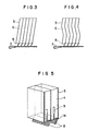
- the inclination angle is set in a range up to about 70 degrees from the horizontal as shown in Fig. 3.
- zig-zag partition walls as shown in Fig. 4 may be provided within the inclination angle range noted above.
- the side walls 4 are usually disposed upright as shown in Fig. 2. However, they may be disposed such that they flare slightly toward the bottom to allow smooth discharge of tobacco from the bottom of the storage chamber.
- the height of the storage chamber is restricted by the height of the ceiling of the factory, and in the instant embodiment it may be set to 3 to 6 m. However, it may be as high as possible otherwise.
- the side walls 4 have opposed transparent windows 15 formed in their upper portions to see therethrough. Detectors (for instance photoelectric detectors) 7 for detecting the height of tobacco loaded in the storage chambers 6 are provided at the front and rear ends of the loading conveyor 2.
- Each storage chamber 6 has a floor plate 8 provided at one side of the bottom.
- the floor plate 8 is closed when loading tobacco and is opened when discharging tobacco.
- Fig. 5 shows the floor plate 8 in another embodiment detail.
- This example of floor plate 8 has a fork-like shape. It may be of any other suitable shape such as a plate-like shape as well, which is effective for quickly exhausting air corresponding in volume to the loaded tobacco and also air accompanying thereto. This is desired from the standpoints of preventing the floating-up and scattering of part of contained tobacco depending on the character thereof (such as size and bulk density) and also at the time of loading from above, and also quick settling of the loaded tobacco into a stable state.
- the floor plate 8 is pivotally supported by a support rod or pin 14 such that it can be opened to the direction of progress of the discharging conveyor 3. It is opened and closed by a floor plate driver 9 (for instance an air cylinder or an oil hydraulic cylinder) mounted on either side wall 4.
- a floor plate driver 9 for instance an air cylinder or an oil hydraulic cylinder
- the charging conveyor 2 can be reciprocated along rails 16 provided on top of a frame member 20.
- a limit switch 10 for determining a stop position of the charging conveyor 2 is provided on top of said frame member 20.
- the discharging conveyor 3 is disposed such that it is spaced apart from the floor plate 8 provided at the bottom of each storage chamber 6 of the storage section 1 by a distance slightly greater than the distance between adjacent partition walls 5 (for instance about 0.1 m).
- the discharging conveyor 3 has opposite side walls 11 spaced apart a distance slightly greater than the distance between the side walls 4 forming the storage section.
- the side walls 11 are transparent tobacco support plates and the frame member 20 is provided with detectors 12 (photoelectric detectors in this embodiment) for detecting the completion of discharge of tobacco from the respective storage chambers 6.
- the belt section of the discharging conveyor 3 is provided with unraveling rakes 13.
- Said discharging conveyor 3, said limit switches 10, and said rails 16 are all secured to the frame member 20 (not shown).
- Tobacco supplied to the charging conveyor 2 is charged therefrom into each storage chamber 6.
- the gate provided at the bottom of the storage chamber 6 is held closed.
- the conveyor belt of the charging conveyor 2 stops supplying tobacco and the conveyor 2 is then moved to a position for the next storage chamber as determined by the corresponding limit switch 10.
- the conveyor belt is driven again to start charging of tobacco.
- this storage chamber becomes full of tobacco, the conveyor is moved to a further storage chamber. Tobacco is charged into the successive storage chambers in the above way.
- the gate of the next storage chamber full of tobacco is opened at a timing such that a continuous tobacco layer is formed on the conveyor to be discharged continuously therefrom.
- the extent of compression of the lower layer of the stack can be reduced for part of the load is applied as side pressure to the partition walls.
- the load of tobacco above the first bent point of the partition wall from the lower ends has no effect on the compression.
- the stored tobacco can be discharged stably as a layer of a small height. Thus, it is readily possible to set a desired rate of discharge.
Landscapes
- Manufacturing Of Cigar And Cigarette Tobacco (AREA)
- Manufacture Of Tobacco Products (AREA)
Claims (9)
Applications Claiming Priority (2)
| Application Number | Priority Date | Filing Date | Title |
|---|---|---|---|
| JP57196033A JPS608110B2 (ja) | 1982-11-10 | 1982-11-10 | たばこ等の高層貯蔵並びに払出し方法及びその装置 |
| JP196033/82 | 1982-11-10 |
Publications (2)
| Publication Number | Publication Date |
|---|---|
| EP0108988A1 EP0108988A1 (de) | 1984-05-23 |
| EP0108988B1 true EP0108988B1 (de) | 1989-01-04 |
Family
ID=16351085
Family Applications (1)
| Application Number | Title | Priority Date | Filing Date |
|---|---|---|---|
| EP83110854A Expired EP0108988B1 (de) | 1982-11-10 | 1983-10-29 | Verfahren und Einrichtung zum Lagern von Tabak oder dergleichen in hohen Stapeln und zu seiner Entladung |
Country Status (4)
| Country | Link |
|---|---|
| US (1) | US4725181A (de) |
| EP (1) | EP0108988B1 (de) |
| JP (1) | JPS608110B2 (de) |
| DE (1) | DE3378818D1 (de) |
Families Citing this family (11)
| Publication number | Priority date | Publication date | Assignee | Title |
|---|---|---|---|---|
| JPS61181712A (ja) * | 1985-02-06 | 1986-08-14 | Toyota Motor Corp | 車輛用アクテイブサスペンシヨン |
| JPS63269713A (ja) * | 1987-04-27 | 1988-11-08 | Kayaba Ind Co Ltd | 車体制御方法 |
| JPH01103509A (ja) * | 1987-10-15 | 1989-04-20 | Mitsubishi Motors Corp | 車両用サスペンション装置 |
| US5235379A (en) * | 1988-05-16 | 1993-08-10 | Minolta Camera Kabushiki Kaisha | Camera system |
| US4948321A (en) * | 1989-01-27 | 1990-08-14 | Griffin & Company | Automated storage system |
| US5040941A (en) * | 1989-01-27 | 1991-08-20 | Griffin & Company | Automatic storage system |
| DE19749933C2 (de) * | 1997-11-11 | 1999-09-09 | Bat Cigarettenfab Gmbh | Vorrichtung und Verfahren zum Beschicken eines Zwischenspeichers, insbesondere einer Rippenschnittbox, mit Tabakschichten |
| DE102004006100A1 (de) * | 2004-02-06 | 2005-09-29 | Hauni Primary Gmbh | Tabakaufbereitungsanlage |
| DE102004043833B4 (de) * | 2004-09-08 | 2006-10-05 | Hauni Primary Gmbh | Anlage der Tabak verarbeitenden Industrie |
| DE102004045040A1 (de) * | 2004-09-15 | 2006-03-30 | Hauni Primary Gmbh | Aufbereitung und Bereitstellung von Tabakgut |
| DE102017126362A1 (de) * | 2017-11-10 | 2019-05-16 | Carlo Sicko | System und Verfahren zur Zwischenspeicherung von unterschiedlich zugeschnittenen Brettern für eine Holzkonstruktion |
Family Cites Families (8)
| Publication number | Priority date | Publication date | Assignee | Title |
|---|---|---|---|---|
| DE882665C (de) * | 1951-06-08 | 1953-07-09 | Quester Fa Wilh | Einrichtung zum Mischen und Strecken von Blattabak |
| GB1094294A (en) * | 1964-07-13 | 1967-12-06 | Kurt Koerber | Method and apparatus for pneumatically supplying tobacco handling machines |
| DE2124487A1 (de) * | 1971-05-18 | 1972-12-07 | Hofliger + Karg, 7050 Waiblingen | Verfahren und Vorrichtung zum Speichern von stangenformigem Gut |
| US3735881A (en) * | 1971-07-06 | 1973-05-29 | Griffin & Co Louisville | Method of processing tobacco in a blend-bulk silo |
| CH592556A5 (en) * | 1972-07-04 | 1977-10-31 | Griffin & Co | Processing tobacco in silo - by means of reciprocally movable conveyor and shuttle |
| IT966624B (it) * | 1972-09-22 | 1974-02-20 | Amf Sasib | Silo automatico a piu celle per l accoppiamento a polmone tra una macchina confezionatrice di siga rette ed una macchina impacchetta trice di sigarette |
| DE2504902C2 (de) * | 1975-02-06 | 1986-05-15 | Hauni-Werke Körber & Co KG, 2050 Hamburg | Verfahren und Vorrichtung zum Steuern der Schnittleistung eines Tabakschneiders |
| FI52528C (fi) * | 1975-11-27 | 1977-10-10 | Rysti & Co Ab | Menetelmä sahatavaran laatu- ja/tai pituuslajittelussa. |
-
1982
- 1982-11-10 JP JP57196033A patent/JPS608110B2/ja not_active Expired
-
1983
- 1983-10-29 EP EP83110854A patent/EP0108988B1/de not_active Expired
- 1983-10-29 DE DE8383110854T patent/DE3378818D1/de not_active Expired
-
1986
- 1986-04-04 US US06/848,208 patent/US4725181A/en not_active Expired - Lifetime
Also Published As
| Publication number | Publication date |
|---|---|
| DE3378818D1 (en) | 1989-02-09 |
| US4725181A (en) | 1988-02-16 |
| JPS608110B2 (ja) | 1985-02-28 |
| EP0108988A1 (de) | 1984-05-23 |
| JPS5988075A (ja) | 1984-05-21 |
Similar Documents
| Publication | Publication Date | Title |
|---|---|---|
| US4094130A (en) | Apparatus for compressing and packaging articles | |
| EP0108988A1 (de) | Verfahren und Einrichtung zum Lagern von Tabak oder dergleichen in hohen Stapeln und zu seiner Entladung | |
| US4195737A (en) | Method and apparatus for handling elongated articles, such as pieces of timber | |
| EP1106534B1 (de) | Silo zum lagern und zur geregelten versorgung von leichten, hohlen gefässen und verfahren zu dessen verwendung | |
| JPS6328585B2 (de) | ||
| CN115119959B (zh) | 一种物料自动填充入盒的系统及方法 | |
| EP2796377B1 (de) | Einrichtung und Verfahren zum Verpacken von Brennholz, insbesondere Kaminholz | |
| US5058634A (en) | Automatic packaging machine for particulate matter | |
| US4405023A (en) | Apparatus for handling and weighing fruits and the like | |
| US4336873A (en) | Apparatus for transporting cigarettes from a supply stack to a packaging machine | |
| US10035611B2 (en) | Method and device for automatic packing of wood | |
| CN119953642A (zh) | 乳化炸药药卷输送机构 | |
| US4856958A (en) | Apparatus for converting discrete arrays of rod-shaped articles into a mass flow | |
| JPH045611B2 (de) | ||
| EP0427267B1 (de) | System zum pneumatischen Transport von Feststoffen bei hoher Dichte | |
| CN219108716U (zh) | 一种物料自动填充入盒的系统 | |
| US5568856A (en) | Device for transporting and storing cigarettes | |
| US11986858B2 (en) | Lumber bin sorter | |
| US4215966A (en) | Material handling apparatus | |
| US4385481A (en) | Method and apparatus for delivering coins to coin-wrapping machines | |
| US5025913A (en) | Article conveying device | |
| US4954036A (en) | Variable height silo charge system | |
| CN115226935B (zh) | 一种物料盒以及将物料自动填入物料盒的装置 | |
| JPH0227070B2 (de) | ||
| CN218851917U (zh) | 一种物料盒以及将物料自动填入物料盒的装置 |
Legal Events
| Date | Code | Title | Description |
|---|---|---|---|
| PUAI | Public reference made under article 153(3) epc to a published international application that has entered the european phase |
Free format text: ORIGINAL CODE: 0009012 |
|
| AK | Designated contracting states |
Designated state(s): DE GB IT |
|
| 17P | Request for examination filed |
Effective date: 19840711 |
|
| RAP1 | Party data changed (applicant data changed or rights of an application transferred) |
Owner name: JAPAN TOBACCO INC. |
|
| ITF | It: translation for a ep patent filed | ||
| GRAA | (expected) grant |
Free format text: ORIGINAL CODE: 0009210 |
|
| AK | Designated contracting states |
Kind code of ref document: B1 Designated state(s): DE GB IT |
|
| REF | Corresponds to: |
Ref document number: 3378818 Country of ref document: DE Date of ref document: 19890209 |
|
| PLBE | No opposition filed within time limit |
Free format text: ORIGINAL CODE: 0009261 |
|
| STAA | Information on the status of an ep patent application or granted ep patent |
Free format text: STATUS: NO OPPOSITION FILED WITHIN TIME LIMIT |
|
| 26N | No opposition filed | ||
| ITTA | It: last paid annual fee | ||
| PGFP | Annual fee paid to national office [announced via postgrant information from national office to epo] |
Ref country code: GB Payment date: 19960902 Year of fee payment: 14 |
|
| PGFP | Annual fee paid to national office [announced via postgrant information from national office to epo] |
Ref country code: DE Payment date: 19961023 Year of fee payment: 14 |
|
| PG25 | Lapsed in a contracting state [announced via postgrant information from national office to epo] |
Ref country code: GB Free format text: LAPSE BECAUSE OF NON-PAYMENT OF DUE FEES Effective date: 19971029 |
|
| GBPC | Gb: european patent ceased through non-payment of renewal fee |
Effective date: 19971029 |
|
| PG25 | Lapsed in a contracting state [announced via postgrant information from national office to epo] |
Ref country code: DE Free format text: LAPSE BECAUSE OF NON-PAYMENT OF DUE FEES Effective date: 19980701 |