EP0108997B1 - Soupape à plateau avec bras d'articulation situés hors du centre - Google Patents
Soupape à plateau avec bras d'articulation situés hors du centre Download PDFInfo
- Publication number
- EP0108997B1 EP0108997B1 EP19830110896 EP83110896A EP0108997B1 EP 0108997 B1 EP0108997 B1 EP 0108997B1 EP 19830110896 EP19830110896 EP 19830110896 EP 83110896 A EP83110896 A EP 83110896A EP 0108997 B1 EP0108997 B1 EP 0108997B1
- Authority
- EP
- European Patent Office
- Prior art keywords
- seat
- resp
- valve
- links
- plate
- Prior art date
- Legal status (The legal status is an assumption and is not a legal conclusion. Google has not performed a legal analysis and makes no representation as to the accuracy of the status listed.)
- Expired
Links
Images


Classifications
-
- F—MECHANICAL ENGINEERING; LIGHTING; HEATING; WEAPONS; BLASTING
- F04—POSITIVE - DISPLACEMENT MACHINES FOR LIQUIDS; PUMPS FOR LIQUIDS OR ELASTIC FLUIDS
- F04B—POSITIVE-DISPLACEMENT MACHINES FOR LIQUIDS; PUMPS
- F04B39/00—Component parts, details, or accessories, of pumps or pumping systems specially adapted for elastic fluids, not otherwise provided for in, or of interest apart from, groups F04B25/00 - F04B37/00
- F04B39/10—Adaptations or arrangements of distribution members
- F04B39/1053—Adaptations or arrangements of distribution members the members being Hoerbigen valves
-
- F—MECHANICAL ENGINEERING; LIGHTING; HEATING; WEAPONS; BLASTING
- F16—ENGINEERING ELEMENTS AND UNITS; GENERAL MEASURES FOR PRODUCING AND MAINTAINING EFFECTIVE FUNCTIONING OF MACHINES OR INSTALLATIONS; THERMAL INSULATION IN GENERAL
- F16K—VALVES; TAPS; COCKS; ACTUATING-FLOATS; DEVICES FOR VENTING OR AERATING
- F16K15/00—Check valves
- F16K15/02—Check valves with guided rigid valve members
- F16K15/08—Check valves with guided rigid valve members shaped as rings
-
- F—MECHANICAL ENGINEERING; LIGHTING; HEATING; WEAPONS; BLASTING
- F16—ENGINEERING ELEMENTS AND UNITS; GENERAL MEASURES FOR PRODUCING AND MAINTAINING EFFECTIVE FUNCTIONING OF MACHINES OR INSTALLATIONS; THERMAL INSULATION IN GENERAL
- F16K—VALVES; TAPS; COCKS; ACTUATING-FLOATS; DEVICES FOR VENTING OR AERATING
- F16K15/00—Check valves
- F16K15/14—Check valves with flexible valve members
- F16K15/1402—Check valves with flexible valve members having an integral flexible member cooperating with a plurality of seating surfaces
-
- Y—GENERAL TAGGING OF NEW TECHNOLOGICAL DEVELOPMENTS; GENERAL TAGGING OF CROSS-SECTIONAL TECHNOLOGIES SPANNING OVER SEVERAL SECTIONS OF THE IPC; TECHNICAL SUBJECTS COVERED BY FORMER USPC CROSS-REFERENCE ART COLLECTIONS [XRACs] AND DIGESTS
- Y10—TECHNICAL SUBJECTS COVERED BY FORMER USPC
- Y10T—TECHNICAL SUBJECTS COVERED BY FORMER US CLASSIFICATION
- Y10T137/00—Fluid handling
- Y10T137/7722—Line condition change responsive valves
- Y10T137/7837—Direct response valves [i.e., check valve type]
- Y10T137/7838—Plural
- Y10T137/7839—Dividing and recombining in a single flow path
- Y10T137/784—Integral resilient member forms plural valves
-
- Y—GENERAL TAGGING OF NEW TECHNOLOGICAL DEVELOPMENTS; GENERAL TAGGING OF CROSS-SECTIONAL TECHNOLOGIES SPANNING OVER SEVERAL SECTIONS OF THE IPC; TECHNICAL SUBJECTS COVERED BY FORMER USPC CROSS-REFERENCE ART COLLECTIONS [XRACs] AND DIGESTS
- Y10—TECHNICAL SUBJECTS COVERED BY FORMER USPC
- Y10T—TECHNICAL SUBJECTS COVERED BY FORMER US CLASSIFICATION
- Y10T137/00—Fluid handling
- Y10T137/7722—Line condition change responsive valves
- Y10T137/7837—Direct response valves [i.e., check valve type]
- Y10T137/7859—Single head, plural ports in parallel
- Y10T137/786—Concentric ports
Definitions
- the invention is based on a plate valve, the round valve plate between radial webs and these connecting rings forms circular segment-shaped openings which correspond to corresponding openings in the seat and catcher and any spring or damping plates, the valve plate being guided in a friction-free manner by its increasing arcuate shape distributed in the circumferential direction Handlebars.
- valves of this type have a central pin that holds the free ends of the steering arm between washers, the thickness of which determines the stroke of the valve plate.
- the handlebars then run from the root on the valve plate spirally inwards to the central pin, which penetrates the seat and catcher and the plate assembly.
- through-openings of the seat and catcher arranged in the form of a segment of a circle were crossed by the valve plate links and thus partially covered and partially not covered in the seat by the separating slots in the plate; so that this has to be dispensed with entirely, with a corresponding reduction in the conveying capacity.
- the handlebars running in the hub area have a small radius of curvature and a short length. They are therefore quite stiff and are subjected to strong torsional stresses immediately next to the hub clamping and break prematurely there if the hub clamping is not designed in the manner of a tilt joint, which requires additional structural measures.
- a further developed valve plate is known from DE-C-1035995.
- a handlebar plate is provided for their guidance.
- the object of the invention is to avoid these disadvantages, that is, to enable a greater delivery rate per stroke for a given valve cross section.
- the combination of features characterized in the main claim is proposed.
- any operational dynamic pressure differences due to different flow velocities of the medium largely compensate through different plate areas, so that large friction-free leading plate valves can now be built and the tendency of the valve plate to wobble is largely suppressed .
- the steering arms, which run over a larger radius, are correspondingly longer and springier and are subjected to less and almost no torsion, compared to the known valves of the generic type.
- the handlebars play over a ring of the seat plate, they do not cross their through slots, and the full opening cross section of the through openings in the seat and essentially in the catcher and valve plate is neither impaired by the handlebars, nor by the roots of the handlebars, nor by clamping free ends of the steering arm because the roots and mounting bolts are located in the congruent web areas of the seat, catcher and valve plate.
- the previous central pin can be omitted, so that the new valve can also have passage openings in the center of the axis.
- control arms are distributed concentrically over at least two ring areas and the stroke inserts of the radially inner clamps have a smaller overall thickness dimension than the stroke inserts of the radially outer clamps.
- This causes the seat and catcher to deform slightly and convexly against each other when the associated mounting screws are tightened.
- the seat is arched in the opposite direction towards the end of the closing stroke by the force of the impinging valve plate and the pressure of the pumping medium to be shut off which builds up at the same time, i.e. concave to the catcher.
- the arrow height of the convex bulge of the seat is approximately the same size as the arrow height of the concave bulge at the end of the operational closing stroke.
- the seat is thus only deformed from its relaxed, flat central position by half as much as it corresponds to the entire deformation path when the valve is closed. Since a certain deformation of the flat seat surface must not be exceeded, because otherwise the valve would no longer close tightly, the thickness of the seat of plate valves is hereby predetermined.
- the seat thickness can be substantially reduced without exceeding this bulge dimension, and accordingly the clearance space is also reduced and the delivery rate achievable with the valve according to the invention is increased, and the mass of the valve seat becomes smaller. The latter results in better damping of the closing stroke of the valve plate against the seat.
- valve plates and damper plates For the manufacture of valve plates and damper plates, depending on the dimensions of the separating slots between the handlebars and the surrounding edges of the plate, punching, nibbling, water jet cutting, eroding or preferably laser cutting, in particular of the separating slots, or a combination of these methods can be used.
- oxygen gas is expediently blown onto the focal spot coaxially with the laser beam.
- the plate material in the vicinity of the cut edges is cooled and there a coarsening of the material structure (tempering effect) is prevented, while on the other hand the oxygen gas causes an exothermic additional heating of the cutting point in a known manner and the melted material to be cut blows out of the resulting separation slot, which leads to a Increasing the cutting speed leads.
- the laser is operated in a pulsating manner in a development of the invention.
- a 500 watt C0 2 laser and a usual thickness of the valve plate of 2.0 mm a cutting speed of 5 m / min. reached, with a roughness value at the cutting edge of 0.02 mm.
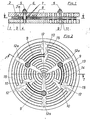
- valve plate 3 or 3 a or 3 b plays in a known manner. It is guided in a friction-free manner by its increasing arcuate handlebars 9 or 13a or 13b distributed in the circumferential direction, the roots 10 of which are cut in the middle in a web 12 of the valve plate 3 with fillets 15.
- the handlebars 9 and 13 a and 13 b run parallel over a ring 11 of the seat 1 and form at their free end a clamping ring 7 a, which, together with other lifting shims 7, surrounds a mounting screw 5 and 6, respectively each penetrates a different web 12 a, with the opening edges 14 in the valve plate 3 or 3 a or 3 b which spare the handlebars 9 with movement play 13 and lie above and between the edges of the respectively adjacent seat ring 11.
- the valve plate 3 is loaded in a known manner in the illustrated closed position by helical compression springs B which are nested in the catcher 2.
- the exemplary embodiments also show a damping plate 4 known per se, which is designed and arranged congruently to the valve plate 3 or 3 a or 3 b, and the handlebars of which are fixed between the lifting shims 7 on the mounting screws 5 in the same way as the handlebars 9 the valve plate 3.
- two steering rings 13 a, 13 b are arranged concentrically to one another in the radially inner and outer regions of the webs 12, 12 a, the lifting inserts 7 c of the inner clamps have a smaller overall thickness dimension than the stroke inserts 7 b of the radially outer clamps.
- a central pin 15 a is added to a handlebar rim 13a, the stroke inserts 7d of which are less thick than the stroke inserts 7b of the screw connections 6 of the handlebar rim.
- a convex elastic prestress is achieved between the seat and the catcher, which is exaggerated for clarity.
- the seat may bulge outwards from the flat position of the seat surface by a maximum of about 0.07 mm under the maximum permissible load against the pressure side at the end of the closing stroke if this Valve should still close tightly.
- the arrow height of the reversed elastic prestressing of the seat and the catcher is also approximately 0.07 mm in each of the last two exemplary embodiments.
- the seat may therefore deform towards the end of the closing stroke by a total of 0.14 mm, so that it requires a much smaller material thickness, which means a material saving of 56% for the seat in the illustrated exemplary embodiments and a reduction in the clearance for the pressure valve by approx 60% and better damping of the impact of the valve plate against the seat due to its reduced mass.
- the better damping of the closing stroke allows the valve to be operated in piston machines with higher ones Speed, which means a further increase in the delivery rate for a given outer diameter of the valve.
- the seat In the relaxed state, the seat is machined flat with the surface grinding machine to a flatness of 0.01 mm.
Landscapes
- Engineering & Computer Science (AREA)
- General Engineering & Computer Science (AREA)
- Mechanical Engineering (AREA)
- Lift Valve (AREA)
- Details Of Valves (AREA)
Claims (6)
Priority Applications (1)
| Application Number | Priority Date | Filing Date | Title |
|---|---|---|---|
| AT83110896T ATE24950T1 (de) | 1982-11-06 | 1983-11-02 | Plattenventil mit aussermittig ansetzenden ventilplattenlenkern. |
Applications Claiming Priority (4)
| Application Number | Priority Date | Filing Date | Title |
|---|---|---|---|
| DE3241050 | 1982-11-06 | ||
| DE3241050 | 1982-11-06 | ||
| DE3307118A DE3307118C2 (de) | 1982-11-06 | 1983-03-01 | Plattenventil mit außermittig ansetzenden Ventilplattenlenkern |
| DE3307118 | 1983-03-01 |
Publications (2)
| Publication Number | Publication Date |
|---|---|
| EP0108997A1 EP0108997A1 (fr) | 1984-05-23 |
| EP0108997B1 true EP0108997B1 (fr) | 1987-01-14 |
Family
ID=25805577
Family Applications (1)
| Application Number | Title | Priority Date | Filing Date |
|---|---|---|---|
| EP19830110896 Expired EP0108997B1 (fr) | 1982-11-06 | 1983-11-02 | Soupape à plateau avec bras d'articulation situés hors du centre |
Country Status (3)
| Country | Link |
|---|---|
| US (1) | US4516602A (fr) |
| EP (1) | EP0108997B1 (fr) |
| DE (2) | DE3307118C2 (fr) |
Families Citing this family (7)
| Publication number | Priority date | Publication date | Assignee | Title |
|---|---|---|---|---|
| DE3562813D1 (en) * | 1985-07-20 | 1988-06-23 | Dienes Werke | Plate valve with concentrically fastened guide arms |
| JPH07174071A (ja) * | 1993-08-10 | 1995-07-11 | Sanden Corp | 圧縮機の吐出機構 |
| AT412303B (de) * | 2000-04-18 | 2004-12-27 | Hoerbiger Ventilwerke Gmbh | Ventil |
| WO2010139917A1 (fr) * | 2009-06-03 | 2010-12-09 | The Technology Partnership Plc | Soupape |
| KR101275517B1 (ko) * | 2011-03-22 | 2013-07-05 | 주식회사 다윈프릭션 | 실린더 블록 및 이를 포함한 유압 기기 |
| EP3762638B1 (fr) * | 2018-03-08 | 2022-03-02 | Burckhardt Compression AG | Soupape à plaque ainsi que son procédé de fonctionnement |
| CN110170758B (zh) * | 2019-07-01 | 2020-11-06 | 湖南鑫众工业装备有限责任公司 | 一种多工位激光快速切割工作台 |
Family Cites Families (10)
| Publication number | Priority date | Publication date | Assignee | Title |
|---|---|---|---|---|
| DD33028A (fr) * | ||||
| US921892A (en) * | 1906-12-26 | 1909-05-18 | Fredrick William Rogler | Ring-valve. |
| FR443165A (fr) * | 1912-04-30 | 1912-09-18 | Piguet Const Mecaniques Ets | Soupape automatique |
| DE1425622C2 (de) * | 1963-08-09 | 1975-05-07 | Dienes Werke Fuer Maschinenteile Kg, 5063 Overath | Plattenventil für trockenlaufende Verdichter |
| DE1500015A1 (de) * | 1965-09-09 | 1969-05-14 | Kurt Ehmann | Ventil fuer Kolbenkompressoren |
| FR2025245A1 (fr) * | 1968-12-04 | 1970-09-04 | Dienes Werke Maschinen | |
| GB1406278A (en) * | 1972-12-15 | 1975-09-17 | Metallic Valve Co Ltd | Plate component for use in a plate type non-return valve |
| US4196746A (en) * | 1976-05-28 | 1980-04-08 | Broyan Valve Co., Inc. | Gas compressor valve |
| AT348088B (de) * | 1977-07-01 | 1979-01-25 | Enfo Grundlagen Forschungs Ag | Verschlusslamelle fuer ein ventil mit mehreren, konzentrisch angeordneten durchgangskanaelen |
| US4402342A (en) * | 1981-10-16 | 1983-09-06 | Paget Win W | Compressor valve |
-
1983
- 1983-03-01 DE DE3307118A patent/DE3307118C2/de not_active Expired
- 1983-11-01 US US06/547,567 patent/US4516602A/en not_active Expired - Fee Related
- 1983-11-02 DE DE8383110896T patent/DE3369176D1/de not_active Expired
- 1983-11-02 EP EP19830110896 patent/EP0108997B1/fr not_active Expired
Also Published As
| Publication number | Publication date |
|---|---|
| EP0108997A1 (fr) | 1984-05-23 |
| US4516602A (en) | 1985-05-14 |
| DE3369176D1 (en) | 1987-02-19 |
| DE3307118A1 (de) | 1984-05-10 |
| DE3307118C2 (de) | 1985-03-21 |
Similar Documents
| Publication | Publication Date | Title |
|---|---|---|
| DE2713599C2 (fr) | ||
| DE4140833C2 (fr) | ||
| EP0162238B1 (fr) | Machine à pistons axiaux, en particulier pompe du type à plateau incliné | |
| DE69603841T2 (de) | Hydrodynamisches axial folienlager mit in umfangrichtung verschobenen elastischen folien | |
| DE2452643A1 (de) | Ventil | |
| DE3319822A1 (de) | Hydraulikpumpe mit vorkompressionsventil | |
| DE102009030614A1 (de) | Freilauf-Käfigring mit Fliehkraftabhebung | |
| EP0108997B1 (fr) | Soupape à plateau avec bras d'articulation situés hors du centre | |
| EP0300994B1 (fr) | Soupape pour compresseur | |
| DE1903891C3 (de) | Federplatte für Mehrringventile | |
| EP1509308B1 (fr) | Dispositif de filtration de fluides achemines sous haute pression | |
| EP4476444A1 (fr) | Soupape pour un compresseur à piston et procédé de fonctionnement d'une telle soupape | |
| EP0604385B1 (fr) | Soupape automatique | |
| DE69715919T2 (de) | Plattenwärmetauscher | |
| AT411241B (de) | Einrichtung zum verriegeln der endlagen von beweglichen weichenteilen | |
| AT504956B1 (de) | Schliess- und dämpfungsscheiben | |
| DE2848737C2 (de) | Membran zum Getrennthalten zweier benachbarter Räume | |
| EP0770196A2 (fr) | Soupape antiretour | |
| EP0392383A1 (fr) | Vanne à tiroir | |
| EP0225477A2 (fr) | Piston pour moteurs à combustion interne | |
| DE8231116U1 (de) | Plattenventil mit aussermittig ansetzenden ventilplattenlenkern | |
| DE3541495C1 (de) | Federbelastetes Sicherheitsventil fuer Gase und Daempfe | |
| AT413139B (de) | Ringplattenventil für kolbenkompressoren | |
| EP0544137A2 (fr) | Assemblage pour la table ou le coulisseau d'une machine de formage | |
| EP0180098B1 (fr) | Chambre de combustion |
Legal Events
| Date | Code | Title | Description |
|---|---|---|---|
| PUAI | Public reference made under article 153(3) epc to a published international application that has entered the european phase |
Free format text: ORIGINAL CODE: 0009012 |
|
| 17P | Request for examination filed |
Effective date: 19840120 |
|
| AK | Designated contracting states |
Designated state(s): AT BE CH DE FR GB IT LI LU NL SE |
|
| ITF | It: translation for a ep patent filed | ||
| GRAA | (expected) grant |
Free format text: ORIGINAL CODE: 0009210 |
|
| AK | Designated contracting states |
Kind code of ref document: B1 Designated state(s): AT BE CH DE FR GB IT LI LU NL SE |
|
| REF | Corresponds to: |
Ref document number: 24950 Country of ref document: AT Date of ref document: 19870115 Kind code of ref document: T |
|
| REF | Corresponds to: |
Ref document number: 3369176 Country of ref document: DE Date of ref document: 19870219 |
|
| ET | Fr: translation filed | ||
| PLBI | Opposition filed |
Free format text: ORIGINAL CODE: 0009260 |
|
| PG25 | Lapsed in a contracting state [announced via postgrant information from national office to epo] |
Ref country code: SE Effective date: 19871103 |
|
| 26 | Opposition filed |
Opponent name: HOERBIGER VENTILWERKE AG Effective date: 19870916 |
|
| NLR1 | Nl: opposition has been filed with the epo |
Opponent name: HOERBIGER VENTILWERKE AG |
|
| PG25 | Lapsed in a contracting state [announced via postgrant information from national office to epo] |
Ref country code: LU Free format text: LAPSE BECAUSE OF NON-PAYMENT OF DUE FEES Effective date: 19871130 |
|
| PG25 | Lapsed in a contracting state [announced via postgrant information from national office to epo] |
Ref country code: NL Effective date: 19880601 |
|
| NLV4 | Nl: lapsed or anulled due to non-payment of the annual fee | ||
| REG | Reference to a national code |
Ref country code: CH Ref legal event code: PL |
|
| PG25 | Lapsed in a contracting state [announced via postgrant information from national office to epo] |
Ref country code: GB Effective date: 19881102 Ref country code: AT Effective date: 19881102 |
|
| PG25 | Lapsed in a contracting state [announced via postgrant information from national office to epo] |
Ref country code: BE Effective date: 19881130 |
|
| BERE | Be: lapsed |
Owner name: DIENES WERKE FUR MASCHINENTEILE G.M.B.H. & CO K.G Effective date: 19881130 |
|
| RDAG | Patent revoked |
Free format text: ORIGINAL CODE: 0009271 |
|
| STAA | Information on the status of an ep patent application or granted ep patent |
Free format text: STATUS: PATENT REVOKED |
|
| GBPR | Gb: patent revoked under art. 102 of the ep convention designating the uk as contracting state | ||
| 27W | Patent revoked |
Effective date: 19890302 |
|
| GBPC | Gb: european patent ceased through non-payment of renewal fee | ||
| EUG | Se: european patent has lapsed |
Ref document number: 83110896.4 Effective date: 19880609 |