EP0109024A1 - Ligne pour courant fort triphasé - Google Patents
Ligne pour courant fort triphasé Download PDFInfo
- Publication number
- EP0109024A1 EP0109024A1 EP83111096A EP83111096A EP0109024A1 EP 0109024 A1 EP0109024 A1 EP 0109024A1 EP 83111096 A EP83111096 A EP 83111096A EP 83111096 A EP83111096 A EP 83111096A EP 0109024 A1 EP0109024 A1 EP 0109024A1
- Authority
- EP
- European Patent Office
- Prior art keywords
- conductors
- current line
- winding
- line according
- transformer
- Prior art date
- Legal status (The legal status is an assumption and is not a legal conclusion. Google has not performed a legal analysis and makes no representation as to the accuracy of the status listed.)
- Granted
Links
- 239000004020 conductor Substances 0.000 claims abstract description 78
- 238000004804 winding Methods 0.000 claims abstract description 40
- 229910000831 Steel Inorganic materials 0.000 claims abstract description 4
- 238000002844 melting Methods 0.000 claims abstract description 4
- 230000008018 melting Effects 0.000 claims abstract description 4
- 239000010959 steel Substances 0.000 claims abstract description 4
- 230000005540 biological transmission Effects 0.000 claims abstract description 3
- 238000007789 sealing Methods 0.000 claims description 3
- IHQKEDIOMGYHEB-UHFFFAOYSA-M sodium dimethylarsinate Chemical class [Na+].C[As](C)([O-])=O IHQKEDIOMGYHEB-UHFFFAOYSA-M 0.000 claims description 3
- 239000002826 coolant Substances 0.000 claims description 2
- 238000011161 development Methods 0.000 description 3
- 230000018109 developmental process Effects 0.000 description 3
- XEEYBQQBJWHFJM-UHFFFAOYSA-N Iron Chemical group [Fe] XEEYBQQBJWHFJM-UHFFFAOYSA-N 0.000 description 2
- 238000001816 cooling Methods 0.000 description 2
- 230000001939 inductive effect Effects 0.000 description 2
- 239000003795 chemical substances by application Substances 0.000 description 1
- 239000000110 cooling liquid Substances 0.000 description 1
- 238000010438 heat treatment Methods 0.000 description 1
- 239000011810 insulating material Substances 0.000 description 1
- 239000002184 metal Substances 0.000 description 1
- 229910052751 metal Inorganic materials 0.000 description 1
- 125000006850 spacer group Chemical group 0.000 description 1
Images


Classifications
-
- H—ELECTRICITY
- H01—ELECTRIC ELEMENTS
- H01B—CABLES; CONDUCTORS; INSULATORS; SELECTION OF MATERIALS FOR THEIR CONDUCTIVE, INSULATING OR DIELECTRIC PROPERTIES
- H01B5/00—Non-insulated conductors or conductive bodies characterised by their form
-
- H—ELECTRICITY
- H01—ELECTRIC ELEMENTS
- H01B—CABLES; CONDUCTORS; INSULATORS; SELECTION OF MATERIALS FOR THEIR CONDUCTIVE, INSULATING OR DIELECTRIC PROPERTIES
- H01B9/00—Power cables
- H01B9/001—Power supply cables for the electrodes of electric-welding apparatus or electric-arc furnaces
-
- H—ELECTRICITY
- H01—ELECTRIC ELEMENTS
- H01F—MAGNETS; INDUCTANCES; TRANSFORMERS; SELECTION OF MATERIALS FOR THEIR MAGNETIC PROPERTIES
- H01F27/00—Details of transformers or inductances, in general
- H01F27/02—Casings
- H01F27/04—Leading of conductors or axles through casings, e.g. for tap-changing arrangements
-
- H—ELECTRICITY
- H01—ELECTRIC ELEMENTS
- H01F—MAGNETS; INDUCTANCES; TRANSFORMERS; SELECTION OF MATERIALS FOR THEIR MAGNETIC PROPERTIES
- H01F27/00—Details of transformers or inductances, in general
- H01F27/28—Coils; Windings; Conductive connections
- H01F27/2823—Wires
- H01F27/2828—Construction of conductive connections, of leads
Definitions
- the invention relates to a high-current line for three-phase current for the transmission of large electrical powers with very large currents with small voltage differences from a transformer to a neighboring bulk consumer, for example a steel melting furnace or an electrolytic bath, via conductors which are very wide in cross section in relation to their thickness.
- the lines for such applications are, as can be seen, for example, from the connections of an oven transformer on page 2 of the transformer letter 29 published by the Transformatoren Union AG from April 1978, usually designed so that the individual conductors roughly the longitudinal edges of a three-sided column form.
- a rotating stray field is formed outside of the conductors represented by plates or tubes.
- Metallic or electrically conductive sheaths enclosing the entire line are therefore to be avoided because each such sheath is to be regarded as an externally attached short-circuit rotor which constantly absorbs the starting current.
- the transformers provided for supplying steel melting furnaces and the like are equipped with oil cooling.
- the active part of these transformers is therefore installed in a boiler filled with oil, through the side wall of which the winding leads must be led.
- the conductors In the area of these bushings, too, the conductors have a very large width in relation to their thickness. Since the broadsides of the Due to the parallel winding axes themselves are also parallel to each other and at the same time the centroids of the conductor cross-sectional areas form the corners of an approximately equilateral triangle, the face ends of the conductors are practically opposite one another in the area of the leadthrough.
- the invention is based on the object of creating a high-current line for transmitting very powerful currents from a large transformer to an adjacent large electrical consumer and thereby loading all cross-sectional parts of the conductors used with approximately the same current by keeping the line inductance small.
- the object of the invention is achieved in that all individual conductors of a line from the winding in the transformer to the consumer in the area of the winding rejection as well as in the area of the passage through the boiler wall and as in an adjoining conductor section are each with their broad sides and face each other completely cover each other and that the width of these conductors is approximately equal to the winding height in the transformer.
- the line-feeding undervoltage windings are in three corner switched by connecting the winding rejection of an undervoltage winding on one end leg closer to the middle leg to the rejection of the winding on the middle leg facing it and by leading the rejection of the windings on the end legs facing the ends out through the boiler wall and are only galvanically connected to one another shortly before or directly via the load path of the consumer and thereby form the third triangle point in the delta connection.
- the ratio of the width of the conductors to their thickness is expediently between 50 and 150, preferably 100, and the distance between the conductors is greater than their thickness.
- a high-current line designed according to the invention is very advantageous because there is practically no magnetic voltage generated by it outside of the space enclosed by its conductors.
- the magnetic voltage in the three spaces between the conductors is symmetrical. Since the flow between flat conductors, which face each other with the large cross-sectional width, is guided very well due to the eddy currents which form easily, there is practically no scatter outside the conductors.
- the inductive voltage drop in the cable routing according to the invention is also extremely small because the width of the conductors is much larger than their thickness and at the same time the distance of the conductors from one another is greater than the thickness of the conductors, but in absolute terms is very small. This results in a further advantage of the high-current line according to the invention in that the line requires less driving voltage, so that a lower nominal power for the transformer than with conventional arrangements is sufficient for a given consumer power.
- the two external conductors are connected at the top and bottom with a crescent-shaped sealing strip to form a tube comprising the other two conductors and through which a coolant flows.
- each of the conductors is composed of a plurality of electrically and spatially parallel, coolant-flowed tubes, and the voltage between two spatially adjacent conductors can be set individually.
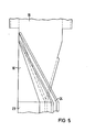
- the high-current line ends in a transfer piece in which the four conductors terminate in one in cross section three V-shaped conductors are led to a three-star star-composed conductor section, the outlets of the windings on the end legs facing the ends of the transformer being connected to the same V-shaped conductor.
- Each of these V-shaped - 'conductors expediently ends in a triangular plate which is connected to a connection pole of the consumer via a flexible conductor bundle or via a series connection of a tube and a flexible conductor bundle.
- An iron core carries with its middle leg 1 and end legs 2 and 3 radially inner high-voltage windings 4 and undervoltage windings 5, 6 and 7 arranged radially above it.
- the undervoltage windings 5, 6 and 7 each consist of one turn and are bent from a sheet metal plate, the width of which is equal to that Winding length between a lower yoke 8 and an upper yoke, not shown.
- the yokes 8 connect the ends of the end legs 2 and 3 to one another and to the ends of the middle leg 1.
- the iron core is placed together with the high-voltage windings 4 and the low-voltage windings 5, 6 and 7 in a boiler with 01 side walls 9 filled with 01.
- Winding rejections 10, 11, 12, 13, 14 and 15 are bent from extensions of the winding conductor of the respective undervoltage winding 5, 6 and 7 and are therefore as wide as the winding 5, 6 and 7 is long in the direction of its winding axis.
- the winding rejections 10 to 15 are led out of the boiler through a multiple bushing 16 through the boiler side wall 9.
- the winding leads 11 and 12 or 13 and 14 are each connected to one another and continued via a common thicker conductor 17 or 18.
- the conductors 17 and 18 and the extensions of the winding leads 10 and 15 run spatially parallel and cover one another over their full width. To fix this position, the conductors 17 and 18 and the winding leads 10 and 15 are pressed onto spacer blocks 20 made of insulating material by means not shown.
- the extensions of the winding leads 10 and 15 are supplemented outside of the boiler by crescent-shaped sealing strips 21 to form a tube 19 which carries the tension of the third corner point of the delta connection.
- the tube 19 also serves to guide a cooling liquid and, by building up a line cooling system, enables a further increase in the operational reliability of the high-current line. With an appropriate arrangement of the terminals on the consumer to be supplied, the pipe 19 together with the conductors 17 and 18 is brought up to this directly.
- the connecting devices of the consumer often form an approximately equilateral triangle with the focal points of their connecting terminals, so that it is necessary to transfer the line according to the invention into a triangulated line.
- a transfer piece according to FIGS. 3, 4 and 5 is used.
- the conductors 17 and 18 and the tube 19 are connected to conductors 22, 23 and 24 with a V-shaped cross section by the flat conductors 17 and 18 and the pipe 19, which has been broken up again into two flat bands, are each rotated half by 120 °.
- the three conductors 22, 23 and 24 which are V-shaped in cross section are combined to form a three-pointed star.
- a pulsating flow prevails between the opposite legs of the conductors 22, 23 and 24, while a rotating stray field is generated outside and around the conductor star.
- the conductors 22, 23 and 24 combined to form the star of the conductor, however, enable problem-free connection via flexible intermediate conductors to consumers provided for this purpose. It is useful to connect the free ends of the conductors 22, 23 and 24 to flexible intermediate conductors across the longitudinal axis of the high-current line on the cross-sectionally V-shaped conductors 22, 23 and 24 attached plates.
Landscapes
- Engineering & Computer Science (AREA)
- Power Engineering (AREA)
- General Induction Heating (AREA)
- Coils Of Transformers For General Uses (AREA)
- Transformers For Measuring Instruments (AREA)
- Emergency Protection Circuit Devices (AREA)
- Thermistors And Varistors (AREA)
- Waveguide Switches, Polarizers, And Phase Shifters (AREA)
- Housings And Mounting Of Transformers (AREA)
Priority Applications (1)
| Application Number | Priority Date | Filing Date | Title |
|---|---|---|---|
| AT83111096T ATE26038T1 (de) | 1982-11-16 | 1983-11-07 | Hochstromleitung fuer drehstrom. |
Applications Claiming Priority (2)
| Application Number | Priority Date | Filing Date | Title |
|---|---|---|---|
| DE19823242438 DE3242438A1 (de) | 1982-11-16 | 1982-11-16 | Hochstromleitung fuer drehstrom |
| DE3242438 | 1982-11-16 |
Publications (2)
| Publication Number | Publication Date |
|---|---|
| EP0109024A1 true EP0109024A1 (fr) | 1984-05-23 |
| EP0109024B1 EP0109024B1 (fr) | 1987-03-18 |
Family
ID=6178301
Family Applications (1)
| Application Number | Title | Priority Date | Filing Date |
|---|---|---|---|
| EP83111096A Expired EP0109024B1 (fr) | 1982-11-16 | 1983-11-07 | Ligne pour courant fort triphasé |
Country Status (4)
| Country | Link |
|---|---|
| EP (1) | EP0109024B1 (fr) |
| JP (1) | JPS59103317A (fr) |
| AT (1) | ATE26038T1 (fr) |
| DE (2) | DE3242438A1 (fr) |
Cited By (2)
| Publication number | Priority date | Publication date | Assignee | Title |
|---|---|---|---|---|
| EP0278098A3 (en) * | 1987-02-09 | 1988-10-12 | Elpatronic Ag | Resistance seam-welding machine |
| CN108922746A (zh) * | 2018-06-26 | 2018-11-30 | 河南森源电气股份有限公司 | 三相变压器 |
Families Citing this family (4)
| Publication number | Priority date | Publication date | Assignee | Title |
|---|---|---|---|---|
| DE3411141C2 (de) * | 1984-03-26 | 1986-07-31 | Transformatoren Union Ag, 7000 Stuttgart | Transformator mit Hochstromdurchführung |
| DE3629310A1 (de) * | 1986-08-28 | 1988-03-10 | Transformatoren Union Ag | Hochstromleiter fuer sondertransformatoren |
| DE9105967U1 (de) * | 1991-05-14 | 1992-09-17 | Siemens AG, 8000 München | Transformatorspule mit Anschlußschienen |
| DE19947917A1 (de) * | 1999-10-06 | 2001-04-12 | Abb Research Ltd | Transformator |
Citations (4)
| Publication number | Priority date | Publication date | Assignee | Title |
|---|---|---|---|---|
| AT148848B (de) * | 1935-02-05 | 1937-03-10 | Ludwig Gavanda Dr Ing | Ein- oder Mehrphasenhochstromleitung. |
| US3125622A (en) * | 1960-07-25 | 1964-03-17 | Conductors for arc furnaces | |
| DE2501510B2 (de) * | 1975-01-16 | 1978-06-22 | Transformatoren Union Ag, 7000 Stuttgart | Wicklung für Transformatoren und Drosseln |
| US4174509A (en) * | 1977-12-29 | 1979-11-13 | General Electric Company | Furnace transformer having a low-voltage internally-connected delta winding |
-
1982
- 1982-11-16 DE DE19823242438 patent/DE3242438A1/de not_active Withdrawn
-
1983
- 1983-11-07 EP EP83111096A patent/EP0109024B1/fr not_active Expired
- 1983-11-07 AT AT83111096T patent/ATE26038T1/de not_active IP Right Cessation
- 1983-11-07 DE DE8383111096T patent/DE3370400D1/de not_active Expired
- 1983-11-16 JP JP58215900A patent/JPS59103317A/ja active Pending
Patent Citations (4)
| Publication number | Priority date | Publication date | Assignee | Title |
|---|---|---|---|---|
| AT148848B (de) * | 1935-02-05 | 1937-03-10 | Ludwig Gavanda Dr Ing | Ein- oder Mehrphasenhochstromleitung. |
| US3125622A (en) * | 1960-07-25 | 1964-03-17 | Conductors for arc furnaces | |
| DE2501510B2 (de) * | 1975-01-16 | 1978-06-22 | Transformatoren Union Ag, 7000 Stuttgart | Wicklung für Transformatoren und Drosseln |
| US4174509A (en) * | 1977-12-29 | 1979-11-13 | General Electric Company | Furnace transformer having a low-voltage internally-connected delta winding |
Cited By (3)
| Publication number | Priority date | Publication date | Assignee | Title |
|---|---|---|---|---|
| EP0278098A3 (en) * | 1987-02-09 | 1988-10-12 | Elpatronic Ag | Resistance seam-welding machine |
| CN108922746A (zh) * | 2018-06-26 | 2018-11-30 | 河南森源电气股份有限公司 | 三相变压器 |
| CN108922746B (zh) * | 2018-06-26 | 2023-12-22 | 河南森源电气股份有限公司 | 三相变压器 |
Also Published As
| Publication number | Publication date |
|---|---|
| DE3370400D1 (en) | 1987-04-23 |
| JPS59103317A (ja) | 1984-06-14 |
| ATE26038T1 (de) | 1987-04-15 |
| DE3242438A1 (de) | 1984-05-17 |
| EP0109024B1 (fr) | 1987-03-18 |
Similar Documents
| Publication | Publication Date | Title |
|---|---|---|
| EP0102513B1 (fr) | Transformateur à sec avec enroulements fondus dans une résine de coulée | |
| CH663120A5 (de) | Staender eines generators. | |
| DE1803363A1 (de) | Elektrische Mittelspannungsleitung zur Leistungsuebertragung | |
| EP0109024B1 (fr) | Ligne pour courant fort triphasé | |
| DE2456092C3 (de) | Drosselspule | |
| DE2417125C3 (de) | Leistungstransformator | |
| DE2953100C1 (de) | Hochspannungs-Transformations- und Gleichrichtereinrichtung | |
| DE102004030845A1 (de) | Schweißstromwandler | |
| DE2154398C3 (de) | Spannungstransformator zur vertikalen Aufstellung mit einem gestreckten Magnetkern | |
| DE2549327A1 (de) | Transformator | |
| EP2182533B1 (fr) | Transformateur | |
| DE202014006814U1 (de) | Wicklungsanordnung | |
| DE2115574B2 (de) | Leistungstransformator fuer mittelfrequenz | |
| CH643679A5 (en) | High-current inductor coil | |
| DE69231948T2 (de) | Ein hochspannungsstromtransformator mit automatisierter isolationsherstellung und lagerung | |
| EP2330603A1 (fr) | Transformateur doté d'un enroulement de bande | |
| EP0102941B1 (fr) | Enroulement à conducteurs transposés | |
| EP0166951B1 (fr) | Transformateur avec une traversée à forte intensité | |
| EP0166952B1 (fr) | Transformateur à forte intensité avec ajustement indirect de tension par circuit intermédiaire | |
| DE2627314C2 (de) | Wicklung für Transformatoren | |
| DE2237054C3 (de) | Wicklung für Transformatoren und Drosselspulen | |
| DE2501510C3 (de) | Wicklung für Transformatoren und Drosseln | |
| DE2554514C3 (de) | Transformator für große elektrische Leistungen | |
| EP1903583A1 (fr) | Traversée à forte intensité pour transformateur | |
| DE3213883C2 (de) | Schaltleitungsbündel für Transformatoren |
Legal Events
| Date | Code | Title | Description |
|---|---|---|---|
| PUAI | Public reference made under article 153(3) epc to a published international application that has entered the european phase |
Free format text: ORIGINAL CODE: 0009012 |
|
| AK | Designated contracting states |
Designated state(s): AT BE DE FR GB IT NL SE |
|
| 17P | Request for examination filed |
Effective date: 19840626 |
|
| RAP1 | Party data changed (applicant data changed or rights of an application transferred) |
Owner name: TRANSFORMATOREN UNION AKTIENGESELLSCHAFT |
|
| GRAA | (expected) grant |
Free format text: ORIGINAL CODE: 0009210 |
|
| AK | Designated contracting states |
Kind code of ref document: B1 Designated state(s): AT BE DE FR GB IT NL SE |
|
| REF | Corresponds to: |
Ref document number: 26038 Country of ref document: AT Date of ref document: 19870415 Kind code of ref document: T |
|
| REF | Corresponds to: |
Ref document number: 3370400 Country of ref document: DE Date of ref document: 19870423 |
|
| ET | Fr: translation filed | ||
| ITF | It: translation for a ep patent filed | ||
| PGFP | Annual fee paid to national office [announced via postgrant information from national office to epo] |
Ref country code: NL Payment date: 19871130 Year of fee payment: 5 |
|
| PLBE | No opposition filed within time limit |
Free format text: ORIGINAL CODE: 0009261 |
|
| STAA | Information on the status of an ep patent application or granted ep patent |
Free format text: STATUS: NO OPPOSITION FILED WITHIN TIME LIMIT |
|
| 26N | No opposition filed | ||
| PG25 | Lapsed in a contracting state [announced via postgrant information from national office to epo] |
Ref country code: GB Effective date: 19891107 Ref country code: AT Effective date: 19891107 |
|
| PG25 | Lapsed in a contracting state [announced via postgrant information from national office to epo] |
Ref country code: SE Effective date: 19891108 |
|
| PG25 | Lapsed in a contracting state [announced via postgrant information from national office to epo] |
Ref country code: BE Effective date: 19891130 |
|
| BERE | Be: lapsed |
Owner name: TRANSFORMATOREN UNION A.G. Effective date: 19891130 |
|
| PG25 | Lapsed in a contracting state [announced via postgrant information from national office to epo] |
Ref country code: NL Effective date: 19900601 |
|
| GBPC | Gb: european patent ceased through non-payment of renewal fee | ||
| NLV4 | Nl: lapsed or anulled due to non-payment of the annual fee | ||
| PG25 | Lapsed in a contracting state [announced via postgrant information from national office to epo] |
Ref country code: FR Effective date: 19900731 |
|
| REG | Reference to a national code |
Ref country code: FR Ref legal event code: ST |
|
| PGFP | Annual fee paid to national office [announced via postgrant information from national office to epo] |
Ref country code: DE Payment date: 19920128 Year of fee payment: 9 |
|
| PG25 | Lapsed in a contracting state [announced via postgrant information from national office to epo] |
Ref country code: DE Effective date: 19930803 |
|
| EUG | Se: european patent has lapsed |
Ref document number: 83111096.0 Effective date: 19900705 |