EP0109045A2 - Dispositif d'égalisation à adaptation automatique à la longueur d'un câble - Google Patents
Dispositif d'égalisation à adaptation automatique à la longueur d'un câble Download PDFInfo
- Publication number
- EP0109045A2 EP0109045A2 EP83111190A EP83111190A EP0109045A2 EP 0109045 A2 EP0109045 A2 EP 0109045A2 EP 83111190 A EP83111190 A EP 83111190A EP 83111190 A EP83111190 A EP 83111190A EP 0109045 A2 EP0109045 A2 EP 0109045A2
- Authority
- EP
- European Patent Office
- Prior art keywords
- equalizer
- correction filter
- roll
- control loop
- amplitude control
- Prior art date
- Legal status (The legal status is an assumption and is not a legal conclusion. Google has not performed a legal analysis and makes no representation as to the accuracy of the status listed.)
- Granted
Links
Images


Classifications
-
- H—ELECTRICITY
- H04—ELECTRIC COMMUNICATION TECHNIQUE
- H04L—TRANSMISSION OF DIGITAL INFORMATION, e.g. TELEGRAPHIC COMMUNICATION
- H04L25/00—Baseband systems
- H04L25/02—Details ; arrangements for supplying electrical power along data transmission lines
- H04L25/03—Shaping networks in transmitter or receiver, e.g. adaptive shaping networks
- H04L25/03878—Line equalisers; line build-out devices
-
- H—ELECTRICITY
- H04—ELECTRIC COMMUNICATION TECHNIQUE
- H04L—TRANSMISSION OF DIGITAL INFORMATION, e.g. TELEGRAPHIC COMMUNICATION
- H04L25/00—Baseband systems
- H04L25/02—Details ; arrangements for supplying electrical power along data transmission lines
- H04L25/03—Shaping networks in transmitter or receiver, e.g. adaptive shaping networks
- H04L25/03006—Arrangements for removing intersymbol interference
- H04L25/03012—Arrangements for removing intersymbol interference operating in the time domain
- H04L25/03019—Arrangements for removing intersymbol interference operating in the time domain adaptive, i.e. capable of adjustment during data reception
-
- H—ELECTRICITY
- H04—ELECTRIC COMMUNICATION TECHNIQUE
- H04L—TRANSMISSION OF DIGITAL INFORMATION, e.g. TELEGRAPHIC COMMUNICATION
- H04L25/00—Baseband systems
- H04L25/02—Details ; arrangements for supplying electrical power along data transmission lines
- H04L25/12—Compensating for variations in line impedance
Definitions
- the invention relates to an automatically adjusting to the cable length equalizer arrangement with band loading. limit for the transmission of digital signals, consisting of an equalizing amplifier, a correction filter and an amplitude control loop with comparison of the actual and target values.
- Digital signal regenerators in transmission systems with coaxial cables as the transmission medium have an automatic attenuation equalizer at the input to compensate for the distortions caused by frequency-dependent cable attenuation.
- the amplitude of the equalized signal e.g. the amplitude of the signal at the decision maker. This pulse amplitude must be as independent of the input pattern as possible. This is only the case if a certain band limit is observed in the equalizer. For interference signal and noise signal suppression, however, one is dependent on a stronger band limitation, which leads to different pulse heights in the signal path depending on the input pattern.
- the band limitation required for interference reduction is usually carried out as a roll-off band limitation, as described, for example, in the book by P. Bocker: "Data Transmission", Vol. 1, pages 98 to 114, (Springer Verlag 1978) is described.
- Transmission systems for higher bit rates, such as 34 Mbit / s, are only possible with the field lengths and transmission powers given there with a roll-off factor that is less than 1, so that r ⁇ 1 applies. This fact leads to signal overshoots, the level of which depends on the pulse train. This will be explained in more detail later with reference to FIG. 1.
- Another known arrangement which avoids the disadvantage of the pulse train-dependent equalizer setting is explained in detail in FIG. 2. The difficulties that arise in particular can be seen below.
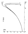
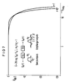
- the maximum gain of the equalizing amplifier for a roll-off factor of value 1 is greater and is at a higher frequency than that of an amplifier for a roll-off factor mm value ⁇ 1, this is shown and required in FIG. 7 especially with higher bit rates, such as 140 Mbit / s, more effort.
- the object of the invention is to provide an automatic equalizer arrangement in which the correction filter is not in the signal path but in the amplitude control loop, which means that less demands are made on the accuracy of the correction; furthermore, the equalizer amplifier only needs to be implemented for a band limitation with a roll-off factor ⁇ 1; Finally, it is also ensured that the correction filter dampens instabilities of the entire control loop due to its low-pass behavior for frequencies above the transmission band.
- this object is achieved in such a way that the equalizing amplifier is in the signal path, that the correction filter is in the amplitude control loop, in such a way that the output signal of this correction filter represents the actual variable for the amplitude control loop.
- FIGS. 1 to 3 and the equalizer circuits shown in FIG. 13 are briefly explained as follows. It should also be taken into account that elements with the same effect in the individual figures are provided with the same reference numbers, so that the explanations given for this are valid for all figures.
- a data signal 10 reaches an equalizer with band limitation, which has the reference number 1 there.
- the output signal E is fed to a decision maker 3, which is followed by a power amplifier 5.
- the output signal E is also fed to an amplitude control circuit 2, from which the band-limited equalizer 1 is in turn driven.
- Another signal E ' controls a clock recovery. nerator 4, which controls the decision maker 3.
- FIG. 2 A similar arrangement can also be seen in FIG. 2, in which the input signal is again denoted by 10 and the output signal by E.
- the amplitude control loop 2 ' can also be seen and the signal E', which is connected to the amplitude control loop 2 ' .
- a correction filter 6 is now provided in the signal path in the circuit diagram of FIG. 2, the effect of which will also be included later will go.
- the correction filter 6 lies in the amplitude control loop 2'-2.
- the output signal E is thus fed to this correction filter and then reaches the amplitude control loop 2.
- a roll-off factor r 0.7 in the signal path 10 / E is assumed and a roll-off factor r ⁇ 1 at the output of the correction filter 6 or at the input of the amplitude control loop 2.
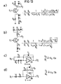
- FIG. 13 shows simple possibilities with which the transfer function required here can be implemented. A low-pass function and a resonance amplifier with a series and parallel damped circuit must appear.
- the transfer function U2 / U1 is specified directly on the individual circuits.
- U2 is the output voltage
- U1 the input voltage of an amplifier.
- a transistor T is used as the active element, at the base of which is the input voltage U1.
- the parallel connection of a resistor R p and a series arrangement of a capacitor C, a coil L and a loss resistor R s are located in the emitter circuit.
- the resistor and the capacitor C c are located in the collector circuit.
- FIG. 13b shows a possible circuit that is dual to the circuit shown in FIG. 13a.
- the series circuit comprising a resistor R E and a coil L E is provided in the emitter circuit, while the series circuit comprising a resistor R s is provided in the collector circuit. and the downstream parallel circuit consisting of a coil L, a resistor R p and a capacitor C.
- amplifiers are used which have the character of operational amplifiers and are therefore provided with the reference symbol Op.
- the amplification factor v goes against the value infinity.
- the parallel connection of a resistor and a capacitor lies in the negative feedback circuit, that is between the amplifier output and the amplifier input.
- the parallel connection of a resistor and a damped series resonant circuit is located in the amplifier input.
- the series circuit consists of an ohmic resistor in the negative feedback circuit, which is followed by the parallel circuit comprising a capacitor, a resistor and a coil, while the series circuit consists of a coil and a resistor in the amplifier input.
- FIG. 1 shows the block diagram of a conventional regenerator consisting of line attenuation equalizer 1 with amplitude control loop 2, decision maker 3 with clock recovery 4 and power amplifier 5.
- the band limitation in front of the decision maker required for noise reduction is usually carried out as an (approximate) roll-off band limitation according to the literature mentioned at the beginning.
- Transmission systems for higher bit rates e.g. 34 Mbit / s
- an r ⁇ 1 leads to signal overshoots, the level of which depends on the pulse sequence.
- the peak value rectifier in the amplitude control loop of the equalizer supplies a different value for random sequences than for a fixed pulse sequence and also different values for different sequences.
- the automatic equalizer will therefore only adjust to the correct value (if the time constant in the control loop is long enough) for random sequences or a certain fixed sequence.
- Fig. 2 shows a known arrangement that avoids the disadvantage of the pulse train dependent equalizer setting.
- the equalizer 1 includes a band limitation with r ⁇ 1, its output signal (E) is practically free from overshoots.
- the clock recovery 4 can also be derived from this signal E 'to reduce the basic jitter of the regenerator.
- the equalizer 1 is followed by an additional filter 6 (the theoretical amount of the transfer function is shown in FIG. 6) with a linear phase to reduce the roll-off factor.
- the correction filter 6 for roll-off conversion does not lie in the signal path here, but in the amplitude control loop 2, 2 ', which is why lower demands are made on the accuracy of the correction.
- the equalizer amplifier 1 can only be implemented for a band limitation with 1 ⁇ r.
- the theoretical transfer function of the line loss equalizer 1 is with the desired reception spectrum of a roll-off band-limited pulse, (A e is the reception amplitude, r the roll-off factor) the spectrum of a transmission pulse that approximates reality,
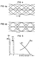
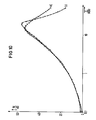
- Fig. 5 shows 20 log F K for different r.
- the line loss equalizers of this system can be implemented as follows.
- the roll-off factor is r ⁇ 0.7.
- 4a shows the associated eye diagram for a pseudo-random pulse train with its pattern-dependent overshoots.
- This output signal is not very suitable as a control criterion for controlling a variable damping equalizer.
- An equalizer for roll-off conversion from r ⁇ 0.7 to r ⁇ 1 is implemented as follows.
- FIG. 4b shows the eye diagram measured after the converter. This signal is suitable as a control criterion.
- the transfer function mentioned above is composed of a low-pass filter and a resonance amplifier with a series and parallel damped circuit.
- FIG. 13 already described at the beginning, shows simple implementation options for this.
Landscapes
- Engineering & Computer Science (AREA)
- Power Engineering (AREA)
- Computer Networks & Wireless Communication (AREA)
- Signal Processing (AREA)
- Cable Transmission Systems, Equalization Of Radio And Reduction Of Echo (AREA)
- Filters And Equalizers (AREA)
- Networks Using Active Elements (AREA)
- Communication Cables (AREA)
Priority Applications (1)
| Application Number | Priority Date | Filing Date | Title |
|---|---|---|---|
| AT83111190T ATE47638T1 (de) | 1982-11-11 | 1983-11-09 | Automatisch sich auf die kabellaenge einstellende entzerreranordnung. |
Applications Claiming Priority (2)
| Application Number | Priority Date | Filing Date | Title |
|---|---|---|---|
| DE19823241813 DE3241813A1 (de) | 1982-11-11 | 1982-11-11 | Automatisch sich auf die kabellaenge einstellende entzerreranordnung |
| DE3241813 | 1982-11-11 |
Publications (3)
| Publication Number | Publication Date |
|---|---|
| EP0109045A2 true EP0109045A2 (fr) | 1984-05-23 |
| EP0109045A3 EP0109045A3 (en) | 1987-04-29 |
| EP0109045B1 EP0109045B1 (fr) | 1989-10-25 |
Family
ID=6177928
Family Applications (1)
| Application Number | Title | Priority Date | Filing Date |
|---|---|---|---|
| EP83111190A Expired EP0109045B1 (fr) | 1982-11-11 | 1983-11-09 | Dispositif d'égalisation à adaptation automatique à la longueur d'un câble |
Country Status (5)
| Country | Link |
|---|---|
| US (1) | US4583235A (fr) |
| EP (1) | EP0109045B1 (fr) |
| JP (1) | JPS5997235A (fr) |
| AT (1) | ATE47638T1 (fr) |
| DE (2) | DE3241813A1 (fr) |
Families Citing this family (29)
| Publication number | Priority date | Publication date | Assignee | Title |
|---|---|---|---|---|
| JPS6083433A (ja) * | 1983-10-13 | 1985-05-11 | Fujitsu Ltd | 出力波形の等化方式 |
| US4759035A (en) * | 1987-10-01 | 1988-07-19 | Adtran | Digitally controlled, all rate equalizer |
| US4970722A (en) * | 1987-11-02 | 1990-11-13 | Amp Incorporated | Broadband local area network |
| US4835494A (en) * | 1988-04-20 | 1989-05-30 | Amp Incorporated | Automatic level control system for broadband cable systems |
| US5293405A (en) * | 1991-10-31 | 1994-03-08 | International Business Machines Corp. | Adaptive equalization and regeneration system |
| US5418789A (en) * | 1992-10-14 | 1995-05-23 | International Business Machines Corporation | Fast communication link bit error rate estimator |
| DE69225709D1 (de) * | 1992-10-15 | 1998-07-02 | Ibm | Einrichtung und Verfahren zur adaptiven Entzerrung in Tokenringübertragungseinrichtungen unter Verwendung von ungeschirmten verdrillten Kabelpaaren |
| US6047024A (en) * | 1997-08-22 | 2000-04-04 | Alcatel Internetworking, Inc. | Device for equalizing channel-distorted signals |
| US6188721B1 (en) | 1998-04-17 | 2001-02-13 | Lucent Technologies, Inc. | System and method for adaptive equalization of a waveform independent of absolute waveform peak value |
| US6466626B1 (en) | 1999-02-23 | 2002-10-15 | International Business Machines Corporation | Driver with in-situ variable compensation for cable attenuation |
| US6961373B2 (en) * | 2002-07-01 | 2005-11-01 | Solarflare Communications, Inc. | Method and apparatus for channel equalization |
| US7809021B2 (en) | 2002-07-10 | 2010-10-05 | Solarflare Communications, Inc. | Communication system and encoding method having low overhead |
| US7133425B2 (en) | 2002-07-10 | 2006-11-07 | Solarflare Communications, Inc. | Communication system |
| US7065167B2 (en) | 2002-07-10 | 2006-06-20 | Solarflare Communications, Inc. | Method and apparatus for constellation shaping |
| US7164764B2 (en) * | 2002-11-07 | 2007-01-16 | Solarflare Communications, Inc. | Method and apparatus for precode crosstalk mitigation |
| US6912208B2 (en) * | 2002-11-07 | 2005-06-28 | Solarflare Communications, Inc. | Method and apparatus for equalization and crosstalk mitigation |
| US8363535B2 (en) * | 2003-04-28 | 2013-01-29 | Marvell International Ltd. | Frequency domain echo and next cancellation |
| US20040213354A1 (en) * | 2003-04-28 | 2004-10-28 | Jones William W. | Mixed domain cancellation |
| US7002897B2 (en) * | 2003-04-28 | 2006-02-21 | Solarflare Communications, Inc. | Multiple channel interference cancellation |
| US8761387B2 (en) | 2006-05-04 | 2014-06-24 | Mindspeed Technologies, Inc. | Analog transmit crosstalk canceller |
| US7720068B2 (en) | 2006-08-23 | 2010-05-18 | Solarflare Communications, Inc. | Method and system for a multi-rate gigabit media independent interface |
| US7808407B2 (en) | 2007-06-15 | 2010-10-05 | Solarflare Communications, Inc. | Sub-channel distortion mitigation in parallel digital systems |
| US7844213B2 (en) * | 2007-07-31 | 2010-11-30 | The Directv Group, Inc. | Reducing spectral roll-off factors to increase spectral efficiency |
| US7948862B2 (en) | 2007-09-26 | 2011-05-24 | Solarflare Communications, Inc. | Crosstalk cancellation using sliding filters |
| US8984304B2 (en) * | 2007-11-12 | 2015-03-17 | Marvell International Ltd. | Active idle communication system |
| US8270389B2 (en) * | 2008-08-11 | 2012-09-18 | Marvell International Ltd. | Method of synchronization for low power idle |
| US8461848B2 (en) | 2008-12-10 | 2013-06-11 | Marvell International Ltd. | Cable diagnostics for Base-T systems |
| JP5664295B2 (ja) * | 2011-02-03 | 2015-02-04 | 富士通株式会社 | 通信装置および通信装置設定方法 |
| US11153135B1 (en) * | 2021-01-11 | 2021-10-19 | Texas Instruments Incorporated | Methods and systems for adaptive equalization with wide range of signal amplitudes |
Family Cites Families (8)
| Publication number | Priority date | Publication date | Assignee | Title |
|---|---|---|---|---|
| US3578914A (en) * | 1969-04-09 | 1971-05-18 | Lynch Communication Systems | Equalizer with automatic line build-out |
| US3763359A (en) * | 1972-05-15 | 1973-10-02 | Bell Telephone Labor Inc | Apparatus for equalizing a transmission system |
| US4003006A (en) * | 1975-10-06 | 1977-01-11 | Bell Telephone Laboratories, Incorporated | Pilot tone controlled adaptive amplitude equalizer |
| FR2419618A1 (fr) * | 1978-03-10 | 1979-10-05 | Cit Alcatel | Egaliseur automatique pour transmission numerique synchrone |
| GB2036509B (en) * | 1978-10-27 | 1983-01-26 | Kokusai Denshin Denwa Co Ltd | Automatic phase and amplitude equalisation of fm signals |
| US4251782A (en) * | 1979-01-17 | 1981-02-17 | Rockwell International Corporation | Multiple tuned circuit correction apparatus |
| GB2068196B (en) * | 1980-01-17 | 1984-02-15 | Standard Telephones Cables Ltd | Repeaters for digital transmission systems |
| US4430744A (en) * | 1981-12-18 | 1984-02-07 | Gte Automatic Electric Incorporated | Adaptive IF equalizer for digital transmission |
-
1982
- 1982-11-11 DE DE19823241813 patent/DE3241813A1/de not_active Withdrawn
-
1983
- 1983-10-27 US US06/546,124 patent/US4583235A/en not_active Expired - Fee Related
- 1983-10-31 JP JP58202915A patent/JPS5997235A/ja active Granted
- 1983-11-09 EP EP83111190A patent/EP0109045B1/fr not_active Expired
- 1983-11-09 AT AT83111190T patent/ATE47638T1/de not_active IP Right Cessation
- 1983-11-09 DE DE8383111190T patent/DE3380783D1/de not_active Expired
Also Published As
| Publication number | Publication date |
|---|---|
| EP0109045A3 (en) | 1987-04-29 |
| DE3241813A1 (de) | 1984-05-17 |
| US4583235A (en) | 1986-04-15 |
| ATE47638T1 (de) | 1989-11-15 |
| DE3380783D1 (en) | 1989-11-30 |
| EP0109045B1 (fr) | 1989-10-25 |
| JPS5997235A (ja) | 1984-06-05 |
| JPH0139254B2 (fr) | 1989-08-18 |
Similar Documents
| Publication | Publication Date | Title |
|---|---|---|
| EP0109045B1 (fr) | Dispositif d'égalisation à adaptation automatique à la longueur d'un câble | |
| EP0521342B1 (fr) | Egaliseur pour systèmes optiques de transmission d'informations | |
| DE19907530A1 (de) | D-Verstärker und Verfahren zum Erzeugen eines Bezugssignals, das repräsentativ für das Ausgangssignal eines D-Verstärkers ist | |
| EP0521341B1 (fr) | Egaliseur pour signaux de communications transmis par voie optique | |
| DE4113244A1 (de) | Programmierbare hf-filterschaltung | |
| DE3602509C2 (fr) | ||
| DE3888436T2 (de) | Leitungsanpassungsschaltungen. | |
| EP0004054B1 (fr) | Circuit d'égalisation automatique d'un signal | |
| DE10101950C1 (de) | Entscheidungsrückgekoppelte Entzerrervorrichtung | |
| EP0700153A2 (fr) | Circuit avec caractéristiques de transfert contrÔlables | |
| EP0030700A2 (fr) | Dispositif pour la correction d'un signal non modulé à large bande, en particulier d'un signal vidéo de couleur, dans un système d'enregistrement et de reproduction de signaux | |
| DE2753365C2 (de) | Schaltungsanordnung zur Wiedergabe von auf einem Medium aufgezeichneten breitbandigen Signalen | |
| DE2938378A1 (de) | Signalverarbeitungskreis | |
| DE2736951C2 (fr) | ||
| DE3206047C2 (de) | Anordnung zum Aufbereiten von Videosignalen | |
| DE1791202B2 (de) | Einstellbare elektrische entzerrerschaltung | |
| DE2755144C3 (de) | Schaltungsanordnung zur wahlweisen Dynamik-Kompression oder -Expansion | |
| DE69808654T2 (de) | Verfahren zum korrigieren von symbolverzerrung von mehrpegelpulsen in pulsfrequenzmodulationssystemen | |
| DE1002048B (de) | Verstaerker mit fehlangepassten Zwischenstufen-Netzwerken | |
| DE2430465B1 (de) | Adaptiver entzerrer zur entzerrung eines fernsehsignals | |
| EP0012977B1 (fr) | Circuit pour la détection et la localisation d'erreurs dans un système de transmission de signaux modulés par impulsions codées | |
| DE3201655A1 (de) | Schaltung fuer entzerrer | |
| DE1929996C3 (de) | Filter für elektrische Schwingungen | |
| EP0205182B1 (fr) | Egaliseur de temps de propagation réglable à pertes présentant au moins un point fixe du temps de propagation | |
| AT94693B (de) | Anordnung zum gleichzeitigen Telephonieren und Telegraphieren auf einem geschlossenen metallischen Stromkreis mit Belastungsspulen oder Verstärkern. |
Legal Events
| Date | Code | Title | Description |
|---|---|---|---|
| PUAI | Public reference made under article 153(3) epc to a published international application that has entered the european phase |
Free format text: ORIGINAL CODE: 0009012 |
|
| AK | Designated contracting states |
Designated state(s): AT BE CH DE FR GB IT LI NL SE |
|
| 17P | Request for examination filed |
Effective date: 19841219 |
|
| PUAL | Search report despatched |
Free format text: ORIGINAL CODE: 0009013 |
|
| AK | Designated contracting states |
Kind code of ref document: A3 Designated state(s): AT BE CH DE FR GB IT LI NL SE |
|
| 17Q | First examination report despatched |
Effective date: 19880725 |
|
| GRAA | (expected) grant |
Free format text: ORIGINAL CODE: 0009210 |
|
| AK | Designated contracting states |
Kind code of ref document: B1 Designated state(s): AT BE CH DE FR GB IT LI NL SE |
|
| PG25 | Lapsed in a contracting state [announced via postgrant information from national office to epo] |
Ref country code: SE Effective date: 19891025 Ref country code: NL Effective date: 19891025 Ref country code: GB Effective date: 19891025 |
|
| REF | Corresponds to: |
Ref document number: 47638 Country of ref document: AT Date of ref document: 19891115 Kind code of ref document: T |
|
| REF | Corresponds to: |
Ref document number: 3380783 Country of ref document: DE Date of ref document: 19891130 |
|
| ET | Fr: translation filed | ||
| ITF | It: translation for a ep patent filed | ||
| NLV1 | Nl: lapsed or annulled due to failure to fulfill the requirements of art. 29p and 29m of the patents act | ||
| GBV | Gb: ep patent (uk) treated as always having been void in accordance with gb section 77(7)/1977 [no translation filed] | ||
| PLBE | No opposition filed within time limit |
Free format text: ORIGINAL CODE: 0009261 |
|
| STAA | Information on the status of an ep patent application or granted ep patent |
Free format text: STATUS: NO OPPOSITION FILED WITHIN TIME LIMIT |
|
| 26N | No opposition filed | ||
| ITTA | It: last paid annual fee | ||
| PGFP | Annual fee paid to national office [announced via postgrant information from national office to epo] |
Ref country code: DE Payment date: 19960119 Year of fee payment: 13 |
|
| PGFP | Annual fee paid to national office [announced via postgrant information from national office to epo] |
Ref country code: CH Payment date: 19960216 Year of fee payment: 13 |
|
| PGFP | Annual fee paid to national office [announced via postgrant information from national office to epo] |
Ref country code: AT Payment date: 19961025 Year of fee payment: 14 |
|
| PGFP | Annual fee paid to national office [announced via postgrant information from national office to epo] |
Ref country code: BE Payment date: 19961114 Year of fee payment: 14 |
|
| PGFP | Annual fee paid to national office [announced via postgrant information from national office to epo] |
Ref country code: FR Payment date: 19961129 Year of fee payment: 14 |
|
| PG25 | Lapsed in a contracting state [announced via postgrant information from national office to epo] |
Ref country code: LI Effective date: 19961130 Ref country code: CH Effective date: 19961130 |
|
| REG | Reference to a national code |
Ref country code: CH Ref legal event code: PL |
|
| PG25 | Lapsed in a contracting state [announced via postgrant information from national office to epo] |
Ref country code: DE Effective date: 19970801 |
|
| PG25 | Lapsed in a contracting state [announced via postgrant information from national office to epo] |
Ref country code: AT Free format text: LAPSE BECAUSE OF NON-PAYMENT OF DUE FEES Effective date: 19971109 |
|
| PG25 | Lapsed in a contracting state [announced via postgrant information from national office to epo] |
Ref country code: FR Free format text: THE PATENT HAS BEEN ANNULLED BY A DECISION OF A NATIONAL AUTHORITY Effective date: 19971130 Ref country code: BE Free format text: LAPSE BECAUSE OF NON-PAYMENT OF DUE FEES Effective date: 19971130 |
|
| BERE | Be: lapsed |
Owner name: SIEMENS A.G. Effective date: 19971130 |
|
| REG | Reference to a national code |
Ref country code: FR Ref legal event code: ST |