EP0109192A1 - Procédé de fabrication d'une ébauche de fibre optique - Google Patents
Procédé de fabrication d'une ébauche de fibre optique Download PDFInfo
- Publication number
- EP0109192A1 EP0109192A1 EP83306243A EP83306243A EP0109192A1 EP 0109192 A1 EP0109192 A1 EP 0109192A1 EP 83306243 A EP83306243 A EP 83306243A EP 83306243 A EP83306243 A EP 83306243A EP 0109192 A1 EP0109192 A1 EP 0109192A1
- Authority
- EP
- European Patent Office
- Prior art keywords
- glass
- tube
- optical fiber
- clad
- core
- Prior art date
- Legal status (The legal status is an assumption and is not a legal conclusion. Google has not performed a legal analysis and makes no representation as to the accuracy of the status listed.)
- Granted
Links
- 239000013307 optical fiber Substances 0.000 title claims abstract description 49
- 238000000034 method Methods 0.000 title claims abstract description 30
- 239000011521 glass Substances 0.000 claims abstract description 87
- 239000007787 solid Substances 0.000 claims abstract description 6
- 239000000835 fiber Substances 0.000 claims abstract description 3
- 238000010438 heat treatment Methods 0.000 claims description 18
- VYPSYNLAJGMNEJ-UHFFFAOYSA-N silicon dioxide Inorganic materials O=[Si]=O VYPSYNLAJGMNEJ-UHFFFAOYSA-N 0.000 abstract description 37
- 239000010453 quartz Substances 0.000 abstract description 22
- 239000010409 thin film Substances 0.000 description 13
- 230000003287 optical effect Effects 0.000 description 8
- 239000000463 material Substances 0.000 description 7
- 229910001868 water Inorganic materials 0.000 description 7
- 230000010287 polarization Effects 0.000 description 6
- 229910052681 coesite Inorganic materials 0.000 description 5
- 229910052906 cristobalite Inorganic materials 0.000 description 5
- 229910052682 stishovite Inorganic materials 0.000 description 5
- 229910052905 tridymite Inorganic materials 0.000 description 5
- 239000002019 doping agent Substances 0.000 description 4
- 239000000377 silicon dioxide Substances 0.000 description 4
- 230000005540 biological transmission Effects 0.000 description 3
- 239000010408 film Substances 0.000 description 3
- 239000000203 mixture Substances 0.000 description 3
- 230000002093 peripheral effect Effects 0.000 description 3
- 230000008033 biological extinction Effects 0.000 description 2
- 238000000151 deposition Methods 0.000 description 2
- 230000000694 effects Effects 0.000 description 2
- 238000009877 rendering Methods 0.000 description 2
- 239000012808 vapor phase Substances 0.000 description 2
- XLYOFNOQVPJJNP-UHFFFAOYSA-N water Substances O XLYOFNOQVPJJNP-UHFFFAOYSA-N 0.000 description 2
- FGRBYDKOBBBPOI-UHFFFAOYSA-N 10,10-dioxo-2-[4-(N-phenylanilino)phenyl]thioxanthen-9-one Chemical compound O=C1c2ccccc2S(=O)(=O)c2ccc(cc12)-c1ccc(cc1)N(c1ccccc1)c1ccccc1 FGRBYDKOBBBPOI-UHFFFAOYSA-N 0.000 description 1
- 230000015572 biosynthetic process Effects 0.000 description 1
- 238000005229 chemical vapour deposition Methods 0.000 description 1
- 230000003247 decreasing effect Effects 0.000 description 1
- 230000008021 deposition Effects 0.000 description 1
- 238000009792 diffusion process Methods 0.000 description 1
- 238000002474 experimental method Methods 0.000 description 1
- 230000002349 favourable effect Effects 0.000 description 1
- 238000003780 insertion Methods 0.000 description 1
- 230000037431 insertion Effects 0.000 description 1
- 239000007788 liquid Substances 0.000 description 1
- 238000004519 manufacturing process Methods 0.000 description 1
- 238000005259 measurement Methods 0.000 description 1
- 230000001105 regulatory effect Effects 0.000 description 1
- 239000007858 starting material Substances 0.000 description 1
Images
Classifications
-
- C—CHEMISTRY; METALLURGY
- C03—GLASS; MINERAL OR SLAG WOOL
- C03B—MANUFACTURE, SHAPING, OR SUPPLEMENTARY PROCESSES
- C03B37/00—Manufacture or treatment of flakes, fibres, or filaments from softened glass, minerals, or slags
- C03B37/01—Manufacture of glass fibres or filaments
- C03B37/012—Manufacture of preforms for drawing fibres or filaments
- C03B37/01205—Manufacture of preforms for drawing fibres or filaments starting from tubes, rods, fibres or filaments
- C03B37/01225—Means for changing or stabilising the shape, e.g. diameter, of tubes or rods in general, e.g. collapsing
- C03B37/01248—Means for changing or stabilising the shape, e.g. diameter, of tubes or rods in general, e.g. collapsing by collapsing without drawing
-
- C—CHEMISTRY; METALLURGY
- C03—GLASS; MINERAL OR SLAG WOOL
- C03B—MANUFACTURE, SHAPING, OR SUPPLEMENTARY PROCESSES
- C03B37/00—Manufacture or treatment of flakes, fibres, or filaments from softened glass, minerals, or slags
- C03B37/01—Manufacture of glass fibres or filaments
- C03B37/012—Manufacture of preforms for drawing fibres or filaments
- C03B37/01205—Manufacture of preforms for drawing fibres or filaments starting from tubes, rods, fibres or filaments
- C03B37/01211—Manufacture of preforms for drawing fibres or filaments starting from tubes, rods, fibres or filaments by inserting one or more rods or tubes into a tube
- C03B37/01217—Manufacture of preforms for drawing fibres or filaments starting from tubes, rods, fibres or filaments by inserting one or more rods or tubes into a tube for making preforms of polarisation-maintaining optical fibres
-
- C—CHEMISTRY; METALLURGY
- C03—GLASS; MINERAL OR SLAG WOOL
- C03B—MANUFACTURE, SHAPING, OR SUPPLEMENTARY PROCESSES
- C03B37/00—Manufacture or treatment of flakes, fibres, or filaments from softened glass, minerals, or slags
- C03B37/01—Manufacture of glass fibres or filaments
- C03B37/012—Manufacture of preforms for drawing fibres or filaments
- C03B37/01205—Manufacture of preforms for drawing fibres or filaments starting from tubes, rods, fibres or filaments
- C03B37/01225—Means for changing or stabilising the shape, e.g. diameter, of tubes or rods in general, e.g. collapsing
-
- C—CHEMISTRY; METALLURGY
- C03—GLASS; MINERAL OR SLAG WOOL
- C03B—MANUFACTURE, SHAPING, OR SUPPLEMENTARY PROCESSES
- C03B37/00—Manufacture or treatment of flakes, fibres, or filaments from softened glass, minerals, or slags
- C03B37/01—Manufacture of glass fibres or filaments
- C03B37/012—Manufacture of preforms for drawing fibres or filaments
- C03B37/014—Manufacture of preforms for drawing fibres or filaments made entirely or partially by chemical means, e.g. vapour phase deposition of bulk porous glass either by outside vapour deposition [OVD], or by outside vapour phase oxidation [OVPO] or by vapour axial deposition [VAD]
- C03B37/018—Manufacture of preforms for drawing fibres or filaments made entirely or partially by chemical means, e.g. vapour phase deposition of bulk porous glass either by outside vapour deposition [OVD], or by outside vapour phase oxidation [OVPO] or by vapour axial deposition [VAD] by glass deposition on a glass substrate, e.g. by inside-, modified-, plasma-, or plasma modified- chemical vapour deposition [ICVD, MCVD, PCVD, PMCVD], i.e. by thin layer coating on the inside or outside of a glass tube or on a glass rod
-
- C—CHEMISTRY; METALLURGY
- C03—GLASS; MINERAL OR SLAG WOOL
- C03B—MANUFACTURE, SHAPING, OR SUPPLEMENTARY PROCESSES
- C03B2203/00—Fibre product details, e.g. structure, shape
- C03B2203/10—Internal structure or shape details
- C03B2203/22—Radial profile of refractive index, composition or softening point
- C03B2203/24—Single mode [SM or monomode]
-
- C—CHEMISTRY; METALLURGY
- C03—GLASS; MINERAL OR SLAG WOOL
- C03B—MANUFACTURE, SHAPING, OR SUPPLEMENTARY PROCESSES
- C03B2203/00—Fibre product details, e.g. structure, shape
- C03B2203/30—Polarisation maintaining [PM], i.e. birefringent products, e.g. with elliptical core, by use of stress rods, "PANDA" type fibres
Definitions
- the present invention relates to a method of producing an optical fiber preform. More particularly, it relates to a method of producing an optical fiber preform for obtaining an optical fiber in which at least one of a clad and a jacket effecting important functions in the optical transmission of the optical fiber has an elliptic cross section.
- optical fiber to be coupled with such optical integrated circuit must have the function of transmitting only a component in the direction of polarization in which the optical integrated circuit operates.
- Such optical fiber is called “single-polarization optical fiber", and it is important for a transmission line for optical communications and also for measurement use.
- the present inventors have realized an optical fiber having a predetermined elliptic layer by a method in which a glass thin film to become a core or a clad is formed on the inner wall of a glass tube by the chemical vapor deposition process (CVD process), and the glass tube is collapsed under heating so as to prepare a solid preform rod, the pressure of the interior of the tube being reduced.
- CVD process chemical vapor deposition process
- An object of the present invention is to provide a method by which an optical fiber preform for rendering at least one of a clad and a jacket elliptic in cross section is readily produced without restrictions to materials.
- the method of producing an optical fiber preform comprises i) the step of forming a glass thin film to become a clad layer, a glass thin film to become a jacket layer, or glass thin films to become a jacket layer and a clad layer, on an inner wall of a glass mother tube such as quartz tube, ii) the step of inserting a glass rod of circular cross section to become a core or a glass rod of circular cross section to become a core and a clad, into the glass mother tube subjected to the step i), and iii) the step of heating the glass mother tube with the rod inserted therein, to a predetermined temperature under a state under which the pressure inside said glass mother tube is reduced to be lower by a predetermined value than ambient pressure outside said glass mother tube.
- An optical fiber obtained by drawing the optical fiber preform produced by the method of the present invention has a three-layer structure which consists of the core (a central region through which light passes), the clad (a layer which serves to confine the light into the core, and which adjoins the outer side of the core and exhibits a refractive index lower than that of the core), and a support (the outermost layer which affords a mechanical strength to the optical fiber); or a four-layer structure in which the jacket (a layer which induces strain birefringence) is added between the clad and the support of the aforementioned three-layer structure.
- the parts of the optical fiber preform corresponding to the core, clad, jacket and support of the optical fiber shall be similarly called the core, clad, jacket and support, respectively.
- n 1 denote the refractive index of the core
- n 2 that of the clad
- n 3 that of the jacket
- each layer in step i) can be carried out by the well-known CVD process.
- the refractive indices may be adjusted by adding well-known dopants to the principal component of the respective materials, for example, Si0 2 .
- the glass rod of circular cross section for use in the step ii) may be made of a glass material which has a predetermined refractive index and which has the quality that is applied to the cores of ordinary optical fibers.
- the material can be readily produced by a well-known method which includes the step of depositing glass of a desired composition from a vapor phase serving as a starting material.
- the pressure inside the glass mother tube in the step iii) is preferably made 1 mm H 2 0 - 30 mm H 2 0 lower than the pressure outside the tube.
- the heating temperature and the moving speed of a heating source in the step iii) may be any conditions capable of collapsing the glass mother tube.
- the heating temperature is prefer- ablYset at 1700 °C - 2000 °C, and the moving speed of the heating source at 0.02mm/s - 0.4mm/s.
- the heating temperature falls outside the above range, it may be difficult to render the glass film elliptic.
- the moving speed of the heating source is higher than the above speed (the heating time becomes shorter), it may be similarly difficult to render the glass film elliptic.
- the moving speed is lower than the above speed, an enhanced effect is not especially noted, and rise in cost is incurred.
- the unfavorable diffusion of dopant elements from a layer of higher dopant concentration into a layer of lower dopant concentration arises in some cases.
- the heating in the step iii) is preferably performed in such a way that, while the glass mother tube is being rotated about the axis thereof, the heating source or the glass mother tube is moved in the lengthwise direction of the tube, as in the collapsing step in the production of the conventional optical fiber preform.
- the rotating speed in this case may be set at 2 - 200 r.p.m., more preferably 10 - 100 r.p.m., and the moving speed of the heat source or the tube at 0.02 - 1.0 mm/sec.
- b' denote the outside radius of the glass mother tube made of quartz into which the high silica glass rod of circular cross section is inserted in the step ii)
- a' denote the inside radius of the glass mother tube (a value which does not include the thickness of the glass thin film)
- d 1 denote the outside radius of the optical fiber preform to be obtained
- c' denote the average radius of the elliptic layer of the high silica glass thin film rendered elliptic by the heating of the step iii) (c' is indicated by ⁇ c 1 .c 2 where 2 c shall denote the major diameter of the elliptic layer, and 2 c 2 the minor diameter thereof), the ellipticity ⁇ (%) of the glass thin film of the optical fiber preform to be obtained by the heating under the reduced pressure in the step iii) is given by:
- x (b 1 /a') x (d'/c') holds.
- the inside and outside diameters of the quartz tube may be set so as to satisfy Equation (1) (in this case, trial and error based on a simple experiment may well be conjointly adopted).
- the step i') of heating the glass mother tube in a well-known temperature range capable of collapsing it (usually, about 1700 - 2000 °C in the case of the quartz tube) to reduce the diameter thereof into a convenient value may be added between the step i) and the step ii).
- the ellipticity of the glass thin film is set at, at least, 1 /. In this manner, the ellipticity of the clad and/or the jacket can be reliably controlled by specifying the materials, the pressure reduction rate, and the radial dimensions of the respective layers.
- Equation (1) More detailed description concerning Equation (1) is contained in the specifications of patent applications pending in Japan, U. S. and EPC (Japanese Patent Application No. 56-112137) (the pertinent invention is a prior invention, and is not a prior art).
- the thicknesses of the respective layers should desirably be designed so as to meet Equation (1) in accordance with the desired ellipticity.
- the thickness of the quartz tube should desirably be selected from within a range of 0.5 - 8 mm, and that of the clad and/or the jacket deposited by the CVD from within a range of 0.05 - 2 mm.
- the insertion of the glass rod of circular cross section into the glass mother tube in the step ii) should preferably be performed with tools so that the center axis of the rod may coincide with the center axis of the tube.
- tools are, for example, glass cylinders each of which has an outside diameter slightly smaller than the inside diameter of the glass mother tube and is centrally provided with a hole having a diameter slightly larger than the outside diameter of the glass rod of circular cross section.
- the tools numbering two may be installed in the glass mother tube at an interval corresponding to the length of the glass rod. Needless to say, however, the tools for inserting the glass rod of circular cross section are not restricted to those just described.
- the glass rod of circular cross section may well be replaced with a glass rod of elliptic cross section, and a plurality of glass rods for the core may well be used.
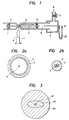
- Figure 1 is an explanatory view showing some of steps of producing a single-polarization optical fiber preform according to the present invention.
- a glass thin film 2 to become a clad is deposited on the inner wall of a glass tube 1 by the ordinary CVD process.
- a glass rod of circular cross section 3 to become a core is inserted into the glass tube, and it is fixed by tools-11 so as to lie centrally of the glass tube 1.
- the glass tube has one end closed, and it is set on a glass lathe (not shown) and is rotated at a fixed speed of rotation. Simultaneously, the tube is heated by a burner 4. At this time, a vacuum tank 5 is disposed at the open part of the glass tube, and the internal pressure of the tube is reduced through a vacuum tube 6 while a vacuum adjusting valve 7 is being regulated. The amount of the pressure reduction is measured by the difference of the levels of a liquid 10 contained in a U-tube 9 one end of which is inserted in the interior 8 of the glass tube.
- the glass layer formed by the CVD process collapses while becoming elliptic, not circular, owing to the minute difference of the wall thickness of the starting quartz tube shown in Figure 2a, etc., and eventually, the optical fiber preform which is solid as shown in Figure 2b is formed.
- the cross-sectional shape of the glass rod 3 for the core need not always be circular, but it may well be elliptic, and a plurality of rods for the core may well be inserted.
- the glass rod to be inserted may well be composed of a core and a clad.
- the rod to be inserted in the case where the rod to be inserted is composed only of the core, it is the clad lower in the refractive index than the core that is deposited in the glass tube 1 by the CVD process, and in the case where the rod to be inserted is composed of the core and the clad, it is a jacket substantially equal in the refractive index to the clad that is deposited in the glass tube 1 by the CVD process.
- Glass having a composition consisting of 15 mol% of B 2 0 3 and 85 mol% of Si0 2 was deposited on the inner wall surface of a quartz tube (18 mm in outside diameter and 15 mm in inside diameter) to a thickness of 180 ⁇ m by the CVD process.
- the resultant quartz tube was heated to 1700 ° C , into a concentric quartz tube having an inside diameter of about 5 mm and an outside diameter of about 11 mm.
- a synthetic quartz glass rod (Sprasil; trade name of Heraus-Schot Co. in West Germany) having an outside diameter of 1 mm was inserted into the quartz tube.
- the optical fiber preform obtained in this example was drawn in well-known fashion, to produce an optical fiber.
- the extinction ratio of the optical fiber for a length of 500 m was measured at a wavelength of 0.633 ⁇ m, it was -30 dB, which verified the excellent polarization holding of the optical fiber.
- Glass having a composition consisting of 15 mol% of B203, 4 mol% of Ge0 2 and 81 mol% of SiO 2 was deposited on the inner wall of the quartz tube described in Example 1, to a thickness of 180 ⁇ m by the CVD process.
- the resultant quartz tube was heated to 1700 °C, into a concentric quartz tube having an inside diameter of 5 mm and an outside diameter of 11 mm.
- a synthetic quartz rod (having a diameter of 2.5 mm and prepared by the VAD (vapor phase axial deposition) process) in a concentric double structure which has a silica glass layer around synthetic quartz having an outside diameter of 1 mm and doped with 10 mol% of Ge0 2 was inserted into the quartz tube.
- the internal pressure of the tube was reduced by 8 mm in terms of the height of water as compared with the atmospheric pressure, and the quartz tube was heated to 1900 °C from outside, under the conditions of 30 r.p.m. in the rotating speed of the tube and 0.25 mm/sec in the moving speed of a burner.
- the quartz tube was made solid to produce an optical fiber preform.
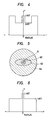
- the optical fiber preform obtained had an outside diameter of about 9.9 mm.
- it had a four-layer cross-sectional structure consisting of a circular core portion 61 doped with Ge0 2 , a circular clad of Si0 2 62, an elliptic jacket 63, and a support of SiO 2 64. Its index profile is shown in Figure 6.
- the optical fiber preform obtained in this example was drawn in well-known fashion into an optical fiber.
- the extinction ratio of the optical fiber for a length of 500 m was measured at a wavelength of 0.633 ⁇ m, it was -35 dB, and excellent polarization holding was exhibited.
- the transmission loss at a wavelength of 1.55 ⁇ m was 0.9 dB/km.
Landscapes
- Chemical & Material Sciences (AREA)
- Engineering & Computer Science (AREA)
- Materials Engineering (AREA)
- Geochemistry & Mineralogy (AREA)
- Manufacturing & Machinery (AREA)
- General Life Sciences & Earth Sciences (AREA)
- Life Sciences & Earth Sciences (AREA)
- Organic Chemistry (AREA)
- Chemical Kinetics & Catalysis (AREA)
- General Chemical & Material Sciences (AREA)
- Manufacture, Treatment Of Glass Fibers (AREA)
- Optical Fibers, Optical Fiber Cores, And Optical Fiber Bundles (AREA)
- Light Guides In General And Applications Therefor (AREA)
- Glass Melting And Manufacturing (AREA)
Applications Claiming Priority (2)
| Application Number | Priority Date | Filing Date | Title |
|---|---|---|---|
| JP179857/82 | 1982-10-15 | ||
| JP57179857A JPS5969438A (ja) | 1982-10-15 | 1982-10-15 | 光フアイバ母材の製造方法 |
Publications (2)
| Publication Number | Publication Date |
|---|---|
| EP0109192A1 true EP0109192A1 (fr) | 1984-05-23 |
| EP0109192B1 EP0109192B1 (fr) | 1986-12-30 |
Family
ID=16073122
Family Applications (1)
| Application Number | Title | Priority Date | Filing Date |
|---|---|---|---|
| EP83306243A Expired EP0109192B1 (fr) | 1982-10-15 | 1983-10-14 | Procédé de fabrication d'une ébauche de fibre optique |
Country Status (5)
| Country | Link |
|---|---|
| US (1) | US4505729A (fr) |
| EP (1) | EP0109192B1 (fr) |
| JP (1) | JPS5969438A (fr) |
| CA (1) | CA1202532A (fr) |
| DE (1) | DE3368592D1 (fr) |
Cited By (3)
| Publication number | Priority date | Publication date | Assignee | Title |
|---|---|---|---|---|
| DE3447081A1 (de) * | 1984-05-26 | 1985-12-19 | AEG-Telefunken Kabelwerke AG, Rheydt, 4050 Mönchengladbach | Verfahren zum herstellen einer vorform zum ziehen von lichtleitfasern |
| GB2284206B (en) * | 1993-11-29 | 1997-11-12 | Samsung Electronics Co Ltd | Optical fibre preforms |
| CN112794639A (zh) * | 2021-03-30 | 2021-05-14 | 藤仓烽火光电材料科技有限公司 | 一种棒外气相沉积的调控方法及设备 |
Families Citing this family (14)
| Publication number | Priority date | Publication date | Assignee | Title |
|---|---|---|---|---|
| DE3447082A1 (de) * | 1984-05-26 | 1985-12-19 | AEG-Telefunken Kabelwerke AG, Rheydt, 4050 Mönchengladbach | Verfahren zum herstellen einer vorform zum ziehen von lichtleitfasern |
| US4749396A (en) * | 1985-01-25 | 1988-06-07 | Polaroid Corporation | Method of forming an optical fiber preform |
| DE3521119A1 (de) * | 1985-06-13 | 1986-12-18 | Heraeus Quarzschmelze Gmbh, 6450 Hanau | Verfahren zur herstellung einer vorform fuer optische fasern und verwendung eines rohres aus quarzglas bzw. dotiertem quarzglas zur herstellung einer solchen vorform |
| CA1317464C (fr) * | 1986-04-28 | 1993-05-11 | William Malcolm Flegal | Methode de recouvrement d'une tige optique preformee, et appareil connexe |
| US4820322A (en) * | 1986-04-28 | 1989-04-11 | American Telephone And Telegraph Company At&T Bell Laboratories | Method of and apparatus for overcladding a glass rod |
| US4750926A (en) * | 1987-08-07 | 1988-06-14 | Corning Glass Works | Method of making precision shaped apertures in glass |
| FR2621035B1 (fr) * | 1987-09-29 | 1992-06-26 | Comp Generale Electricite | Procede de fabrication de fibre optique avec preforme obtenue par retreint |
| US5055120A (en) * | 1987-12-15 | 1991-10-08 | Infrared Fiber Systems, Inc. | Fluoride glass fibers with reduced defects |
| EP0413387A1 (fr) * | 1989-08-16 | 1991-02-20 | Koninklijke Philips Electronics N.V. | Fibre optique en mode simple maintenant la polarisation |
| DE4005730A1 (de) * | 1990-02-23 | 1991-08-29 | Kabelmetal Electro Gmbh | Vorrichtung zur herstellung einer lichtwellenleiter-vorform |
| US5704960A (en) * | 1995-12-20 | 1998-01-06 | Corning, Inc. | Method of forming an optical fiber for reduced polarization effects in amplifiers |
| WO2002098808A1 (fr) * | 2001-05-31 | 2002-12-12 | Corning Incorporated | Procede de fabrication de fibre optique a faible dispersion de polarisation de mode (pmd) |
| JP2004536764A (ja) * | 2001-07-31 | 2004-12-09 | コーニング・インコーポレーテッド | 低偏波モード分散光ファイバ製造方法 |
| US20070062223A1 (en) * | 2006-10-16 | 2007-03-22 | Sterlite Optical Technologies Ltd | Optical fiber having reduced polarization mode dispersion (PMD) and method for producing the same |
Citations (7)
| Publication number | Priority date | Publication date | Assignee | Title |
|---|---|---|---|---|
| US3877912A (en) * | 1973-10-09 | 1975-04-15 | Sumitomo Electric Industries | Method of producing an optical transmission line |
| GB2033372A (en) * | 1978-09-28 | 1980-05-21 | Sumitomo Electric Industries | A Method of Producing an Optical Waveguide |
| GB2043619A (en) * | 1979-03-07 | 1980-10-08 | Standard Telephones Cables Ltd | Optical fibre and optical fibre preform manufacture |
| US4274854A (en) * | 1978-01-13 | 1981-06-23 | Bell Telephone Laboratories, Incorporated | Polarization-preserving optical fiber |
| EP0032390A2 (fr) * | 1980-01-11 | 1981-07-22 | Hitachi, Ltd. | Procédé pour la fabrication d'une préforme pour une fibre optique |
| US4283213A (en) * | 1979-10-22 | 1981-08-11 | International Telephone And Telegraph Corporation | Method of fabrication of single mode optical fibers or waveguides |
| EP0067017A1 (fr) * | 1981-05-29 | 1982-12-15 | Hitachi, Ltd. | Fibre optique qui conserve le plan de la polarisation et procédure de sa fabrication |
Family Cites Families (6)
| Publication number | Priority date | Publication date | Assignee | Title |
|---|---|---|---|---|
| JPS54131043A (en) * | 1978-03-31 | 1979-10-11 | Hitachi Cable Ltd | Production of preform for optical fiber |
| US4184859A (en) * | 1978-06-09 | 1980-01-22 | International Telephone And Telegraph Corporation | Method of fabricating an elliptical core single mode fiber |
| JPS6014321B2 (ja) * | 1981-08-18 | 1985-04-12 | 日立電線株式会社 | 定偏波型光フアイバ |
| US4389229A (en) * | 1981-10-01 | 1983-06-21 | Western Electric Co., Inc. | Methods and apparatus for fabricating a lightguide preform |
| JPS5884137A (ja) * | 1981-11-10 | 1983-05-20 | Nec Corp | 偏光保存光フアイバの製造方法 |
| JPS5918126A (ja) * | 1982-07-20 | 1984-01-30 | Hitachi Cable Ltd | 偏波面保存光フアイバの製造方法 |
-
1982
- 1982-10-15 JP JP57179857A patent/JPS5969438A/ja active Pending
-
1983
- 1983-10-14 DE DE8383306243T patent/DE3368592D1/de not_active Expired
- 1983-10-14 EP EP83306243A patent/EP0109192B1/fr not_active Expired
- 1983-10-14 US US06/542,186 patent/US4505729A/en not_active Expired - Lifetime
- 1983-10-17 CA CA000439139A patent/CA1202532A/fr not_active Expired
Patent Citations (7)
| Publication number | Priority date | Publication date | Assignee | Title |
|---|---|---|---|---|
| US3877912A (en) * | 1973-10-09 | 1975-04-15 | Sumitomo Electric Industries | Method of producing an optical transmission line |
| US4274854A (en) * | 1978-01-13 | 1981-06-23 | Bell Telephone Laboratories, Incorporated | Polarization-preserving optical fiber |
| GB2033372A (en) * | 1978-09-28 | 1980-05-21 | Sumitomo Electric Industries | A Method of Producing an Optical Waveguide |
| GB2043619A (en) * | 1979-03-07 | 1980-10-08 | Standard Telephones Cables Ltd | Optical fibre and optical fibre preform manufacture |
| US4283213A (en) * | 1979-10-22 | 1981-08-11 | International Telephone And Telegraph Corporation | Method of fabrication of single mode optical fibers or waveguides |
| EP0032390A2 (fr) * | 1980-01-11 | 1981-07-22 | Hitachi, Ltd. | Procédé pour la fabrication d'une préforme pour une fibre optique |
| EP0067017A1 (fr) * | 1981-05-29 | 1982-12-15 | Hitachi, Ltd. | Fibre optique qui conserve le plan de la polarisation et procédure de sa fabrication |
Cited By (6)
| Publication number | Priority date | Publication date | Assignee | Title |
|---|---|---|---|---|
| DE3447081A1 (de) * | 1984-05-26 | 1985-12-19 | AEG-Telefunken Kabelwerke AG, Rheydt, 4050 Mönchengladbach | Verfahren zum herstellen einer vorform zum ziehen von lichtleitfasern |
| US4636235A (en) * | 1984-05-26 | 1987-01-13 | Aeg-Telefunken Kabelwerke Ag, Rheydt | Method for producing optical fibers |
| GB2284206B (en) * | 1993-11-29 | 1997-11-12 | Samsung Electronics Co Ltd | Optical fibre preforms |
| US6405566B1 (en) | 1993-11-29 | 2002-06-18 | Samsung Electronics Co., Ltd. | Method and device for over-cladding an optical fiber primary preform |
| CN112794639A (zh) * | 2021-03-30 | 2021-05-14 | 藤仓烽火光电材料科技有限公司 | 一种棒外气相沉积的调控方法及设备 |
| CN112794639B (zh) * | 2021-03-30 | 2021-08-03 | 藤仓烽火光电材料科技有限公司 | 一种棒外气相沉积的调控方法及设备 |
Also Published As
| Publication number | Publication date |
|---|---|
| DE3368592D1 (en) | 1987-02-05 |
| US4505729A (en) | 1985-03-19 |
| JPS5969438A (ja) | 1984-04-19 |
| EP0109192B1 (fr) | 1986-12-30 |
| CA1202532A (fr) | 1986-04-01 |
Similar Documents
| Publication | Publication Date | Title |
|---|---|---|
| EP0032390B1 (fr) | Procédé pour la fabrication d'une préforme pour une fibre optique | |
| EP0109192B1 (fr) | Procédé de fabrication d'une ébauche de fibre optique | |
| US4229070A (en) | High bandwidth optical waveguide having B2 O3 free core and method of fabrication | |
| US4478489A (en) | Polarization retaining single-mode optical waveguide | |
| US4385802A (en) | Long wavelength, low-loss optical waveguide | |
| US4896942A (en) | Polarization-maintaining optical fiber | |
| US4230396A (en) | High bandwidth optical waveguides and method of fabrication | |
| US4339174A (en) | High bandwidth optical waveguide | |
| US4415230A (en) | Polarization retaining single-mode optical waveguide | |
| US4354736A (en) | Stress-induced birefringent single mode optical fiber and a method of fabricating the same | |
| EP0164681B1 (fr) | Fibre optique monomode | |
| US4157906A (en) | Method of drawing glass optical waveguides | |
| EP0061901B1 (fr) | Fibre guide d'onde optique et procédés de formation d'une fibre guide d'onde optique et une préforme d'un guide d'onde optique | |
| US4360371A (en) | Method of making polarization retaining single-mode optical waveguide | |
| EP0198510B1 (fr) | Procédé de fabrication d'une préforme en verre pour fibre optique | |
| US4579571A (en) | Method for fabricating optical fiber preforms | |
| US4500168A (en) | Single polarization optical fibers | |
| US5048923A (en) | Image fiber, image fiber preform, and manufacturing processes thereof | |
| US4838916A (en) | Method for making single-polorization, single mode optical fibers | |
| EP0067017B1 (fr) | Fibre optique qui conserve le plan de la polarisation et procédure de sa fabrication | |
| US6988379B2 (en) | Method of manufacturing large capacity preforms by MCVD | |
| US4351658A (en) | Manufacture of optical fibers | |
| Niizeki | Recent progress in glass fibers for optical communication | |
| US20020000104A1 (en) | Methods of making preform and optical fiber | |
| CA1246875A (fr) | Methode pour eliminer la baisse axiale de l'indice de refraction dans les fibres optiques |
Legal Events
| Date | Code | Title | Description |
|---|---|---|---|
| PUAI | Public reference made under article 153(3) epc to a published international application that has entered the european phase |
Free format text: ORIGINAL CODE: 0009012 |
|
| 17P | Request for examination filed |
Effective date: 19831130 |
|
| AK | Designated contracting states |
Designated state(s): DE FR GB IT NL |
|
| GRAA | (expected) grant |
Free format text: ORIGINAL CODE: 0009210 |
|
| AK | Designated contracting states |
Kind code of ref document: B1 Designated state(s): DE FR GB IT NL |
|
| REF | Corresponds to: |
Ref document number: 3368592 Country of ref document: DE Date of ref document: 19870205 |
|
| ET | Fr: translation filed | ||
| ITF | It: translation for a ep patent filed | ||
| PLBE | No opposition filed within time limit |
Free format text: ORIGINAL CODE: 0009261 |
|
| STAA | Information on the status of an ep patent application or granted ep patent |
Free format text: STATUS: NO OPPOSITION FILED WITHIN TIME LIMIT |
|
| 26N | No opposition filed | ||
| ITTA | It: last paid annual fee | ||
| REG | Reference to a national code |
Ref country code: GB Ref legal event code: IF02 |
|
| PGFP | Annual fee paid to national office [announced via postgrant information from national office to epo] |
Ref country code: FR Payment date: 20020923 Year of fee payment: 20 |
|
| PGFP | Annual fee paid to national office [announced via postgrant information from national office to epo] |
Ref country code: GB Payment date: 20020926 Year of fee payment: 20 |
|
| PGFP | Annual fee paid to national office [announced via postgrant information from national office to epo] |
Ref country code: NL Payment date: 20021003 Year of fee payment: 20 |
|
| PGFP | Annual fee paid to national office [announced via postgrant information from national office to epo] |
Ref country code: DE Payment date: 20021205 Year of fee payment: 20 |
|
| PG25 | Lapsed in a contracting state [announced via postgrant information from national office to epo] |
Ref country code: GB Free format text: LAPSE BECAUSE OF EXPIRATION OF PROTECTION Effective date: 20031013 |
|
| PG25 | Lapsed in a contracting state [announced via postgrant information from national office to epo] |
Ref country code: NL Free format text: LAPSE BECAUSE OF EXPIRATION OF PROTECTION Effective date: 20031014 |
|
| REG | Reference to a national code |
Ref country code: GB Ref legal event code: PE20 |
|
| NLV7 | Nl: ceased due to reaching the maximum lifetime of a patent |
Effective date: 20031014 |