EP0109365B1 - Schutz- und Isolationskappe für Kabelschuhe elektrischer Kabel - Google Patents
Schutz- und Isolationskappe für Kabelschuhe elektrischer Kabel Download PDFInfo
- Publication number
- EP0109365B1 EP0109365B1 EP83830195A EP83830195A EP0109365B1 EP 0109365 B1 EP0109365 B1 EP 0109365B1 EP 83830195 A EP83830195 A EP 83830195A EP 83830195 A EP83830195 A EP 83830195A EP 0109365 B1 EP0109365 B1 EP 0109365B1
- Authority
- EP
- European Patent Office
- Prior art keywords
- electrical cable
- lug
- cap member
- sleeve body
- protecting
- Prior art date
- Legal status (The legal status is an assumption and is not a legal conclusion. Google has not performed a legal analysis and makes no representation as to the accuracy of the status listed.)
- Expired
Links
Images

Classifications
-
- H—ELECTRICITY
- H01—ELECTRIC ELEMENTS
- H01R—ELECTRICALLY-CONDUCTIVE CONNECTIONS; STRUCTURAL ASSOCIATIONS OF A PLURALITY OF MUTUALLY-INSULATED ELECTRICAL CONNECTING ELEMENTS; COUPLING DEVICES; CURRENT COLLECTORS
- H01R13/00—Details of coupling devices of the kinds covered by groups H01R12/70 or H01R24/00 - H01R33/00
- H01R13/46—Bases; Cases
- H01R13/465—Identification means, e.g. labels, tags, markings
-
- H—ELECTRICITY
- H01—ELECTRIC ELEMENTS
- H01R—ELECTRICALLY-CONDUCTIVE CONNECTIONS; STRUCTURAL ASSOCIATIONS OF A PLURALITY OF MUTUALLY-INSULATED ELECTRICAL CONNECTING ELEMENTS; COUPLING DEVICES; CURRENT COLLECTORS
- H01R13/00—Details of coupling devices of the kinds covered by groups H01R12/70 or H01R24/00 - H01R33/00
- H01R13/02—Contact members
- H01R13/10—Sockets for co-operation with pins or blades
- H01R13/11—Resilient sockets
- H01R13/115—U-shaped sockets having inwardly bent legs, e.g. spade type
-
- H—ELECTRICITY
- H01—ELECTRIC ELEMENTS
- H01R—ELECTRICALLY-CONDUCTIVE CONNECTIONS; STRUCTURAL ASSOCIATIONS OF A PLURALITY OF MUTUALLY-INSULATED ELECTRICAL CONNECTING ELEMENTS; COUPLING DEVICES; CURRENT COLLECTORS
- H01R13/00—Details of coupling devices of the kinds covered by groups H01R12/70 or H01R24/00 - H01R33/00
- H01R13/40—Securing contact members in or to a base or case; Insulating of contact members
- H01R13/42—Securing in a demountable manner
- H01R13/422—Securing in resilient one-piece base or case, e.g. by friction; One-piece base or case formed with resilient locking means
Definitions
- the present invention relates to a cap, for protecting and insulating electrical cable lugs.
- cap members for protecting and insulating female lugs for terminating electrical cables which consist of a sleeve body, made of a plastics material, generally polyethylene, effective to be snap engaged onto the contact terminal of the electrical cable.
- cap members in particular, have the further drawback that as they are associated to the female lugs of the electrical cables, they cannot be easily identified, with consequent difficulties in the wiring thereof to terminal boards and electrical apparatus in general.
- cap members because they do not offer the possibility of identifying said electrical cable, after the assembling of the lug, a lot of time is consumed, mainly in the case where the cables are to be numerated at the wiring operations.
- the DE-U-6 938 749 Patent discloses an insulating cap where, because of the necked construction of its inside, the end lug is to be generally affixed to the cable after the introduction of the cable into the cap member, thereby wasting a lot of time, considering the very high number of connections which are to be made, for example in an electric system of a motor vehicle.
- cap cannot be applied to electrical cables already provided at one end with the end lug and having their other end not accessible.
- the task of the present invention is to overcome the abovementioned drawbacks, by providing a cap member, for protecting and insulating electrical lugs, which is effective to be applied in a quick and easy way to a lug in its assembled condition on the cable, while affording the possibility of applying identifying marks to the electrical cable itself.
- Yet another object of the present invention is to provide such a cap member affording the possibility of using fully automatic apparatus, for applying the lugs to the electrical cables, thereby greatly reducing the manufacturing costs.
- Yet another object of the present invention is to provide such a cap member which, owing to the constructional features thereof, is very reliable and safe in operation.
- a cap member for protecting and insulating electrical cable lugs including a sleeve body effective to be slid onto a lug, precoupled to an electrical cable end, comprising, as an extension of said sleeve body, a tubular portion provided for receiving thereon identifying marks of said elec-- trical cable, characterized in that said sleeve body is provided, in its inside, with a projection for snap engaging said lug in its precoupled or crimped condition to said electrical cable, and with an abutment edge for locking said lug inside said sleeve body, and in that said identifying mark receiving portion is included between an annular forward projection having a lead-in slanted surface and a further annular rear projection spaced a given distance from said front projection.
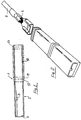
- the cap member for protecting and insulating electrical cable lugs which is overally indicated at the reference number 1, comprises a sleeve body 2 provided with means, consisting of a projection 3, effective to afford the possibility of snap engaging a female lug 4, in its coupled or crimped condition to an electrical cable 5.
- the sleeve body 2 is provided with an abutment edge 6, for locking the lug inside said sleeve body 2.
- a main feature of the invention is that, as an extension of said sleeve body 2, there is provided, in a single piece, a tubular portion 10 which, on its outer side surface, is provided with a region encompassed by an annular projection 11, having a lead-in slanted surface 12 and an end projection 13.
- the region defined between the two projections 11 and 13 affords the possibility, in actual practice, of housing identifying marks for said electrical cable 5.
- said identifying marks which may consist of numbers, letters or symbols of any types, are provided on small bands 20 effective to be associated with the outer surface of the cap member 1 and caused to slide in such a way as to be housed in the region defined by said projections 11 and 13 therefrom they cannot disengage owing to the provision of said projections.
- the tubular portion 10 in addition to increasing the working surface of the cap member, thereby affording the possibility of placing said identifying marks onto said cap member, also provides an identifying mark holding region, said identifying marks being advantageously applied on said bands 20 made of a comparatively resilient material, to be resiliently slid onto said cap in such a way as to slide to the region defined by said projections 11 and 13.
- the cap member according to the invention affords the advantage of great economical savings, since it affords the possibility of cutting the wires, removing the insulating material and applying the lug in a fully automatic manner.
- the used material for making the cap member as well as the size and specific shape may be any according to the needs, though the best results have been obtained by using an insulating plastics material.
Landscapes
- Cable Accessories (AREA)
- Organic Insulating Materials (AREA)
- Insulating Bodies (AREA)
- Connections Effected By Soldering, Adhesion, Or Permanent Deformation (AREA)
Claims (1)
- Schutz- und Isolationskappe für Kabelschuhe elektrischer Kabel, mit einem Muffenstück (2), welcher auf einen, einem Ende des elektrischen Kabels vorgekoppelten Kabelschuh (4) aufgeschoben werden kann, und als Verlängerung des Muffenstücks einem rohrförmigen Abschnitt zur Aufnahme auf denselben von Identifizierungsmarkierungen (20) für das elektrische Kabel, dadurch gekennzeichnet, daß das Muffenstück (2) in seinem Inneren mit einem Vorsprung (3) für den Schnappeingriff mit dem Kabelschuh (4) in dessen mit dem elektrischen Kabel (5) vorgekoppeltem oder auf diesem aufgeschrumpeltem Zustand und mit einem Anschlagrand (6) zur Befestigung des Kabelschuhes innerhalb des Muffenstücks (2) versehen ist und daß der die Identifizierungsmarkierung aufnehmende Abschnitt zwischen einem ringförmigen, eine abgeschrägte Einzugsfläche (12) aufweisenden Vordervorsprung (11) und einem weiteren ringförmigen, an einem vorgegebenen Abstand vom Vordervorsprung (11) angeordneten Hintervorsprung (13) eingeschlossen ist.
Priority Applications (1)
| Application Number | Priority Date | Filing Date | Title |
|---|---|---|---|
| AT83830195T ATE26196T1 (de) | 1982-10-18 | 1983-10-07 | Schutz- und isolationskappe fuer kabelschuhe elektrischer kabel. |
Applications Claiming Priority (2)
| Application Number | Priority Date | Filing Date | Title |
|---|---|---|---|
| IT2322382U | 1982-10-18 | ||
| ITMI1982U23223U IT8223223U1 (it) | 1982-10-18 | 1982-10-18 | Cappuccio, per la protezione e l'isolamento dei capi corda di cavi elettrici. |
Publications (2)
| Publication Number | Publication Date |
|---|---|
| EP0109365A1 EP0109365A1 (de) | 1984-05-23 |
| EP0109365B1 true EP0109365B1 (de) | 1987-03-25 |
Family
ID=11205062
Family Applications (1)
| Application Number | Title | Priority Date | Filing Date |
|---|---|---|---|
| EP83830195A Expired EP0109365B1 (de) | 1982-10-18 | 1983-10-07 | Schutz- und Isolationskappe für Kabelschuhe elektrischer Kabel |
Country Status (4)
| Country | Link |
|---|---|
| EP (1) | EP0109365B1 (de) |
| AT (1) | ATE26196T1 (de) |
| DE (1) | DE3370568D1 (de) |
| IT (1) | IT8223223U1 (de) |
Families Citing this family (2)
| Publication number | Priority date | Publication date | Assignee | Title |
|---|---|---|---|---|
| US5470253A (en) * | 1994-10-03 | 1995-11-28 | Caterpillar Inc. | Engine wiring system |
| US5529513A (en) * | 1994-12-22 | 1996-06-25 | Monster Cable International, Ltd. | Cable connector having removable coded rings |
Family Cites Families (3)
| Publication number | Priority date | Publication date | Assignee | Title |
|---|---|---|---|---|
| US3460700A (en) * | 1967-08-21 | 1969-08-12 | Cascade Corp | Side-shift apparatus for a lift truck |
| DE6938749U (de) * | 1969-10-03 | 1970-01-15 | Wieland Elek Sche Ind Gmbh Fa | Elektrischer flachstecker |
| DE2829620C2 (de) * | 1978-07-06 | 1983-06-30 | Wago-Kontakttechnik Gmbh, 4950 Minden | Bezeichnungsschilderstreifen für die Kennzeichnung insbesondere von Reihenklemmen |
-
1982
- 1982-10-18 IT ITMI1982U23223U patent/IT8223223U1/it unknown
-
1983
- 1983-10-07 AT AT83830195T patent/ATE26196T1/de not_active IP Right Cessation
- 1983-10-07 DE DE8383830195T patent/DE3370568D1/de not_active Expired
- 1983-10-07 EP EP83830195A patent/EP0109365B1/de not_active Expired
Also Published As
| Publication number | Publication date |
|---|---|
| ATE26196T1 (de) | 1987-04-15 |
| IT8223223U1 (it) | 1984-04-18 |
| EP0109365A1 (de) | 1984-05-23 |
| IT8223223V0 (it) | 1982-10-18 |
| DE3370568D1 (en) | 1987-04-30 |
Similar Documents
| Publication | Publication Date | Title |
|---|---|---|
| US5429529A (en) | Structure for connecting shielded-cable end | |
| US3721945A (en) | Integrated wire termination system with integral retainer | |
| US4690481A (en) | Coaxial coupling | |
| US3848954A (en) | Clip terminal and applicator tool combination | |
| EP0378581B1 (de) | Abziehanordnung | |
| US6254430B1 (en) | Coaxial connector | |
| US6086413A (en) | Multiple wire connector | |
| US4474420A (en) | Electrical connector for flexible printed circuits | |
| ES2002742A6 (es) | Faro para vehiculo automovil | |
| US4797112A (en) | Wire holders and harnesses incorporating wire holders | |
| CA1138549A (en) | Electrical connector | |
| US3800267A (en) | Lamp socket | |
| US4167299A (en) | Electrical receptacle with releasable tab latching means | |
| US3654594A (en) | Crimp type terminal | |
| US4218109A (en) | Electrical connector assembly | |
| ES8800794A1 (es) | Dispositivo para conectar a contactos de conexion de corte y traccion, hilos de cable. | |
| US3577119A (en) | Electrical connectors on a carrier strip | |
| GB2093641A (en) | Improvements in or relating to electrical contacts | |
| US4409713A (en) | Electrical connector application tool | |
| US2748367A (en) | Electrical connector | |
| EP0109365A1 (de) | Schutz- und Isolationskappe für Kabelschuhe elektrischer Kabel | |
| US4796358A (en) | Method and apparatus for assembly of electrical cable | |
| US2592788A (en) | Wire terminal and insulating sleeve | |
| EP0634820B1 (de) | Verbindervorrichtung für elektrische Bauteile | |
| US3843050A (en) | In-line fuse holder |
Legal Events
| Date | Code | Title | Description |
|---|---|---|---|
| PUAI | Public reference made under article 153(3) epc to a published international application that has entered the european phase |
Free format text: ORIGINAL CODE: 0009012 |
|
| AK | Designated contracting states |
Designated state(s): AT BE CH DE FR GB LI NL SE |
|
| 17P | Request for examination filed |
Effective date: 19841009 |
|
| GRAA | (expected) grant |
Free format text: ORIGINAL CODE: 0009210 |
|
| AK | Designated contracting states |
Kind code of ref document: B1 Designated state(s): AT BE CH DE FR GB LI NL SE |
|
| PG25 | Lapsed in a contracting state [announced via postgrant information from national office to epo] |
Ref country code: SE Effective date: 19870325 Ref country code: NL Effective date: 19870325 Ref country code: BE Effective date: 19870325 Ref country code: AT Effective date: 19870325 |
|
| REF | Corresponds to: |
Ref document number: 26196 Country of ref document: AT Date of ref document: 19870415 Kind code of ref document: T |
|
| REF | Corresponds to: |
Ref document number: 3370568 Country of ref document: DE Date of ref document: 19870430 |
|
| ET | Fr: translation filed | ||
| NLV1 | Nl: lapsed or annulled due to failure to fulfill the requirements of art. 29p and 29m of the patents act | ||
| PLBE | No opposition filed within time limit |
Free format text: ORIGINAL CODE: 0009261 |
|
| STAA | Information on the status of an ep patent application or granted ep patent |
Free format text: STATUS: NO OPPOSITION FILED WITHIN TIME LIMIT |
|
| 26N | No opposition filed | ||
| PG25 | Lapsed in a contracting state [announced via postgrant information from national office to epo] |
Ref country code: GB Effective date: 19881007 |
|
| PG25 | Lapsed in a contracting state [announced via postgrant information from national office to epo] |
Ref country code: LI Effective date: 19881031 Ref country code: CH Effective date: 19881031 |
|
| PG25 | Lapsed in a contracting state [announced via postgrant information from national office to epo] |
Ref country code: FR Free format text: LAPSE BECAUSE OF NON-PAYMENT OF DUE FEES Effective date: 19890630 |
|
| REG | Reference to a national code |
Ref country code: CH Ref legal event code: PL |
|
| PG25 | Lapsed in a contracting state [announced via postgrant information from national office to epo] |
Ref country code: DE Effective date: 19890701 |
|
| GBPC | Gb: european patent ceased through non-payment of renewal fee | ||
| REG | Reference to a national code |
Ref country code: FR Ref legal event code: ST |