EP0109369A2 - Schneidvorrichtung - Google Patents
Schneidvorrichtung Download PDFInfo
- Publication number
- EP0109369A2 EP0109369A2 EP83850218A EP83850218A EP0109369A2 EP 0109369 A2 EP0109369 A2 EP 0109369A2 EP 83850218 A EP83850218 A EP 83850218A EP 83850218 A EP83850218 A EP 83850218A EP 0109369 A2 EP0109369 A2 EP 0109369A2
- Authority
- EP
- European Patent Office
- Prior art keywords
- axis
- cutting
- sleeve member
- radially
- tool
- Prior art date
- Legal status (The legal status is an assumption and is not a legal conclusion. Google has not performed a legal analysis and makes no representation as to the accuracy of the status listed.)
- Granted
Links
Images
Classifications
-
- B—PERFORMING OPERATIONS; TRANSPORTING
- B23—MACHINE TOOLS; METAL-WORKING NOT OTHERWISE PROVIDED FOR
- B23B—TURNING; BORING
- B23B29/00—Holders for non-rotary cutting tools; Boring bars or boring heads; Accessories for tool holders
- B23B29/03—Boring heads
- B23B29/034—Boring heads with tools moving radially, e.g. for making chamfers or undercuttings
- B23B29/03403—Boring heads with tools moving radially, e.g. for making chamfers or undercuttings radially adjustable before starting manufacturing
- B23B29/03428—Boring heads with tools moving radially, e.g. for making chamfers or undercuttings radially adjustable before starting manufacturing by means of an eccentric
-
- B—PERFORMING OPERATIONS; TRANSPORTING
- B23—MACHINE TOOLS; METAL-WORKING NOT OTHERWISE PROVIDED FOR
- B23B—TURNING; BORING
- B23B2260/00—Details of constructional elements
- B23B2260/088—Indication scales
-
- Y—GENERAL TAGGING OF NEW TECHNOLOGICAL DEVELOPMENTS; GENERAL TAGGING OF CROSS-SECTIONAL TECHNOLOGIES SPANNING OVER SEVERAL SECTIONS OF THE IPC; TECHNICAL SUBJECTS COVERED BY FORMER USPC CROSS-REFERENCE ART COLLECTIONS [XRACs] AND DIGESTS
- Y10—TECHNICAL SUBJECTS COVERED BY FORMER USPC
- Y10T—TECHNICAL SUBJECTS COVERED BY FORMER US CLASSIFICATION
- Y10T408/00—Cutting by use of rotating axially moving tool
- Y10T408/83—Tool-support with means to move Tool relative to tool-support
- Y10T408/85—Tool-support with means to move Tool relative to tool-support to move radially
- Y10T408/854—Tool-support with means to move Tool relative to tool-support to move radially to move eccentrically mounted Tool
-
- Y—GENERAL TAGGING OF NEW TECHNOLOGICAL DEVELOPMENTS; GENERAL TAGGING OF CROSS-SECTIONAL TECHNOLOGIES SPANNING OVER SEVERAL SECTIONS OF THE IPC; TECHNICAL SUBJECTS COVERED BY FORMER USPC CROSS-REFERENCE ART COLLECTIONS [XRACs] AND DIGESTS
- Y10—TECHNICAL SUBJECTS COVERED BY FORMER USPC
- Y10T—TECHNICAL SUBJECTS COVERED BY FORMER US CLASSIFICATION
- Y10T408/00—Cutting by use of rotating axially moving tool
- Y10T408/83—Tool-support with means to move Tool relative to tool-support
- Y10T408/85—Tool-support with means to move Tool relative to tool-support to move radially
- Y10T408/854—Tool-support with means to move Tool relative to tool-support to move radially to move eccentrically mounted Tool
- Y10T408/855—Tool-support including plural, adjustable sections
-
- Y—GENERAL TAGGING OF NEW TECHNOLOGICAL DEVELOPMENTS; GENERAL TAGGING OF CROSS-SECTIONAL TECHNOLOGIES SPANNING OVER SEVERAL SECTIONS OF THE IPC; TECHNICAL SUBJECTS COVERED BY FORMER USPC CROSS-REFERENCE ART COLLECTIONS [XRACs] AND DIGESTS
- Y10—TECHNICAL SUBJECTS COVERED BY FORMER USPC
- Y10T—TECHNICAL SUBJECTS COVERED BY FORMER US CLASSIFICATION
- Y10T408/00—Cutting by use of rotating axially moving tool
- Y10T408/83—Tool-support with means to move Tool relative to tool-support
- Y10T408/85—Tool-support with means to move Tool relative to tool-support to move radially
- Y10T408/858—Moving means including wedge, screw or cam
- Y10T408/859—Rotary cam
- Y10T408/8592—Coaxial with tool-axis
Definitions
- the present invention relates to a device for radial adjustment of a cutting insert in rotary cutting tools for chipforming machining of preferably metallic workpieces, wherein the cutting insert is provided on a tool element, such as a drill or a shank end mill, which is mounted in a tool holder, comprising a sleeve member which is arranged rotatably between the tool holder and the tool element, said sleeve member being rotatable relative to the tool holder about a first axis and relative to the tool element about a second axis, said second axis being radially spaced from said first axis, thereby causing the tool element and thus also the cutting insert to be displaced radially relative to the tool holder upon rotation of the sleeve member relative to the tool element and the tool holder.
- a tool element such as a drill or a shank end mill
- the object of the present invention is to provide a device of the above type in which cutting tools having centre inserts can be radially displaced without jeopardizing the function of the cutting tool.
- Another object of the invention is to provide a radial adjustment of the cutting insert as accurate as possible.
- a further object of the invention is to provide a device in which the length of the tool holder is no larger than that of tool holders for tool elements which do not allow radial adjustment of the cutting insert.
- a still further object of the invention is to provide a device in which the unbalanced forces created by radial adjustment of the cutting insert are as small as possible.
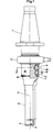
- a tool element 10 in form of a short hole drill is shown, which is mounted in a tool holder 11.
- the tool holder 11 is in conventional manner intended to be mounted in a conical bore in a machine spindle, not shown.
- a swivel 12 is mounted on the tool holder 11 for supplying cooling and flushing fluid to the drill 10.
- the swivel 12 is of the type described in US-A-4 293 251.
- the drill 10 is provided with a radially inner cutting insert 13 and a radially outer cutting insert 14.
- the drill 10 is in conventional manner secured to the tool holder 11 by means of screws 15, 16 which rest against planar surfaces 25, 26 on a bevelled portion of the drill 10.
- a sleeve member 17 is rotatably mounted between the tool holder 11 and the drill 10.
- the sleeve member 17 is rotatable relative to the tool holder 11 about an axis 18 and relative to the drill 10 about an axis 19.
- the axis 19 is radially spaced from the axis 18.
- the axis 19 coincides with the rotational axis 21 of the drill 10 in one rotational position of the sleeve nember 17.
- the axes 19 and 21 coincide when the sleeve member 17 is set such that the drill 10 drills a hole having nominal diameter.
- the sleeve member 17, thus, has mutually eccentric inner and outer surfaces and is outwardly, i.e. along its outer surface, rotatable about the axis 18 and inwardly, i.e. along its inner surface, rotatable about the axis 19.
- the axis 19 is located in front of the axis 18, when seen in the cutting direction of the cutting insert 13, and the axis 18 is located radially outwardly of the axis 19 with respect to the rotational axis 21.
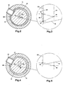
- the insert 13 and the outer insert 14, now shown will be moved from the radially outer position shown in Fig. 3 to the radially inner position shown in Fig. 5.
- the radially outer position relates to a position of the inserts in which larger hole diameter is obtained than in the radially inner position.
- movement radially inwards of the insert relates to an adjustment for decreasing the hole diameter.
- the insert 13 extends further radially outwards in the above-defined radially inner position than in the radially outer position.
- the above movement of the inserts is illustrated in Fig. 3 which shows how the axis 19 moves along an arc 20 having the axis 18 as its centre from the position 19' to the position 19"; the axis 19 being fixed relative to the drill 10. If the drill 10 did follow the rotation of the sleeve member 17 then all points on the cutting edge 22 of the insert 13 would move along arcs parallel with the arc 20 upon rotation of the sleeve member 17.
- the direction of the cutting edge 22 shall be maintained unchanged when the rotation of the sleeve member 17 is terminated.
- the drill 10, and thus its inserts shall be rotated in counter clockwise direction about the axis 19.
- the maintenance of an unchanged direction of the cutting edge 22 upon terminated rotation of the sleeve member 17 is ensured by means of the screws 15, 16. Practically, before rotating the sleeve A the screws 15, 16 are loosened so that the drill 10 can be maintained in an unchanged rotational position during the adjustment of the bore diameter.
- the eccentricity of the sleeve member 17 is disposed in such a way relative to the axes 19, 21, i.e. the axes 18, 19, 21 are mutually located in such a way, that the cutting edge 22 is more remote from a plane 23, which passes through the axis 18 and which is parallel with the cutting edge 22, in an intermediate position than in its radially outermost and innermost positions when the insert 13 upon rotation of the sleeve member 17 is moved from its radially outermost position, compare Fig. 3, to its radially innermost position, compare Fig. 5.
- This means that the two positions 19', 19" of the axis 19 are located at different sides of a plane extending through the axis 18 and being perpendicular to the plane 23.
- the cutting edge of this insert is normally disposed somewhat behind, when seen in the rotational direction, a plane which extends through the rotational axis and is parallel with the cutting edge.
- the radially inner insert 13 is usually located in such a way that its cutting edge 22 is disposed behind a plane 24 which extends through the rotational axis 21 in parallelism with the cutting edge 22, when seen in the rotational direction of the drill.
- the cutting edge 22 Due to the fact that the displacement of the cutting edge 22 toward the plane 24 is small, in the order of 0,03 mm, and since the cutting edge 22 is disposed behind the plane 24 about 0,1 mm, the cutting edge 22 will constantly be located between the plane 23 and the plane 24 when the insert 13 is moved from its radially outermost to its radially innermost position.
- the cutting edge 22 is at the same distance from the plane 24 as when the inserts are at the said nominal position.
- the inserts 13, 14 can be moved further radially inwards - the total movement being in the order of 2 mm - without jeopardizing the function of the drill.
- the cutting edge 22 can also be moved radially outwards in the order of 0,4 mm from its position at nominal drilling diameter.
- the sleeve member 17 For purposes of limiting the rotation of the sleeve member 17 the latter is provided with a slot. The opposed end surfaces of this slot provide stop means for the rotation of the sleeve member 17 by cooperation with a stop member in form of the screw 15.
- the generated unbalanced forces are small, since only the drill 10 and thus not the sleeve member 17, is displaced relative to the rotational axis of the drill.
- the tool holder 11 and a radial flange 28 on the sleeve member 17 are provided with indicating means for indication of mutual rotational position. According to-the invention it is possible to adjust the diameter of the drill with an accuracy of + 0,02 mm. Further, the overall length of the tool holder 11 does not need to be larger than the length of corresponding tool holders for drills which are not radially adjustable.
- the invention is shown applied on a short hole drill.
- the invention can of course be applied on other types of rotary cutting tools, for instance drilling shank end mills.
- the invention can be used in connection with different types of tool holders, for instance holders in form of an adapter which is secured to an arbor which in its turn is connected to the machine spindle.
Landscapes
- Engineering & Computer Science (AREA)
- Mechanical Engineering (AREA)
- Cutting Tools, Boring Holders, And Turrets (AREA)
- Jigs For Machine Tools (AREA)
- Drilling Tools (AREA)
Applications Claiming Priority (2)
| Application Number | Priority Date | Filing Date | Title |
|---|---|---|---|
| SE8206434 | 1982-11-12 | ||
| SE8206434A SE464012B (sv) | 1982-11-12 | 1982-11-12 | Anordning foer radialinstaellning av ett skaer |
Publications (3)
| Publication Number | Publication Date |
|---|---|
| EP0109369A2 true EP0109369A2 (de) | 1984-05-23 |
| EP0109369A3 EP0109369A3 (en) | 1985-10-02 |
| EP0109369B1 EP0109369B1 (de) | 1988-10-26 |
Family
ID=20348560
Family Applications (1)
| Application Number | Title | Priority Date | Filing Date |
|---|---|---|---|
| EP83850218A Expired EP0109369B1 (de) | 1982-11-12 | 1983-08-19 | Schneidvorrichtung |
Country Status (7)
| Country | Link |
|---|---|
| US (1) | US4679972A (de) |
| EP (1) | EP0109369B1 (de) |
| JP (1) | JPS59107807A (de) |
| BR (1) | BR8304650A (de) |
| CA (1) | CA1231228A (de) |
| DE (1) | DE3378306D1 (de) |
| SE (1) | SE464012B (de) |
Cited By (4)
| Publication number | Priority date | Publication date | Assignee | Title |
|---|---|---|---|---|
| FR2618359A1 (fr) * | 1987-07-20 | 1989-01-27 | Kaiser Heinz Ag | Dispositif d'alesage au tour a largeur d'alesage reglable |
| EP0325212A3 (de) * | 1988-01-19 | 1991-01-09 | ENTWICKLUNGSZENTRUM FÜR ZERSPANUNGSTECHNIK GMBH & CO. KG | Messerkopf |
| WO1994002275A1 (de) * | 1992-07-27 | 1994-02-03 | Koyemann Werkzeuge Gmbh & Co. | Radial einstellbares werkzeugkopf, insbesondere fur dreh- und ausbohroperationen |
| EP0618028A1 (de) * | 1993-03-29 | 1994-10-05 | Widia GmbH | Vorrichtung mit einem in einem Halter eingespannten und radial verschieblichen Zapfen oder Schaft |
Families Citing this family (6)
| Publication number | Priority date | Publication date | Assignee | Title |
|---|---|---|---|---|
| JPH0347774Y2 (de) * | 1985-08-08 | 1991-10-11 | ||
| US20050074305A1 (en) * | 2003-10-06 | 2005-04-07 | Hsin-Tien Chang | Micro-adjustable boring bar |
| US7455487B2 (en) * | 2006-01-17 | 2008-11-25 | Hsin-Tien Chang | Gyration balancing calibration free high-speed boring tool |
| WO2007121664A1 (en) * | 2006-04-18 | 2007-11-01 | Shoushan Qiu | A fine adjusting method of the feed amount of the boring cutter and the adjusting device thereof |
| US7699567B2 (en) * | 2006-11-07 | 2010-04-20 | Sandvik, Inc. | Final adjustment mechanism with tactile feedback |
| CN101450447B (zh) * | 2007-11-30 | 2012-06-13 | 上海诺玛液压系统有限公司 | 用于电液伺服阀阀套的偏心外圆的加工夹套 |
Family Cites Families (12)
| Publication number | Priority date | Publication date | Assignee | Title |
|---|---|---|---|---|
| US2849902A (en) * | 1955-11-18 | 1958-09-02 | De Vlieg Machine Co | Presetting boring bar and tool holder |
| US2991667A (en) * | 1958-07-23 | 1961-07-11 | Williams Judson | Boring tool |
| US3000240A (en) * | 1960-06-06 | 1961-09-19 | Eckardt Frederick Helmut | Eccentrically adjustable tool holder |
| US3125903A (en) * | 1960-10-26 | 1964-03-24 | Briney Mfg Co | Eccentric boring head |
| DE1477405C3 (de) * | 1964-04-17 | 1974-03-07 | Karl Hueller Gmbh, 7140 Ludwigsburg | Einstellvorrichtung für Werkzeugträger, insbesondere für Bohrstangen von Feinbohrmaschinen mit einer drehbaren Bohrspindel |
| DE2014690A1 (de) * | 1970-03-26 | 1971-11-04 | Emw Elektro Motoren Feinbauwer | Nuteneinstechgerät |
| US3689169A (en) * | 1970-08-28 | 1972-09-05 | Richard C Gersch | Adjustable tool block assembly |
| SU475221A2 (ru) * | 1973-07-03 | 1975-06-30 | Одесское специальное конструкторское бюро специальных станков | Расточна оправка |
| DE2500748C3 (de) * | 1975-01-10 | 1978-09-14 | Wikotool-Systemtechnik Maschinenbau Gmbh U. Co Kg, 4811 Leopoldshoehe | Spindelstock |
| US4053252A (en) * | 1976-05-05 | 1977-10-11 | Gersch Richard C | Cutting tool holder |
| JPS542433A (en) * | 1977-06-03 | 1979-01-10 | Toyotsuu Denshi Kk | Drive circuit for yarn feder |
| US4439074A (en) * | 1982-06-30 | 1984-03-27 | Ex-Cell-O Corporation | Boring tool with coarse and fine adjustment |
-
1982
- 1982-11-12 SE SE8206434A patent/SE464012B/sv not_active IP Right Cessation
-
1983
- 1983-08-19 DE DE8383850218T patent/DE3378306D1/de not_active Expired
- 1983-08-19 EP EP83850218A patent/EP0109369B1/de not_active Expired
- 1983-08-24 US US06/526,078 patent/US4679972A/en not_active Expired - Lifetime
- 1983-08-29 BR BR8304650A patent/BR8304650A/pt unknown
- 1983-08-29 CA CA000435527A patent/CA1231228A/en not_active Expired
- 1983-10-18 JP JP58193558A patent/JPS59107807A/ja active Granted
Cited By (4)
| Publication number | Priority date | Publication date | Assignee | Title |
|---|---|---|---|---|
| FR2618359A1 (fr) * | 1987-07-20 | 1989-01-27 | Kaiser Heinz Ag | Dispositif d'alesage au tour a largeur d'alesage reglable |
| EP0325212A3 (de) * | 1988-01-19 | 1991-01-09 | ENTWICKLUNGSZENTRUM FÜR ZERSPANUNGSTECHNIK GMBH & CO. KG | Messerkopf |
| WO1994002275A1 (de) * | 1992-07-27 | 1994-02-03 | Koyemann Werkzeuge Gmbh & Co. | Radial einstellbares werkzeugkopf, insbesondere fur dreh- und ausbohroperationen |
| EP0618028A1 (de) * | 1993-03-29 | 1994-10-05 | Widia GmbH | Vorrichtung mit einem in einem Halter eingespannten und radial verschieblichen Zapfen oder Schaft |
Also Published As
| Publication number | Publication date |
|---|---|
| EP0109369B1 (de) | 1988-10-26 |
| DE3378306D1 (en) | 1988-12-01 |
| JPH0561042B2 (de) | 1993-09-03 |
| US4679972A (en) | 1987-07-14 |
| SE464012B (sv) | 1991-02-25 |
| SE8206434D0 (sv) | 1982-11-12 |
| SE8206434L (sv) | 1984-05-13 |
| JPS59107807A (ja) | 1984-06-22 |
| BR8304650A (pt) | 1984-11-06 |
| EP0109369A3 (en) | 1985-10-02 |
| CA1231228A (en) | 1988-01-12 |
Similar Documents
| Publication | Publication Date | Title |
|---|---|---|
| US5816753A (en) | Port cutting tool with multiple function inserts | |
| KR100548094B1 (ko) | 정면밀링커터 | |
| US4606680A (en) | Reamer core drill with cutting bits | |
| US4318647A (en) | Adjustable insert seat and wedge assembly for an indexable boring cutter | |
| US5071295A (en) | Cutters | |
| US4149821A (en) | Radially balanced rotary drill | |
| EP1152858B1 (de) | Werkzeug und schneidkopf für spanabhebende bearbeitung | |
| EP0059513B1 (de) | Vorrichtung zum Befestigen von Schneidwerkzeugen | |
| US6206616B1 (en) | Tool and method for cutting a circular opening and retaining the cut portion | |
| JPH06507580A (ja) | 穿孔工具 | |
| US5906458A (en) | Reamer with clamping arrangement for adjustable cutting insert | |
| EP0997216A2 (de) | Fräser | |
| EP0109369B1 (de) | Schneidvorrichtung | |
| GB2165472A (en) | Cutting tool | |
| US3782848A (en) | Combination expandable cutting and seating tool | |
| US5863161A (en) | Countersinking tool with removable cutting inserts | |
| US4097181A (en) | Rotary cutting tool | |
| SE438807B (sv) | Borr med utbytbart sker | |
| US4634324A (en) | Tool holder with radial adjustment means for a tool, in particular a rotary tool | |
| US4580934A (en) | Hole sizing tool | |
| WO1987000100A1 (en) | Adjustable length chamfering tool | |
| US2477153A (en) | Milling tool | |
| US20020067961A1 (en) | Cutting tool | |
| US3097548A (en) | Adjustable boring head | |
| US2395628A (en) | Drilling and milling device |
Legal Events
| Date | Code | Title | Description |
|---|---|---|---|
| PUAI | Public reference made under article 153(3) epc to a published international application that has entered the european phase |
Free format text: ORIGINAL CODE: 0009012 |
|
| AK | Designated contracting states |
Designated state(s): DE FR GB IT |
|
| 17P | Request for examination filed |
Effective date: 19840626 |
|
| PUAL | Search report despatched |
Free format text: ORIGINAL CODE: 0009013 |
|
| AK | Designated contracting states |
Designated state(s): DE FR GB IT |
|
| 17Q | First examination report despatched |
Effective date: 19870212 |
|
| ITF | It: translation for a ep patent filed | ||
| GRAA | (expected) grant |
Free format text: ORIGINAL CODE: 0009210 |
|
| AK | Designated contracting states |
Kind code of ref document: B1 Designated state(s): DE FR GB IT |
|
| REF | Corresponds to: |
Ref document number: 3378306 Country of ref document: DE Date of ref document: 19881201 |
|
| ET | Fr: translation filed | ||
| PLBE | No opposition filed within time limit |
Free format text: ORIGINAL CODE: 0009261 |
|
| STAA | Information on the status of an ep patent application or granted ep patent |
Free format text: STATUS: NO OPPOSITION FILED WITHIN TIME LIMIT |
|
| 26N | No opposition filed | ||
| ITTA | It: last paid annual fee | ||
| REG | Reference to a national code |
Ref country code: GB Ref legal event code: IF02 |
|
| PGFP | Annual fee paid to national office [announced via postgrant information from national office to epo] |
Ref country code: FR Payment date: 20020808 Year of fee payment: 20 |
|
| PGFP | Annual fee paid to national office [announced via postgrant information from national office to epo] |
Ref country code: GB Payment date: 20020814 Year of fee payment: 20 |
|
| PGFP | Annual fee paid to national office [announced via postgrant information from national office to epo] |
Ref country code: DE Payment date: 20020829 Year of fee payment: 20 |
|
| PG25 | Lapsed in a contracting state [announced via postgrant information from national office to epo] |
Ref country code: GB Free format text: LAPSE BECAUSE OF EXPIRATION OF PROTECTION Effective date: 20030818 |
|
| REG | Reference to a national code |
Ref country code: GB Ref legal event code: PE20 |