EP0109378A1 - Dispositif pour usiner le fond de profil des filetages - Google Patents
Dispositif pour usiner le fond de profil des filetages Download PDFInfo
- Publication number
- EP0109378A1 EP0109378A1 EP83890132A EP83890132A EP0109378A1 EP 0109378 A1 EP0109378 A1 EP 0109378A1 EP 83890132 A EP83890132 A EP 83890132A EP 83890132 A EP83890132 A EP 83890132A EP 0109378 A1 EP0109378 A1 EP 0109378A1
- Authority
- EP
- European Patent Office
- Prior art keywords
- tool
- roller
- axis
- tool holder
- rotation
- Prior art date
- Legal status (The legal status is an assumption and is not a legal conclusion. Google has not performed a legal analysis and makes no representation as to the accuracy of the status listed.)
- Withdrawn
Links
- 238000003754 machining Methods 0.000 claims description 5
- 239000011295 pitch Substances 0.000 description 9
- 230000000712 assembly Effects 0.000 description 7
- 238000000429 assembly Methods 0.000 description 7
- 238000005096 rolling process Methods 0.000 description 5
- 238000006073 displacement reaction Methods 0.000 description 3
- 230000006978 adaptation Effects 0.000 description 1
- 238000006243 chemical reaction Methods 0.000 description 1
- 238000010276 construction Methods 0.000 description 1
- 230000007812 deficiency Effects 0.000 description 1
- 239000003208 petroleum Substances 0.000 description 1
- 230000036316 preload Effects 0.000 description 1
Images

Classifications
-
- B—PERFORMING OPERATIONS; TRANSPORTING
- B21—MECHANICAL METAL-WORKING WITHOUT ESSENTIALLY REMOVING MATERIAL; PUNCHING METAL
- B21H—MAKING PARTICULAR METAL OBJECTS BY ROLLING, e.g. SCREWS, WHEELS, RINGS, BARRELS, BALLS
- B21H3/00—Making helical bodies or bodies having parts of helical shape
- B21H3/02—Making helical bodies or bodies having parts of helical shape external screw-threads ; Making dies for thread rolling
- B21H3/04—Making by means of profiled-rolls or die rolls
Definitions
- the invention relates to a device for machining the profile base of threads, consisting of a tool holder receiving a roller tool and extending essentially in the direction of the axis of rotation of the roller tool, which is mounted on a tool holder that can be clamped into the tool holder of a lathe by a axis perpendicular to the axis of rotation of the roller tool and axis perpendicular to the work spindle axis of the lathe is rotatably supported.
- the tool holder must be adjusted by one be perpendicular to the axis of rotation of the roller tool and perpendicular to the work spindle axis of the lathe axis adjustable against a tool holder.
- the tool carrier Since for machining both external and internal threads, the tool carrier must extend essentially in the direction of the axis of rotation of the roller tool and is mounted on the tool holder in the region of its end opposite the roller tool, an additional pivot adjustment of the tool carrier results to adapt to different thread pitches Relocation of the roller tool from the adjustment area, so that an additional position correction of the roller tool in the tangential direction with respect to the workpiece becomes necessary with an inclination adjustment of the roller tool.
- this additional correction adjustment is not possible with conventional tool slides using the tool slide.
- the control signals In the case of numerically controlled lathes, there is also the fact that the control signals have to be changed depending on this correction value, which is associated with considerable effort.
- the invention is therefore based on the object to avoid these deficiencies and to improve a device of the type described in such a way that an easy adjustment option for adaptation to different thread pitches can be ensured, without additional correction adjustment of the roller tool.
- the invention solves this problem in that the tool holder has an arcuate guide for the tool holder, the center of which lies in the axis-normal main plane of the roller tool.
- the main plane of the roller tool is determined by the roller tool diameter which is radial to the workpiece or to the work spindle axis and about which the roller tool can be rotated in a thread groove without lateral displacement with respect to the thread profile. In the case of a symmetrically designed roller tool, the main plane of the roller tool therefore coincides with the axis-normal plane of symmetry.
- a correspondingly curved guide rail could serve as a circular arc guide.
- the circular arc guide of the tool holder consists of a circular arc-shaped groove, into which at least two guide bodies of the tool holder engage.
- This groove can be produced with great accuracy, so that play-free guidance of the tool carrier can be ensured.
- the fact that the guide bodies are formed from sliding shoes is also sufficient for this purpose. If rolling elements were used instead of sliding shoes, which would in itself be possible, at least three rolling elements would have to be provided if a simultaneous application, which is inevitably associated with a corresponding sliding friction, is to be prevented on both side walls of the groove by each rolling element
- the guide bodies are each penetrated by a clamping screw, which protrude through elongated holes in the area of the groove base and are supported on the one hand on the tool holder and on the other hand on the tool carrier, the circular arc is used leadership not to take up workers because these workers are removed via the clamping connection between the tool holder and the tool holder.
- the elongated holes in the area of the groove base ensure the necessary rotary adjustment of the tool carrier to adapt the position of the roller tool to the respective thread pitch.
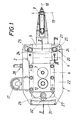
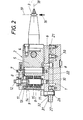
- the illustrated device for machining the base of threads consists essentially of a tool holder 1 which can be inserted into a tool holder of a lathe and a tool holder 2 for holding a roller tool 3.
- This tool holder is divided into two parts and points a support body 5 pivotably mounted about an axis 4 and a housing 6 accommodating the support body 5 with the axis 4.
- This housing 6 carries two eccentrically arranged, diametrically opposite and adjustable by means of an actuating shaft 7 stops 8 for the support body 5, which is pressed with the help of two spring assemblies 9 either against one of the two stops 8 in a working position: the spring assemblies 9 are open a bolt 10 between two end plates 11 so that they can be axially loaded via the bolt 10.
- a set screw 12 is provided for this purpose, which engages in a nut thread of the bolt 10, which is axially displaceable but is secured against rotation by a pin 13 in a passage opening 14 in the support body 5 of the tool carrier.
- the support body 5 forms an annular abutment 15 for the two spring assemblies 9 in the area of the passage opening, so that when the bolt 10 is adjusted via the set screw 12, one of the two spring assemblies 9 is prestressed between a face plate 11 and the abutment 15, while the other Spring assembly 9 is relieved. As a result of this prestressing of one of the two spring assemblies 9, the supporting body 5 is pressed against one of the two stops 8. If the roller tool 3 is now turned against the workpiece, a reaction force 16 results on the roller tool 3, which causes the support body 5 to pivot about its axis 4 and to lift the support body 5 from the stop 8 which is currently in use.
- the pressing force of the roller tool 8 on the workpiece is thus determined by the prestressing of the spring assemblies 9, which advantageously allows preselection of the pressing force.
- the adjustment path of the bolt 10 can be used, which is connected to a dial gauge 17 via a connecting rod (not shown in more detail).
- roller tool 3 In addition to setting the pressing force of Rollentechnik- zeu there g 3 to the workpiece alignment of the roller tool 3 with respect to the thread pitch is necessary to ensure a rolling of the rolling tool 3 on the basic profile along the thread grooves.
- the roller tool 3 must be able to be rotated about an axis running perpendicular to the axis of rotation 18 of the roller tool 3 and perpendicular to the work spindle axis of the lathe.
- the axis of rotation must lie in the main plane 19 of the roller tool 3, since only such a geometric axis of rotation permits inclination adjustment of the roller tool 3 without displacement from the adjustment area, since, however, no physical axis is provided in this area a circular arc guide 20 is provided for the tool carrier 2, the center of which lies on the axis of rotation 18 of the roller tool and in the main plane 19 normal to the axis. This ensures that the roller tool 3 can be pivoted to adapt to different thread pitches without additional displacement of the roller tool.
- the device shown can therefore be used regardless of the structure of the selected lathe, and also in cooperation with numerically controlled lathes.
- the circular arc guide 20 is designed as a circular arc-shaped groove 21 in a base plate 22 of the tool holder 1.
- Sleeve-shaped guide bodies 23 inserted into the housing 6 engage in this groove 21, as shown in FIG. 3.
- These guide bodies 23 are penetrated by clamping screws 24 which are mounted in the housing 6 of the tool carrier 2 and protrude through elongated holes 25 in the region of the groove base, so that the housing 6 can be clamped relative to the base plate 22 via the clamping screws 24.
- This clamp connection causes the circular arc guide 20 to remain free of loading forces of the roller tool and these loading forces are transferred from the tool holder 2 to the tool holder 1 via the clamping connection.
- Liche clamping screw 26 is provided which passes through an elongated hole 27 in the base plate 22 of the tool holder 1 with play, so that the pivoting adjustment of the tool carrier 2 is not hindered despite the straight elongated hole course.
- the device can accordingly be adapted to a desired thread pitch by actuating the screw drive 28, the inclined position of the roller tool 3 being able to be read using a scale 31 arranged on the base plate 22, which scale can be read with a pointer 32 cooperates on the housing 6. Since the scale 31 and the pointer 32 lie in the region of the end of the tool carrier 2 opposite the roller tool 3, a high reading accuracy is guaranteed even for small angles.
- the clamping screws 24 and 26 are tightened again, after which the thread can be machined after a corresponding selection of the pretensioning force for the spring assemblies 9 and the selection of the pressing direction. Due to the given setting options, machining of external and internal threads as well as right and left-hand threads can be carried out.
Landscapes
- Engineering & Computer Science (AREA)
- Mechanical Engineering (AREA)
- Electrical Discharge Machining, Electrochemical Machining, And Combined Machining (AREA)
- Transmission Devices (AREA)
- Nonmetallic Welding Materials (AREA)
- Machine Tool Units (AREA)
Applications Claiming Priority (2)
| Application Number | Priority Date | Filing Date | Title |
|---|---|---|---|
| AT3964/82 | 1982-10-29 | ||
| AT0396482A AT375285B (de) | 1982-10-29 | 1982-10-29 | Vorrichtung zum bearbeiten des profilgrundes von gewinden |
Publications (1)
| Publication Number | Publication Date |
|---|---|
| EP0109378A1 true EP0109378A1 (fr) | 1984-05-23 |
Family
ID=3557815
Family Applications (1)
| Application Number | Title | Priority Date | Filing Date |
|---|---|---|---|
| EP83890132A Withdrawn EP0109378A1 (fr) | 1982-10-29 | 1983-08-17 | Dispositif pour usiner le fond de profil des filetages |
Country Status (4)
| Country | Link |
|---|---|
| EP (1) | EP0109378A1 (fr) |
| JP (1) | JPS5993225A (fr) |
| AT (1) | AT375285B (fr) |
| NO (1) | NO833372L (fr) |
Cited By (2)
| Publication number | Priority date | Publication date | Assignee | Title |
|---|---|---|---|---|
| CN101972873A (zh) * | 2010-11-12 | 2011-02-16 | 吴江市菀坪镙丝厂 | 螺丝加工装置 |
| CN113084057A (zh) * | 2021-05-11 | 2021-07-09 | 成都中电锦江信息产业有限公司 | 一种用于管道套丝机上的能实现滚压螺纹加工的滚压装置 |
Citations (2)
| Publication number | Priority date | Publication date | Assignee | Title |
|---|---|---|---|---|
| DE110981C (fr) * | ||||
| US3800580A (en) * | 1973-01-08 | 1974-04-02 | Armco Steel Corp | Thread rolling apparatus |
Family Cites Families (1)
| Publication number | Priority date | Publication date | Assignee | Title |
|---|---|---|---|---|
| US4229966A (en) * | 1979-03-22 | 1980-10-28 | Jackson Warren M | Adjustable holder for the stationary die of a thread rolling machine |
-
1982
- 1982-10-29 AT AT0396482A patent/AT375285B/de not_active IP Right Cessation
-
1983
- 1983-08-17 EP EP83890132A patent/EP0109378A1/fr not_active Withdrawn
- 1983-09-19 NO NO833372A patent/NO833372L/no unknown
- 1983-10-25 JP JP58198417A patent/JPS5993225A/ja active Pending
Patent Citations (2)
| Publication number | Priority date | Publication date | Assignee | Title |
|---|---|---|---|---|
| DE110981C (fr) * | ||||
| US3800580A (en) * | 1973-01-08 | 1974-04-02 | Armco Steel Corp | Thread rolling apparatus |
Non-Patent Citations (1)
| Title |
|---|
| MASCHINENMARKT INDUSTRIEJOURNAL, Band 77, Nr. 12, 1971, Seiten 239-240, Würzburg, DE * |
Cited By (3)
| Publication number | Priority date | Publication date | Assignee | Title |
|---|---|---|---|---|
| CN101972873A (zh) * | 2010-11-12 | 2011-02-16 | 吴江市菀坪镙丝厂 | 螺丝加工装置 |
| CN101972873B (zh) * | 2010-11-12 | 2012-07-04 | 吴江市菀坪镙丝厂 | 螺丝加工装置 |
| CN113084057A (zh) * | 2021-05-11 | 2021-07-09 | 成都中电锦江信息产业有限公司 | 一种用于管道套丝机上的能实现滚压螺纹加工的滚压装置 |
Also Published As
| Publication number | Publication date |
|---|---|
| NO833372L (no) | 1984-04-30 |
| JPS5993225A (ja) | 1984-05-29 |
| AT375285B (de) | 1984-07-25 |
| ATA396482A (de) | 1983-12-15 |
Similar Documents
| Publication | Publication Date | Title |
|---|---|---|
| DE4008224C2 (fr) | ||
| DE2339873C2 (de) | Anordnung zum Einstellen und Befestigen eines ein Schneidplättchen tragenden Blocks in einer nutförmigen Aufnahme im Werkzeugkörper eines spanabhebenden Werkzeugs | |
| EP0126432A1 (fr) | Outil de fraisage | |
| DE2060869C3 (de) | Bohrkopf | |
| DE102022121719A1 (de) | Zentrierschraubstock | |
| DE2848229B1 (de) | Maschinenschraubstock | |
| DE1552252C3 (de) | Bohrkopf mit einstellbaren Werkzeugen | |
| DE3232689C2 (de) | Vorrichtung zum Schleifen von gerad- und wendelgenuteten Schneidwerkzeugen | |
| DE3635228C2 (fr) | ||
| DE3026513A1 (de) | Aufbohrwerkzeug, insbes. plansenker | |
| DE2614107A1 (de) | Fuehrungsbuechse fuer werkzeuge | |
| DE7438172U (de) | Ausdrehwerkzeug für die Feinstbearbeitung | |
| DE3925586C1 (en) | Endless belt grinding machine - prepares tensile test-pieces using flat table with rollers at either end | |
| DE1477274C3 (fr) | ||
| AT165330B (de) | Vorrichtung zur Bearbeitung von Werkstücken auf Werkzeugmaschinen, insbesondere für die Massenfertigung | |
| DE2920519C2 (fr) | ||
| DE19757567C2 (de) | Einrichtung zur Verstellung des Meßtisches an einem Meßmikroskop | |
| DE2936133A1 (de) | Dreipunkt-tischmessgeraet zum messen von kreisformfehlern | |
| DE2144203C3 (de) | Kurvengesteuerter Arbeitsschlitten für Werkzeugmaschinen | |
| DE2854466C2 (de) | Zeichenkopf für Zeichenmaschinen | |
| DE1552460C3 (de) | Drehmaschine mit einer von einem verschiebbaren Werkzeugschlitten getragenen Kopiervorrichtung | |
| DE9017411U1 (de) | Einrichtung zum Positionieren eines Werkzeuges | |
| DE3509161A1 (de) | Aufnahmedorn insbesondere fuer rundlaufende werkzeuge, beispielsweise messerkoepfe | |
| DE2417826A1 (de) | Elektromagnetische spannfutter-einrichtung | |
| DE2016148A1 (de) | Bohrstange fur Horizontalbohrwerke |
Legal Events
| Date | Code | Title | Description |
|---|---|---|---|
| PUAI | Public reference made under article 153(3) epc to a published international application that has entered the european phase |
Free format text: ORIGINAL CODE: 0009012 |
|
| AK | Designated contracting states |
Designated state(s): BE DE FR GB IT NL SE |
|
| 17P | Request for examination filed |
Effective date: 19840823 |
|
| STAA | Information on the status of an ep patent application or granted ep patent |
Free format text: STATUS: THE APPLICATION IS DEEMED TO BE WITHDRAWN |
|
| 18D | Application deemed to be withdrawn |
Effective date: 19851224 |
|
| RIN1 | Information on inventor provided before grant (corrected) |
Inventor name: SIEGWART, RUDOLF, ING. |