EP0109536B1 - Vorrichtung zur Absorptionsanalyse - Google Patents
Vorrichtung zur Absorptionsanalyse Download PDFInfo
- Publication number
- EP0109536B1 EP0109536B1 EP83110224A EP83110224A EP0109536B1 EP 0109536 B1 EP0109536 B1 EP 0109536B1 EP 83110224 A EP83110224 A EP 83110224A EP 83110224 A EP83110224 A EP 83110224A EP 0109536 B1 EP0109536 B1 EP 0109536B1
- Authority
- EP
- European Patent Office
- Prior art keywords
- optical fibers
- transmitted
- reaction
- reflecting mirror
- guiding optical
- Prior art date
- Legal status (The legal status is an assumption and is not a legal conclusion. Google has not performed a legal analysis and makes no representation as to the accuracy of the status listed.)
- Expired
Links
- 239000013307 optical fiber Substances 0.000 claims description 67
- 238000006243 chemical reaction Methods 0.000 claims description 49
- 239000012295 chemical reaction liquid Substances 0.000 claims description 38
- 238000005286 illumination Methods 0.000 claims description 16
- 229910052724 xenon Inorganic materials 0.000 claims description 7
- FHNFHKCVQCLJFQ-UHFFFAOYSA-N xenon atom Chemical compound [Xe] FHNFHKCVQCLJFQ-UHFFFAOYSA-N 0.000 claims description 7
- 230000003287 optical effect Effects 0.000 claims description 6
- QSHDDOUJBYECFT-UHFFFAOYSA-N mercury Chemical compound [Hg] QSHDDOUJBYECFT-UHFFFAOYSA-N 0.000 claims description 2
- 229910052753 mercury Inorganic materials 0.000 claims description 2
- 238000002835 absorbance Methods 0.000 description 27
- 238000005259 measurement Methods 0.000 description 11
- 239000003153 chemical reaction reagent Substances 0.000 description 9
- 210000002966 serum Anatomy 0.000 description 7
- 238000000354 decomposition reaction Methods 0.000 description 5
- 238000001514 detection method Methods 0.000 description 5
- 230000000694 effects Effects 0.000 description 5
- 229910052736 halogen Inorganic materials 0.000 description 5
- 150000002367 halogens Chemical class 0.000 description 5
- 238000011481 absorbance measurement Methods 0.000 description 4
- 230000002411 adverse Effects 0.000 description 2
- 239000000203 mixture Substances 0.000 description 2
- 206010067484 Adverse reaction Diseases 0.000 description 1
- 102000004190 Enzymes Human genes 0.000 description 1
- 108090000790 Enzymes Proteins 0.000 description 1
- 206010023126 Jaundice Diseases 0.000 description 1
- 230000006838 adverse reaction Effects 0.000 description 1
- 238000010276 construction Methods 0.000 description 1
- 238000012937 correction Methods 0.000 description 1
- 238000002474 experimental method Methods 0.000 description 1
- 238000000034 method Methods 0.000 description 1
- 238000012986 modification Methods 0.000 description 1
- 230000004048 modification Effects 0.000 description 1
- PIRWNASAJNPKHT-SHZATDIYSA-N pamp Chemical compound C([C@@H](C(=O)N[C@@H](CCCNC(N)=N)C(=O)N[C@@H](CCCCN)C(=O)N[C@@H](CCCCN)C(=O)N[C@@H](CC=1C2=CC=CC=C2NC=1)C(=O)N[C@@H](CC(N)=O)C(=O)N[C@@H](CCCCN)C(=O)N[C@@H](CC=1C2=CC=CC=C2NC=1)C(=O)N[C@@H](C)C(=O)N[C@@H](CC(C)C)C(=O)N[C@@H](CO)C(=O)N[C@@H](CCCNC(N)=N)C(N)=O)NC(=O)[C@H](CCC(O)=O)NC(=O)[C@H](CO)NC(=O)[C@H](C)NC(=O)[C@@H](NC(=O)[C@H](CC(O)=O)NC(=O)[C@H](CC(C)C)NC(=O)[C@H](CCCNC(N)=N)NC(=O)[C@H](C)N)C(C)C)C1=CC=CC=C1 PIRWNASAJNPKHT-SHZATDIYSA-N 0.000 description 1
- 238000012545 processing Methods 0.000 description 1
- 230000001105 regulatory effect Effects 0.000 description 1
- 239000000126 substance Substances 0.000 description 1
- XLYOFNOQVPJJNP-UHFFFAOYSA-N water Substances O XLYOFNOQVPJJNP-UHFFFAOYSA-N 0.000 description 1
Images

Classifications
-
- G—PHYSICS
- G01—MEASURING; TESTING
- G01N—INVESTIGATING OR ANALYSING MATERIALS BY DETERMINING THEIR CHEMICAL OR PHYSICAL PROPERTIES
- G01N21/00—Investigating or analysing materials by the use of optical means, i.e. using sub-millimetre waves, infrared, visible or ultraviolet light
- G01N21/17—Systems in which incident light is modified in accordance with the properties of the material investigated
- G01N21/25—Colour; Spectral properties, i.e. comparison of effect of material on the light at two or more different wavelengths or wavelength bands
- G01N21/251—Colorimeters; Construction thereof
- G01N21/253—Colorimeters; Construction thereof for batch operation, i.e. multisample apparatus
-
- G—PHYSICS
- G01—MEASURING; TESTING
- G01J—MEASUREMENT OF INTENSITY, VELOCITY, SPECTRAL CONTENT, POLARISATION, PHASE OR PULSE CHARACTERISTICS OF INFRARED, VISIBLE OR ULTRAVIOLET LIGHT; COLORIMETRY; RADIATION PYROMETRY
- G01J3/00—Spectrometry; Spectrophotometry; Monochromators; Measuring colours
- G01J3/28—Investigating the spectrum
- G01J3/2803—Investigating the spectrum using photoelectric array detector
-
- G—PHYSICS
- G01—MEASURING; TESTING
- G01N—INVESTIGATING OR ANALYSING MATERIALS BY DETERMINING THEIR CHEMICAL OR PHYSICAL PROPERTIES
- G01N2201/00—Features of devices classified in G01N21/00
- G01N2201/08—Optical fibres; light guides
-
- Y—GENERAL TAGGING OF NEW TECHNOLOGICAL DEVELOPMENTS; GENERAL TAGGING OF CROSS-SECTIONAL TECHNOLOGIES SPANNING OVER SEVERAL SECTIONS OF THE IPC; TECHNICAL SUBJECTS COVERED BY FORMER USPC CROSS-REFERENCE ART COLLECTIONS [XRACs] AND DIGESTS
- Y10—TECHNICAL SUBJECTS COVERED BY FORMER USPC
- Y10T—TECHNICAL SUBJECTS COVERED BY FORMER US CLASSIFICATION
- Y10T436/00—Chemistry: analytical and immunological testing
- Y10T436/11—Automated chemical analysis
- Y10T436/113332—Automated chemical analysis with conveyance of sample along a test line in a container or rack
Definitions
- This invention relates to an apparatus for absorptiometric analysis in the field of automatic chemical analysis apparatus and, more particularly, to an absorbance measuring apparatus which can quickly effect absorbance measurement processes on a number of samples for a plurality of measurement items.
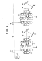
- Figure 1 shows a conventional absorbance measuring apparatus. Beam emitted from a light source 10 is incident on a bundle of optical fibers 12 and is led through these optical fibers 12 to reaction tubes 20 for a plurality of channels located in, for instance, three measuring stations, i.e., first to third measuring stations 14, 16 and 18. In the illustrated example, each measuring station has four channels, though a reaction tube for only one of these channels is shown for each measuring station. Reflecting mirrors 22 are each disposed on the side of each reaction tube 20 opposite the beam emission end of the corresponding optical fiber. Beam emitted from each optical fiber 12 is transmitted through a reaction liquid contained in each reaction tube 20 and is then reflected by each reflecting mirror 22.
- Beams reflected from the individual reflecting mirrors 22 are incident on two-wavelength spectrometers 24, 26 and 28, respectively.
- Each of the two-wavelength spectrometers includes a beam splitter 30 and spectrometers 32 and 34.
- the beam splitter30 splits the incident beam into two light beams which are led to the pair of spectrometers 32, 34.
- the spectrometers 32, 34 each include a filter and a photo-detector, and can measure the intensity of transmitted light of particular wavelengths.
- a sample serum for example, is distributed to the reaction tubes 20 for four channels, and different reagents for the respective channels are poured into the sample serum in the individual reaction tubes 20.
- the reaction tubes 20, each of which contains the reaction liquid, i.e., the mixture of sample serum and reagent, are brought to the successive first to third measuring stations 14, 16 and 18, and the intensity of transmitted beam is measured for two different wavelengths at each of the measuring stations. Changes in the absorbance (i.e., the reaction degree) of the reaction liquid, over time, can thus be measured, whereby an examination can be conducted for four different channels of items (such as GOT and GPT) in the respective samples.
- items such as GOT and GPT
- the optical fibers 12 have a low filling factor, so that a high output halogen lamp which continuously emits light is used as the light source 10. Beam of such high energy level, however, would cause decomposition of a reaction liquid obtained from, for instance, the serum of a jaundice patient, thus disabling accurate examination.
- Figure 2 shows a different conventional absorbance measuring apparatus.
- a plurality of reaction cuvettes 46 are disposed along a circle for each of the different channels 36, 38,....
- the reaction cuvettes 46 for each channel are moved about the center of the circle.
- beam emitted from a light source 48 is converged by a condenser lens 50 and transmitted through the reaction liquid in the reaction cuvette 46.
- Transmitted beam is passed through a slit 52 to be incident on a diffracting grating 54.
- Diffracted monochromatic light beams from the diffracting grating 54 are detected in a photodiode array 56.
- a particular item of examination is done, that is, the same reagent is poured into the reaction cuvettes 46 in the same channel.
- a sample e.g., a serum
- a sample is distributed through a tube 42 and pipette 44 into the reaction cuvettes 46 in the same channels 36, 38, ....
- it is mixed with a reagent so that a reaction liquid is produced.
- Changes in the absorbance of the reaction liquid with time are measured by each diffracting grating 54 and photodiode array 56.
- the absorbance is measured by the same spectrometer (i.e., by diffracting grating 54 and photodiode array 56) for each particular item, and the measurement is thus free from errors due to fluctuations of the spectrometer's detection characteristics.
- the light source 48 must be provided for each channel. Therefore, the operation and service are rather cumbersome. In addition, high power must be consumed for driving the light sources. Further, the size of the apparatus is inevitably large.
- measuring stations are provided for the respective wavelengths of the absorbance measurement, so that an enlarged apparatus is again inevitable.
- the precision of detection is influenced by the balance of the filter.
- One object of the present invention is to provide an apparatus for absorptiometric analysis, with which the measurement of absorbance for a plurality of channels can be done by a single spectro-photometric means, so that it is possible to obtain high precision of absorbance measurement and highly reliable examination results.
- Another object of the present invention is to provide an apparatus for absorptiometric analysis, which can use a single and common light source in the absorbance measurement of a plurality of channels, so that it is possible to reduce the size of the device.
- a further object of this invention is to provide an apparatus for absorptiometric analysis, which is free from decomposition or like adverse reactions of the reaction liquid which is the subject of measurement.
- an apparatus for measuring the absorbance of reaction liquids contained in reaction vessels, at n measuring points in each of n channels, comprising:
- the measurement of the absorbance of reaction liquids for a plurality of channels at a plurality of measuring stations is done by the common diffraction grating the photo-detector array.
- the measurement is free from errors due to fluctuations of the light-electricity conversion characteristics among different spectrometers, and complicated error correction with respect to the different spectrometers is unnecessary.
- the size and cost of the apparatus can be reduced.
- beam emitted from single illuminating means i.e., from a single light source
- the apparatus can be operated and serviced more easily and can consume less power compared to the conventional structure using a plurality of light sources.
- the apparatus can be further reduced in size. Furthermore, since transmitted beams from the reaction liquids for a plurality of channels and at a plurality of measuring stations are selectively led to the slit members with the rotation of the first reflecting mirror, the switching of transmitted beams to be detected by the diffraction grating and photo-diode array can be done at a high speed, so that the processing speed can be increased.
- the illuminating means if a light source driven for light emission by a pulse drive system, e.g., a xenon flash lamp, is used as the illuminating means, the light energy supplied per unit of time may be low, though the brightness is high, so that it is possible to avoid adverse effects of illumination on the reaction liquid. Further, with the high brightness of the illumination light, the intensity of transmitted beam can be detected with a high degree of precision, even if the filling factor of the optical fibers is so low that light loss therein is high.
- a pulse drive system e.g., a xenon flash lamp
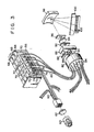
- FIGS 3 and 4 show an embodiment of the apparatus for measuring absorbance according to the present invention.
- a light source 60 as shown in a xenon flashed pamp. It is driven by a pulse drive system and emits high brightness beam as light pulses, for instance with a pulse duration of 3 psec and at a frequency of 100 Hz. Further, it intermittently emits beam, for instance 12 times in every 6 seconds, as will be described later in detail. Beam emitted from the light source 60 is converged by a condenser lens 62 into a parallel beam, which is incident on the beam receiving end of a bundle of optical fibers 64 for guiding illumination beam (which are 12 in number in the illustrated example).
- a plurality of cassettes 68 (only three thereof being shown), each supporting four reaction cuvettes 70 arranged in a row, are arranged in an endless line perpendicular to the row of reaction cuvettes 70 in each cassette 68.
- the reaction cuvettes 70 supported by the individual cassettes 68 have their lower half immersed in a constant- temperature medium, e.g., warm water, contained in a thermostatic bath 66.
- the constant- temperature medium is held at a predetermined reaction temperature.
- the cassettes 68 are fed intermittently along the endless line with supported reaction cuvettes 70 partly immersed in the medium. For instance, they are intermittently moved to a position having been occupied by the preceding cassette after they have been held stationary for 6 seconds.
- each measuring station Three measuring stations, for instance, are provided on the endless line at suitable positions thereon, at which positions the cassettes 68 are held stationary for the period noted above.
- four pairs of beam path defining members 74 and 76 e.g., reflecting mirrors or prisms, are provided.
- the beam path defining members 74 and 76 in each pair are disposed on the opposite sides of each reaction cuvettes 70 in the longitudinal direction of the cassette 68.
- a condenser lens 72 having a vertical lens axis is disposed right beneath each beam path defining member 74.
- the emission end of each of the optical fibers 64 for guiding illumination beam is disposed right beneath each condenser lens 72 such that its optical axis coincides with the lens axis of the condenser lens 72.
- a condenser lens 78 having a vertical lens axis is disposed right beneath each beam path defining member 76.
- the beam receiving end of each of optical fibers 80 for guiding transmitted beam is disposed right beneath each condenser lens 78 such that its optical axis coincides with the lens axis of the condenser lens 78.
- the beam emitted from each optical fiber 64 is condensed by each condenser lens 72, and its path is then changed by each beam path defining member 74 to a horizontal path.
- the horizontal beam is transmitted through the reaction liquid in each reaction cuvettes 70.
- the path of the transmitted beam is diverted by each beam path defining member 76 toward each condenser lens 78, so that the beam is condensed in such a way as to be incident on each optical fiber 80.
- every four optical fibers are led to each of the three measuring stations.
- the four optical fibers 64 are led to their respective reaction cuvettes 70.
- the optical fibers 80 for guiding transmitted beam led out from the reaction cuvettes 70 at the measuring positions constitute a bundle of optical fibers. They are 12 in number, and four of them are led out from the respective reaction cuvettes 70 in each measuring station.
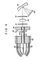
- the beam emission ends of the 12 optical fibers 80 are supported by a support member 82 at positions thereof which fall on a circle.
- the support member 82 is secured to the frame of the apparatus.
- a shaft 84 rotatably penetrates the center of the support member 82 and extends substantially at right angles to the plane of the support member 82.
- the beam emission ends of the 12 optical fibers 80 are uniformly spaced on the support member 82 along a circle with the center thereof concentric with the axis of the shaft 84. They are secured to the support member 82 such that they extend parallel to the axis of the shaft 84.
- the beam receiving end and beam emission end of the optical fibers 64 and the beam receiving end of the optical fibers 80 are all circular in sectional shape.
- the beam emission end of the optical fibers 80 is elongated in sectional shape like a slit.
- the beam emission ends of the individual optical fibers 80 are secured to the support member 82, in such a way that they extend in the same direction.
- the shaft 84 projects from the side of the support member 82, opposite the side on which the beam emission ends of the optical fibers 80 are secured.
- a rotor 86 is secured to the free end of the projecting portion of the shaft 84. It carries a reflecting mirror 88 mounted on its side facing the support member 82 and at a position which is adapted to be brought into alignment with the beam emission end of each optical fiber 80.
- the shaft 84 carries a reflecting mirror 90 facing the reflecting mirror 88.
- the shaft 84 also has a notch formed in its portion on the side of the reflecting mirror 90 nearer the rotor 86 and also sectionally on the side nearer the reflecting mirror 88.
- the rotor 86 has a see-through hole 86a corresponding in position to the notch of the shaft 84. Beam emitted from the beam emission end of the optical fiber 80 aligned to the reflecting mirror proceeds along a path as shown by a dot-and-bar line. More particularly, it first proceeds along a path parallel to the axis of the shaft-84 and is reflected by the reflecting mirror 88 to be incident on the reflecting mirror 90. Beam reflected by the reflecting mirror 90 proceeds along a path substantially coincided with the axis of the shaft 84, through the see-through hole 86a of the rotor 86.
- a pair of slit members 92, 96 is disposed on the path of beam from the rotor 86 (i.e., on the axis of the shaft 84).
- a condenser lens 94 is further disposed on the beam path noted above between the slit members 92 and 96.
- the slit members 92 and 96 have respective slits extending in the direction of the elongated beam emission ends of the optical fibers 80, the section of the emission ends having a shape corresponding to the slits of the slit members 92 and 96.
- Beam having passed through the slit member 96 is incident on and is diffracted by a diffraction grating 98.
- Diffracted beam is incident on a photodiode array 100 consisting of a plurality of photodiodes 102 arranged in a row.
- the intensity of beam for each particular wavelength is detected by each photodiode 102.
- the photodiodes 102 convert the incident beam into electric signals, which are transferred to a calculating unit (not shown).
- the calculating unit calculates the absorbance of the reaction liquid according to the results of detection of the intensity of transmitted beam provided from the photo-diode array 100.
- a sample e.g., a serum of a patient
- Predetermined reagents for different examination items i.e., GOT, GPT, a-GPT and amilase are charged into the respective reaction cuvettes 70.
- the individual cassettes 68 with the reaction cuvettes 70 containing respective reaction liquids i.e., mixtures of sample and reagent
- the light source 60 which is a xenon flashed lamp, is driven to emit beam intermittently, 12 times.
- the beam emission is caused by a pulse drive system with a flashing period of approximately 3 usecond and a flashing frequency of 100 Hz.
- One beam emission period is 0.2 second.
- optical fibers of a low filling factor may be used as the optical fibers 64 and 80 to obtain the measurement of absorbance without being adversely influenced by the loss of light because of the high brightness of beam.
- the inventor conducted experiments about the decomposition of bilirbin by illumination of flashlight from the xenon flashed lamp, and it was confirmed that the decomposition that results is very little compared to the case of continuous illumination using the halogen lamp.
- the same effects may be obtained by using a mercury flashed lamp, a pulse laser, etc., in lieu of the xenon flashed lamp serving as the light source 60. Further, the same effects may be obtained by using an illuminating means which provides beam from a halogen lamp, as non-continuous beam; by means of chopping, instead of the pulse drive system light source.
- Beam emitted from the light source 60 is coupled, through the condenser lens 62, to the beam receiving ends of the optical fibers 64. Through these optical fibers 64, the beam is led to the reaction cuvettes 70 in the first to third measuring stations. More specifically, beam emitted from the beam emission end of each optical fibers 64 is coupled through the associated condenser lens 72 and beam path defining member 74 and transmitted through the reaction liquid in the reaction cuvette 70. Transmitted beam is coupled through the associated beam path defining member 76 and condenser lens 78 to be incident on the beam receiving end of the corresponding optical fiber 80. Beam coupled to the optical fibers 80 is emitted from the beam emission ends thereof supported by the support member 82. During each stationary period of the cassettes 68, transmitted beam is emitted 12 times from the beam emission ends of the 12 optical fibers 80.
- the rotor 86 While transmitted beam is being emitted from the bundle of optical fibers 80 for the first period, the rotor 86 is held at a position at which the beam emission end of the first optical fiber 80 in the bundle is aligned to the reflecting mirror 88. When the emission of transmitted beam for the first period is over, the rotor 86 is rotated to a next stationary position, at which the beam emission end of the second optical fiber 80 adjacent to the first optical fiber is aligned to the reflecting mirror 88. The rotor 86 is held stationary at this position during the emission of the transmitted beam for the second period. When the second period of transmitted beam emission is over, the rotor 86 is moved again and is brought to a position, at which the third optical fiber 80 adjacent to the second is aligned to the reflecting mirror 88.
- This sequence of operation of the rotor 86 is caused 12 times successively while the cassettes 68 are held stationary. While the rotor 86 is intermittently rotated to complete one rotation, beams transmitted through the reaction liquids in the 12 reaction vessels at the first to third measuring stations are successively caused to pass through the slit member 92, condenser lens 94 and slit member 96. It is to be understood that the rotor 86 serves as beam switch means for independently and successively supplying beam transmitted through the reaction liquids in the individual reaction cuvettes 70 through the slit member 92, condenser lens 94 and slit member 96. Since the path of the transmitted beam is regulated by the pair of reflecting mirrors 88, 90, the transmitted beam emitted from each optical fiber 80 can be supplied to the slit member 92 without substantial loss.
- the transmitted beam having been passed through slit member 92, the condenser lens 94 and slit member 96, is incident on the diffraction grating 98.
- Diffracted beam from the diffraction grating 98 is detected by the photo-detectors 102 of the photo-detector array 100 for individual predetermined wavelengths.
- the slit members 92, 96 are provided for increasing the directivity of the transmitted beam. While with a single slit, the directivity of transmitted light is not significantly increased, it can be substantially increased by providing a pair of slits.
- the beam emission end of the optical fibers 80 has an elongate shape corresponding to the shape of the slit of the slit members 92 and 96.
- a beam having an elongate sectional shape is emitted from the beam emission end of each optical fiber 80.
- the proportion of the transmitted beam blocked by the slit member 92 is very low compared to the case where an ordinary beam having a circular sectional profile is blocked by the slit member 92. This means that the light energy of the transmitted beam emitted from the beam emission end having the elongate shape similar to the shape of the slit is blocked only slightly by the slit members 92 and 96, so that it can be effectively supplied to the photo-detectors 102.
- Data on the intensity of transmitted beam detected by the photo-detectors 102 is stored in a memory of the calculating unit. While the cassettes 68 are held stationary, the intensity of transmitted beam from the reaction liquids in the 12 reaction cuvettes 70 is obtained for the individual predetermined frequencies. This data are stored in the memory. They are obtained and stored every time the cassettes 68 are moved to the next position.
- the calculating unit reads out data on the intensity of transmitted beam which data is obtained with respect to a particular reaction liquid for the first to third measuring stations and is selected from among data stored in the memory, thereby calculating the absorbance.
- the absorbance is usually obtained on the basis of commonly termed two-wavelength measurement, to eliminate background noise. More specifically, the difference between the absorbances with respect to two wavelengths, i.e., a main wavelength and an auxiliary wavelength, is obtained from the data obtained at each measuring station. This difference in the absorbance is multiplied by a preliminarily obtained constant for conversion to the absorbance with respect to the main wavelength.
- the wavelength accuracy is high, since the transmitted beam is incident on the diffraction grating 98 after it has been passed through the pair slit members 92 and 96.
- the two-wavelength measurement can be obtained with a high degree of accuracy, without a deviation in the pattern relating to the wavelength, or absorbance with respect to the wavelength.
- the absorbance obtained for each reaction liquid, in the above-described manner, is plotted against time, until the reaction cuvette is brought to the first to third measuring stations, after addition of the reagent to the sample. Changes in the absorbance, i.e., the reaction degree, with time thus can be obtained. Whether the pertinent patient is normal or not with respect to the given reagent item is judged from the changes in the reaction degree with time.
- the number of channels and number of measuring stations are not limited to 4 and 3, respectively, as in the above embodiment, but may be suitably set, according to the examination items and other factors.
- three or more slit members may be provided, instead of a pair of slit members, between the rotor 86 and diffraction grating 98.
- the beam switch means comprising the support member 82, shaft 84, rotor 86 and reflecting mirrors 88, 90, between the condenser lens 62 and the bundle of optical fibers 64.
- beam from the light source 60 is successively distributed to the 12 optical fibers, with the rotation of the rotor 86.
- no beam is supplied to the reaction liquid, with respect to which the measurement of absorbance is not made. thus, the influence of the transmitted beam on the reaction liquid can be further reduced.
Landscapes
- Physics & Mathematics (AREA)
- Spectroscopy & Molecular Physics (AREA)
- Health & Medical Sciences (AREA)
- Life Sciences & Earth Sciences (AREA)
- Chemical & Material Sciences (AREA)
- Analytical Chemistry (AREA)
- Biochemistry (AREA)
- General Health & Medical Sciences (AREA)
- General Physics & Mathematics (AREA)
- Immunology (AREA)
- Pathology (AREA)
- Investigating Or Analysing Materials By Optical Means (AREA)
- Spectrometry And Color Measurement (AREA)
Claims (7)
Applications Claiming Priority (2)
| Application Number | Priority Date | Filing Date | Title |
|---|---|---|---|
| JP179753/82 | 1982-10-15 | ||
| JP57179753A JPS5970946A (ja) | 1982-10-15 | 1982-10-15 | 吸光度測定装置 |
Publications (2)
| Publication Number | Publication Date |
|---|---|
| EP0109536A1 EP0109536A1 (de) | 1984-05-30 |
| EP0109536B1 true EP0109536B1 (de) | 1987-02-25 |
Family
ID=16071271
Family Applications (1)
| Application Number | Title | Priority Date | Filing Date |
|---|---|---|---|
| EP83110224A Expired EP0109536B1 (de) | 1982-10-15 | 1983-10-13 | Vorrichtung zur Absorptionsanalyse |
Country Status (4)
| Country | Link |
|---|---|
| US (1) | US4685801A (de) |
| EP (1) | EP0109536B1 (de) |
| JP (1) | JPS5970946A (de) |
| DE (1) | DE3369888D1 (de) |
Cited By (3)
| Publication number | Priority date | Publication date | Assignee | Title |
|---|---|---|---|---|
| DE3840719A1 (de) * | 1987-12-02 | 1989-06-22 | Olympus Optical Co | Automatisches analysiergeraet |
| DE10222822A1 (de) * | 2002-05-21 | 2003-12-04 | Conducta Endress & Hauser | Online-Analysator |
| US10955292B2 (en) * | 2016-06-10 | 2021-03-23 | Bomill Ab | Detector system comprising a plurality of light guides and a spectrometer comprising the detector system |
Families Citing this family (53)
| Publication number | Priority date | Publication date | Assignee | Title |
|---|---|---|---|---|
| US5112134A (en) * | 1984-03-01 | 1992-05-12 | Molecular Devices Corporation | Single source multi-site photometric measurement system |
| JPS60253821A (ja) * | 1984-05-30 | 1985-12-14 | Toshiba Corp | 多波長分光器用光スイツチ光学系 |
| US4616134A (en) * | 1984-07-17 | 1986-10-07 | Chevron Research Company | High resolution geologic sample scanning apparatus and process of scanning geologic samples |
| US4664522A (en) * | 1984-08-24 | 1987-05-12 | Guided Wave, Inc. | Optical waveguide spectrum analyzer and method |
| FR2569864B1 (fr) * | 1984-09-04 | 1987-01-30 | Commissariat Energie Atomique | Equipement d'emission et de distribution de lumiere par fibres optiques, notamment pour le controle spectrophotometrique en ligne a l'aide d'un spectrophotometre double faisceau |
| JPS61281940A (ja) * | 1985-06-07 | 1986-12-12 | Shimadzu Corp | 分析用多波長測光装置 |
| ATE138475T1 (de) * | 1985-09-30 | 1996-06-15 | Molecular Devices Corp | Photometrisches vielortmesssystem mit einer quelle |
| DE3544512A1 (de) * | 1985-12-17 | 1987-06-19 | Bodenseewerk Perkin Elmer Co | Polychromator |
| US5040889A (en) * | 1986-05-30 | 1991-08-20 | Pacific Scientific Company | Spectrometer with combined visible and ultraviolet sample illumination |
| JPH051809Y2 (de) * | 1986-05-31 | 1993-01-18 | ||
| JPH0619079Y2 (ja) * | 1988-04-28 | 1994-05-18 | オリンパス光学工業株式会社 | 自動分析装置における分光装置 |
| US5184193A (en) * | 1989-01-04 | 1993-02-02 | Guided Wave | Dual fiber optic spectrophotometer |
| US5002392A (en) * | 1989-12-01 | 1991-03-26 | Akzo N.V. | Multichannel optical monitoring system |
| US5646046A (en) * | 1989-12-01 | 1997-07-08 | Akzo Nobel N.V. | Method and instrument for automatically performing analysis relating to thrombosis and hemostasis |
| FI86340C (fi) * | 1990-10-31 | 1992-08-10 | Labsystems Oy | Foerfarande foer ledning av ljus. |
| US5365334A (en) * | 1990-12-21 | 1994-11-15 | The United States Of America As Represented By The Secretary Of The Navy | Micro photoreflectance semiconductor wafer analyzer |
| US5210590A (en) * | 1992-02-18 | 1993-05-11 | L. T. Industries, Inc. | Rapid scanning spectrographic analyzer |
| US5245176A (en) * | 1992-06-10 | 1993-09-14 | Akzo N.V. | Method for scanning photodiodes utilizing a shutter mechanism having opening and closing transition times |
| CA2100020C (en) * | 1992-07-17 | 2001-09-11 | Walter Blumenfeld | Methods and apparatus for detecting bacterial growth by spectrophotometric sampling of a fiber-optic array |
| US6204919B1 (en) | 1993-07-22 | 2001-03-20 | Novachem Bv | Double beam spectrometer |
| US5432096A (en) * | 1993-12-20 | 1995-07-11 | Cetac Technologies Inc. | Simultaneous multiple, single wavelength electromagnetic wave energy absorbtion detection and quantifying spectrophotometric system, and method of use |
| JP3250426B2 (ja) * | 1995-09-27 | 2002-01-28 | 安藤電気株式会社 | 光スペクトラム測定装置 |
| AU728330B2 (en) * | 1996-02-21 | 2001-01-04 | Biomerieux Vitek, Inc. | Automatic sample testing |
| US5670375A (en) * | 1996-02-21 | 1997-09-23 | Biomerieux Vitek, Inc. | Sample card transport method for biological sample testing machine |
| DE19615957A1 (de) * | 1996-04-22 | 1997-10-23 | Hans Joachim Bruins | Verteilervorrichtung |
| US5853666A (en) * | 1997-02-12 | 1998-12-29 | Biomerieux Vitek, Inc. | Optical reader and sample card transport stations for biological sample testing machine |
| US6469311B1 (en) | 1997-07-16 | 2002-10-22 | Molecular Devices Corporation | Detection device for light transmitted from a sensed volume |
| US6071748A (en) * | 1997-07-16 | 2000-06-06 | Ljl Biosystems, Inc. | Light detection device |
| US6097025A (en) * | 1997-10-31 | 2000-08-01 | Ljl Biosystems, Inc. | Light detection device having an optical-path switching mechanism |
| WO2000050877A1 (en) | 1999-02-23 | 2000-08-31 | Ljl Biosystems, Inc. | Frequency-domain light detection device |
| US6297018B1 (en) | 1998-04-17 | 2001-10-02 | Ljl Biosystems, Inc. | Methods and apparatus for detecting nucleic acid polymorphisms |
| US6982431B2 (en) | 1998-08-31 | 2006-01-03 | Molecular Devices Corporation | Sample analysis systems |
| US6992761B2 (en) | 1997-09-20 | 2006-01-31 | Molecular Devices Corporation | Broad range light detection system |
| US6326605B1 (en) | 1998-02-20 | 2001-12-04 | Ljl Biosystems, Inc. | Broad range light detection system |
| US6576476B1 (en) | 1998-09-02 | 2003-06-10 | Ljl Biosystems, Inc. | Chemiluminescence detection method and device |
| US6825921B1 (en) | 1999-11-10 | 2004-11-30 | Molecular Devices Corporation | Multi-mode light detection system |
| EP0953838A1 (de) * | 1998-05-01 | 1999-11-03 | F. Hoffmann-La Roche Ag | Vorrichtung zur gleichzeitigen Überwachung von in einer Mehrzahl von Reaktionsgefässen stattfindenden Reaktionen |
| DE19824652A1 (de) * | 1998-05-25 | 2000-01-20 | Analyticon Ag Biotechnologie P | Vorrichtung zur Detektion von flüssigchromatographisch getrennten Substanzen mittels UV- oder Fluoreszenzspektren |
| AU5667599A (en) | 1998-07-27 | 2000-02-21 | Ljl Biosystems, Inc. | Apparatus and methods for time-resolved spectroscopic measurements |
| AU5223899A (en) * | 1998-07-27 | 2000-02-21 | Ljl Biosystems, Inc. | Apparatus and methods for spectroscopic measurements |
| US6468764B1 (en) * | 1999-01-20 | 2002-10-22 | Walden Lewis Gibbs | Automated staining and decolorization of biological material |
| US6307630B1 (en) * | 1999-11-19 | 2001-10-23 | Hach Company | Turbidimeter array system |
| GB2362460A (en) * | 2000-05-19 | 2001-11-21 | William Howard Considine | Spectroscope |
| US6534768B1 (en) | 2000-10-30 | 2003-03-18 | Euro-Oeltique, S.A. | Hemispherical detector |
| DE10216179A1 (de) * | 2002-04-04 | 2003-10-23 | Hartmut Lucht | Verfahren zur spektrometrischen Messung der Extinktion, der Transmission, der Remission oder der Reflexion von Proben und Spektrometer zur Durchführung des Verfahrens |
| US6894777B2 (en) * | 2002-08-07 | 2005-05-17 | Romaine R. Maiefski | Multiple-channel UV spectrometer assembly |
| CN103941027B (zh) | 2005-03-29 | 2016-09-07 | 希森美康株式会社 | 标本分析方法及标本分析装置 |
| JP4881855B2 (ja) * | 2005-03-29 | 2012-02-22 | シスメックス株式会社 | 検体分析方法および検体分析装置 |
| JP4875391B2 (ja) * | 2006-03-30 | 2012-02-15 | シスメックス株式会社 | 検体分析装置 |
| JP2008281392A (ja) * | 2007-05-09 | 2008-11-20 | Olympus Corp | 測光装置及び自動分析装置 |
| JP2011064676A (ja) | 2009-08-18 | 2011-03-31 | Horiba Ltd | 分析装置 |
| EP2893320B1 (de) * | 2012-08-20 | 2020-12-23 | Siemens Healthcare Diagnostics Inc. | Zweischaliges luminometer |
| WO2015026794A1 (en) | 2013-08-22 | 2015-02-26 | Becton, Dickinson And Company | Nephelometry method and apparatus for determining the concentration of suspended particles in an array of sample containers |
Family Cites Families (12)
| Publication number | Priority date | Publication date | Assignee | Title |
|---|---|---|---|---|
| US3697185A (en) * | 1970-08-06 | 1972-10-10 | Technicon Instr | Method and apparatus for the time sharing of multiple channel analysis means |
| GB1486210A (en) * | 1973-11-14 | 1977-09-21 | Suovaniemi Osmo Antero | Cuvette assembly for use in automatic reading and recording of reaction results |
| DE2408543A1 (de) * | 1974-02-22 | 1975-08-28 | Osmo Antero Suovaniemi | Analysator |
| JPS5247345B2 (de) * | 1974-12-26 | 1977-12-01 | ||
| JPS54151084A (en) * | 1978-05-19 | 1979-11-27 | Hitachi Ltd | Photometer |
| JPS567037A (en) * | 1979-06-29 | 1981-01-24 | Fumio Inaba | Remote substance density analyzing optical measuring apparatus |
| DE3031959A1 (de) * | 1979-08-28 | 1981-03-19 | Ishikawajima-Harima Heavy Industries Co., Ltd., Tokyo | Verfahren und anordnung zum messen der temperatur und des spektralen faktors von proben |
| JPS56168145A (en) * | 1980-05-29 | 1981-12-24 | Ishikawajima Harima Heavy Ind Co Ltd | Multichannel radiation flux measuring device |
| FR2469713A1 (fr) * | 1979-11-15 | 1981-05-22 | Lang Kurt | Methode pour la distribution, la preparation et la mesure de liquides, en particulier de serums de patients et de reactifs et appareil pour la mise en oeuvre de la methode |
| JPS56131448U (de) * | 1980-03-07 | 1981-10-06 | ||
| JPS5872108A (ja) * | 1981-10-24 | 1983-04-30 | Mitsubishi Electric Corp | 光回路装置 |
| US4487504A (en) * | 1982-09-01 | 1984-12-11 | Pacific Scientific Instruments Company | Reflectance measuring instrument with integrating sphere |
-
1982
- 1982-10-15 JP JP57179753A patent/JPS5970946A/ja active Pending
-
1983
- 1983-10-13 DE DE8383110224T patent/DE3369888D1/de not_active Expired
- 1983-10-13 EP EP83110224A patent/EP0109536B1/de not_active Expired
-
1985
- 1985-12-23 US US06/814,169 patent/US4685801A/en not_active Expired - Fee Related
Cited By (3)
| Publication number | Priority date | Publication date | Assignee | Title |
|---|---|---|---|---|
| DE3840719A1 (de) * | 1987-12-02 | 1989-06-22 | Olympus Optical Co | Automatisches analysiergeraet |
| DE10222822A1 (de) * | 2002-05-21 | 2003-12-04 | Conducta Endress & Hauser | Online-Analysator |
| US10955292B2 (en) * | 2016-06-10 | 2021-03-23 | Bomill Ab | Detector system comprising a plurality of light guides and a spectrometer comprising the detector system |
Also Published As
| Publication number | Publication date |
|---|---|
| DE3369888D1 (en) | 1987-04-02 |
| US4685801A (en) | 1987-08-11 |
| EP0109536A1 (de) | 1984-05-30 |
| JPS5970946A (ja) | 1984-04-21 |
Similar Documents
| Publication | Publication Date | Title |
|---|---|---|
| EP0109536B1 (de) | Vorrichtung zur Absorptionsanalyse | |
| US6891618B2 (en) | Optical instrument and process for measurement of samples | |
| US7023553B2 (en) | Intelligent instrumentation with changeable optical components | |
| EP0083650B1 (de) | Mehrkanal-spektrophotometer | |
| US5319200A (en) | Rapid near-infrared measurement of nonhomogeneous samples | |
| US3609047A (en) | Single beam photometer system wherein the absorbance of a sample is determined relative to a reference | |
| US6791676B1 (en) | Spectrophotometric and nephelometric detection unit | |
| US8496879B2 (en) | Optical detection utilizing cartridge with tunable filter assembly | |
| US8119066B2 (en) | Multimode reader | |
| KR100601964B1 (ko) | 다채널 다중 컬러 측정을 위한 광검출장치 및 이를 채용한다채널 시료 분석기 | |
| US20040057870A1 (en) | Instrumentation for optical measurement of samples | |
| US6822741B2 (en) | Optical instrument and process for measurement of samples | |
| US4781456A (en) | Absorption photometer | |
| JPH0810189B2 (ja) | 検出器組立体 | |
| US7199879B2 (en) | Versatile instrumentation for optical measurement of samples | |
| EP0121404B1 (de) | Photometrischer lichtabsorptionsmessender Apparat | |
| JPH01145552A (ja) | 自動分析装置 | |
| US4950077A (en) | Photoelectric measuring apparatus for use in automatic analyzer | |
| US12092568B2 (en) | Optical measuring unit and optical measuring method for obtaining measurement signals of fluid media | |
| GB2228081A (en) | A fluorimeter and a method for carrying out a fluorescent assay of a plurality of analytes | |
| JP2898489B2 (ja) | 分光光度分析のための装置 | |
| WO2006027406A1 (en) | Instrumentation and method adapted for optical measurement of an amplified luminescent proximity homogeneous assay | |
| JPS59184844A (ja) | けい光・散乱光光度計 | |
| NO142593B (no) | Kompakt og hurtigvirkende analysator av den roterbare kyvettypen | |
| CN219417203U (zh) | 一种多通道测光装置 |
Legal Events
| Date | Code | Title | Description |
|---|---|---|---|
| PUAI | Public reference made under article 153(3) epc to a published international application that has entered the european phase |
Free format text: ORIGINAL CODE: 0009012 |
|
| 17P | Request for examination filed |
Effective date: 19831110 |
|
| AK | Designated contracting states |
Designated state(s): DE FR GB IT NL |
|
| RAP1 | Party data changed (applicant data changed or rights of an application transferred) |
Owner name: KABUSHIKI KAISHA TOSHIBA |
|
| GRAA | (expected) grant |
Free format text: ORIGINAL CODE: 0009210 |
|
| AK | Designated contracting states |
Kind code of ref document: B1 Designated state(s): DE FR GB IT NL |
|
| ITF | It: translation for a ep patent filed | ||
| ET | Fr: translation filed | ||
| REF | Corresponds to: |
Ref document number: 3369888 Country of ref document: DE Date of ref document: 19870402 |
|
| PLBE | No opposition filed within time limit |
Free format text: ORIGINAL CODE: 0009261 |
|
| STAA | Information on the status of an ep patent application or granted ep patent |
Free format text: STATUS: NO OPPOSITION FILED WITHIN TIME LIMIT |
|
| 26N | No opposition filed | ||
| PGFP | Annual fee paid to national office [announced via postgrant information from national office to epo] |
Ref country code: GB Payment date: 19890930 Year of fee payment: 7 |
|
| ITTA | It: last paid annual fee | ||
| PGFP | Annual fee paid to national office [announced via postgrant information from national office to epo] |
Ref country code: NL Payment date: 19891031 Year of fee payment: 7 |
|
| PG25 | Lapsed in a contracting state [announced via postgrant information from national office to epo] |
Ref country code: GB Effective date: 19901013 |
|
| PG25 | Lapsed in a contracting state [announced via postgrant information from national office to epo] |
Ref country code: NL Effective date: 19910501 |
|
| GBPC | Gb: european patent ceased through non-payment of renewal fee | ||
| NLV4 | Nl: lapsed or anulled due to non-payment of the annual fee | ||
| PGFP | Annual fee paid to national office [announced via postgrant information from national office to epo] |
Ref country code: DE Payment date: 19941010 Year of fee payment: 12 |
|
| PGFP | Annual fee paid to national office [announced via postgrant information from national office to epo] |
Ref country code: FR Payment date: 19941011 Year of fee payment: 12 |
|
| PG25 | Lapsed in a contracting state [announced via postgrant information from national office to epo] |
Ref country code: FR Effective date: 19960628 |
|
| PG25 | Lapsed in a contracting state [announced via postgrant information from national office to epo] |
Ref country code: DE Effective date: 19960702 |
|
| REG | Reference to a national code |
Ref country code: FR Ref legal event code: ST |