EP0109545A2 - Device to damp out the juddering of an internal-combustion engine - Google Patents
Device to damp out the juddering of an internal-combustion engine Download PDFInfo
- Publication number
- EP0109545A2 EP0109545A2 EP83110297A EP83110297A EP0109545A2 EP 0109545 A2 EP0109545 A2 EP 0109545A2 EP 83110297 A EP83110297 A EP 83110297A EP 83110297 A EP83110297 A EP 83110297A EP 0109545 A2 EP0109545 A2 EP 0109545A2
- Authority
- EP
- European Patent Office
- Prior art keywords
- jerking
- ignition
- combustion engine
- internal combustion
- speed
- Prior art date
- Legal status (The legal status is an assumption and is not a legal conclusion. Google has not performed a legal analysis and makes no representation as to the accuracy of the status listed.)
- Granted
Links
Images
Classifications
-
- F—MECHANICAL ENGINEERING; LIGHTING; HEATING; WEAPONS; BLASTING
- F02—COMBUSTION ENGINES; HOT-GAS OR COMBUSTION-PRODUCT ENGINE PLANTS
- F02P—IGNITION, OTHER THAN COMPRESSION IGNITION, FOR INTERNAL-COMBUSTION ENGINES; TESTING OF IGNITION TIMING IN COMPRESSION-IGNITION ENGINES
- F02P5/00—Advancing or retarding ignition; Control therefor
- F02P5/04—Advancing or retarding ignition; Control therefor automatically, as a function of the working conditions of the engine or vehicle or of the atmospheric conditions
- F02P5/145—Advancing or retarding ignition; Control therefor automatically, as a function of the working conditions of the engine or vehicle or of the atmospheric conditions using electrical means
- F02P5/15—Digital data processing
- F02P5/1502—Digital data processing using one central computing unit
- F02P5/1504—Digital data processing using one central computing unit with particular means during a transient phase, e.g. acceleration, deceleration, gear change
-
- F—MECHANICAL ENGINEERING; LIGHTING; HEATING; WEAPONS; BLASTING
- F02—COMBUSTION ENGINES; HOT-GAS OR COMBUSTION-PRODUCT ENGINE PLANTS
- F02P—IGNITION, OTHER THAN COMPRESSION IGNITION, FOR INTERNAL-COMBUSTION ENGINES; TESTING OF IGNITION TIMING IN COMPRESSION-IGNITION ENGINES
- F02P5/00—Advancing or retarding ignition; Control therefor
- F02P5/04—Advancing or retarding ignition; Control therefor automatically, as a function of the working conditions of the engine or vehicle or of the atmospheric conditions
- F02P5/145—Advancing or retarding ignition; Control therefor automatically, as a function of the working conditions of the engine or vehicle or of the atmospheric conditions using electrical means
- F02P5/1455—Advancing or retarding ignition; Control therefor automatically, as a function of the working conditions of the engine or vehicle or of the atmospheric conditions using electrical means by using a second control of the closed loop type
-
- Y—GENERAL TAGGING OF NEW TECHNOLOGICAL DEVELOPMENTS; GENERAL TAGGING OF CROSS-SECTIONAL TECHNOLOGIES SPANNING OVER SEVERAL SECTIONS OF THE IPC; TECHNICAL SUBJECTS COVERED BY FORMER USPC CROSS-REFERENCE ART COLLECTIONS [XRACs] AND DIGESTS
- Y02—TECHNOLOGIES OR APPLICATIONS FOR MITIGATION OR ADAPTATION AGAINST CLIMATE CHANGE
- Y02T—CLIMATE CHANGE MITIGATION TECHNOLOGIES RELATED TO TRANSPORTATION
- Y02T10/00—Road transport of goods or passengers
- Y02T10/10—Internal combustion engine [ICE] based vehicles
- Y02T10/40—Engine management systems
Definitions
- the invention relates to a device for damping preferably low-frequency bucking vibrations in an internal combustion engine according to the preamble of the main claim.
- a device for damping preferably low-frequency bucking vibrations in an internal combustion engine is known from DE-OS 29 06 782 (US Pat. No. 4,345,559).
- This method has the disadvantage that the change in the addition of fuel and its effect on the torque or the speed of the internal combustion engine is very sluggish and is therefore difficult to achieve with a satisfactory effect.
- the torque of the engine can be influenced only to a limited extent without the injection that even jerky vibrations are excited by this intervention (lean operation, switching off an injection valve).
- the device according to the invention with the characterizing features of the main claim has the advantage that simple means result in a very fast and effective countermeasure to the bucking vibrations.
- This countermeasure adapts completely to the jerking vibrations and therefore leads to very rapid damping, with neither a noticeable deterioration in exhaust gas nor an increase in consumption.
- the ignition control enables continuous, smooth torque control without adversely affecting the combustion process.
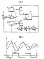
- FIG. 1 shows a block diagram of the exemplary embodiment
- FIG. 2 shows a signal diagram to explain the mode of operation.
- the internal combustion engine with the drive train and drive wheels of a vehicle represent, due to their elastic properties, a structure which can vibrate and which, in the event of interference, e.g. due to a fuel surge, a delayed combustion, or due to an external moment jump (pothole or grooves on the road) can be excited to more or less damped vibrations.
- These vibrations are usually in a frequency range between 2 and 8 Hz and are felt as jerky. This frequency is given by the above-mentioned oscillatory system "motor-drive train-tire-motor vehicle".
- the excitation of the jerky vibrations comes about through time-scattering torque generation of the engine or through different resistance moments of the driven vehicle.
- Various methods for detecting bucking are known from the prior art specified at the outset.
- FIG. 1 shows an internal combustion engine 10 whose fuel injection (signal ti) and ignition timing adjustment (signal CCz) is effected by a map-controlled computer.
- the map with the fuel injection data is stored in the injection computer 11 and the map with the ignition angle data in the ignition computer 12.
- These two computers 11, 12 and, if appropriate, further modules shown in FIG. 1 can of course be combined in a single computer.
- a map-controlled fuel injection and ignition timing adjustment is known for example from DE-OS 28 50 534 (US Pat. No. 4,250,858) and has also been implemented in BMW vehicles since 1978.
- the map-dependent output values for the injection t ik and for the ignition ⁇ zk are in correction stages 13, 14 also have correction functions f1 (p) and f2 (p) applied as a function of parameters.
- the output signals can be influenced additively or multiplicatively. Correction functions such as temperature compensation, start enrichment, acceleration enrichment, overrun cutoff, pressure functions etc. are addressed here, which intervene in a manner known per se in the injection and ignition. This results in a corrected control signal for the injection ti and a corrected control signal for the ignition ⁇ z .
- the internal combustion engine 10 generates a driving torque which is in equilibrium at constant speed with the resistance moments of the vehicle (air resistance, frictional resistance of the tires, the transmission, the driven units and the bearings as well as the acceleration resistance). If either the driving torque of the engine or 'one of the resistance moments of the vehicle is changed, the engine speed changes according to the equations of motion of the mechanics until a torque equilibrium is reached again by increasing or decreasing the speed-dependent resistance moments. Since the main part of the resistance moments occurs on the drive wheels, the respective engine speed, which corresponds to a torque balance, depends on the transmission and rear axle ratio.
- the speed signal n is fed directly and once via a further low-pass filter 17 to a comparison stage 18, the difference signal of which is fed to a jerk correction stage 20 via a sign formation stage 19.
- the output signal acts on the correction stage 14.
- the jerky vibration manifests itself as a speed vibration of the speed n.
- the low-pass filter 17 converts the speed vibration n into a vibration nf.
- a constantly changing sign is obtained at the output of the sign formation stage 19, which changes in accordance with the signal sequence U20.
- the comparison stage 18 together with the sign formation stage 19 can be designed, for example, as a comparator.
- the changing sign now evaluates the factor K in the jerk correction stage 20, which results in an alternating ignition advance and retard according to the signal sequence U20.
- This changing ignition timing is superimposed on the ignition angle ⁇ zk from the map together with any further correction functions f2 (p), which results in an overall ignition angle ⁇ z .
- This changing ignition angle thus counteracts the jerky vibration, ie when the engine speed increases, the torque is reduced by retarding and when the engine speed drops, torque increases by early adjustment. Lies no jerking before, the output signal of the jerk correction stage 20 is zero. The jerky vibration is dampened in the bud by this measure with a suitable choice of the factor K.
- this factor K can be constant.
- Another possibility is to choose two factors K, one of which is effective when adjusted early and the other when adjusted late. Since the torque curve is not linear depending on the firing angle, a compensation can be created in this way depending on the working point.
- an even finer adjustment can be achieved in that the factor K as a function of parameters of the internal combustion engine, e.g. the speed, the temperature and the load of a predefinable function is controlled. In this way, the active jerk damping can be optimized by counter-ignition control. This variation is shown by the broken arrow.
- the timing of the change between early and late adjustment can also be optimized by varying the time constant of the low-pass filter 17. This is also shown by an interrupted arrow.
- passive damping can also be provided. Since the duration of the injection and the ignition angle are directly dependent on the measured speed or load, but these values change dynamically even with the frequency of the jerking vibration when the "Engine " system is excited Feedback takes place, by means of which the jerky vibration itself is excited or amplified with a suitable phase position.
- the load signal t 1 initially formed is therefore filtered in the low-pass filter 16. This is preferably done by suitable averaging, the time constant being adapted to the jerking vibration.
- a corrected load signal t lf is fed to the computers 11, 12 for processing.
- optimization can take place by influencing the time constant of the low-pass filter as a function of parameters. It is also possible to filter the speed signal n by a low-pass filter itself.
- the anti-jerking measures are advantageously rendered ineffective by influencing the ignition and injection, since, on the one hand, there is usually no more jerking in these areas and, on the other hand, undesirable influences, in particular during strong acceleration processes, are avoided.
Landscapes
- Engineering & Computer Science (AREA)
- Chemical & Material Sciences (AREA)
- Combustion & Propulsion (AREA)
- Mechanical Engineering (AREA)
- General Engineering & Computer Science (AREA)
- Theoretical Computer Science (AREA)
- Signal Processing (AREA)
- Electrical Control Of Ignition Timing (AREA)
- Combined Controls Of Internal Combustion Engines (AREA)
- Electrical Control Of Air Or Fuel Supplied To Internal-Combustion Engine (AREA)
- Control Of Vehicle Engines Or Engines For Specific Uses (AREA)
Abstract
Es wird eine Einrichtung zum Dämpfen von vorzugsweise niederfrequenten Ruckelschwingungen bei einer Brennkraftmaschine vorgeschlagen, wobei zur aktiven Dämpfung der Ruckelschwingung der Zündwinkel und daraus resultierend das Drehmoment des Motors in dem Sinne verstellt wird, daß bei einem Drehzahlanstieg die Zündung in Richtung spät (das reultierende Drehmoment verringert) und bei einem Drehzahlabfall die Zündung in Richtung früh (und damit eine Erhöhung des Drehmoments) erfolgt. Durch diese dynamische Kompensation der Ruckelschwingung wird eine schnelle und wirkungsvolle Abhilfe gegen Ruckelschwingungen erreicht. Durch das sehr schnelle Ansprechen dieser Anti-Ruckel-Maßnahme werden Ruckelerscheinungen schon im Keim erstickt. Eine Dämpfung der Ruckelerscheinung wird auch dann erreicht, wenn das anregende System extern d.h. nicht durch die Brennkraftmaschine selbst erfolgt. Die Anti-Ruckel-Maßnahme wirkt sich weder abgas- noch verbrauchsschädlich aus.
Description
Stand der TechnikState of the art
Die Erfindung betrifft eine Einrichtung zum Dämpfen von vorzugsweise niederfrequenten Ruckelschwingungen bei einer Brennkraftmaschine nach der Gattung des Hauptanspruchs. Eine solche Einrichtung ist aus der DE-OS 29 06 782 (US-PS 4 345 559) bekannt. Dort erfolgt ein mit den Ruckelschwingungen synchroner'Eingriff auf das Luft-Kraftstoff-Gemisch, wodurch den Ruckelschwingungen entgegengesteuert wird. Dieses Verfahren hat den Nachteil, daß die Veränderung der Kraftstoffzugabe und deren Auswirkung auf das Drehmoment, bzw. die Drehzahl der Brennkraftmaschine sehr träge und daher nur schwer mit zufriedenstellender Wirkung realisierbar ist. Darüber hinaus ergeben sich Nachteile durch Abgasverschlechterung und Kraftstoffverbrauchserhöhung. Zusätzlich läßt sich über die Einspritzung nur in geringen Grenzen das Drehmoment des Motors beeinflussen, ohne daß durch diesen Eingriff selbst Ruckelschwingungen angeregt werden (Magerbetrieb, Abschalten eines EinspritzVentils).The invention relates to a device for damping preferably low-frequency bucking vibrations in an internal combustion engine according to the preamble of the main claim. Such a device is known from DE-OS 29 06 782 (US Pat. No. 4,345,559). There is an intervention on the air-fuel mixture that is synchronous with the jerking vibrations, thereby counteracting the jerking vibrations. This method has the disadvantage that the change in the addition of fuel and its effect on the torque or the speed of the internal combustion engine is very sluggish and is therefore difficult to achieve with a satisfactory effect. In addition, there are disadvantages due to deterioration in exhaust gas and increased fuel consumption. In addition, the torque of the engine can be influenced only to a limited extent without the injection that even jerky vibrations are excited by this intervention (lean operation, switching off an injection valve).
Weiterhin ist aus der DE-OS 25 10 526 (US-PS 4 178 891) eine Einrichtung zum Dämpfen von Ruckelschwingungen bekannt, bei der neben dem Eingriff auf das Kraftstoff-Luft-Gemisch noch ein Eingriff auf den Zündwinkel vorgenommen wird. Diese Verstellung erfolgt je.doch unabhängig von der Frequenz des Ruckelns einseitig in Richtung später Zündwinkel, wodurch sich zum einen eine Drehmomentverschlechterung ergibt und zum anderen die Dämpfungswirkung nicht an die Bedürfnisse einer aktiven Gegensteuerung (wechselweise Rücknahme und Zunahme des Drehmomentes im Gegentakt zur Ruckelschwingung) ange-. paßt werden kann.Furthermore, from DE-OS 25 10 526 (US-PS 4 178 891) a device for damping bucking vibrations is known, in which, in addition to the intervention in the fuel-air mixture, an intervention in the ignition angle is also carried out. However, this adjustment takes place regardless of the frequency of the jerking on one side in the direction of the later ignition angle, which on the one hand results in a deterioration in torque and, on the other hand, the damping effect does not meet the needs of active countermeasures (alternate withdrawal and increase in torque in opposition to jerky vibration) -. can be fitted.
Die erfindungsgemäße Einrichtung mit den kennzeichnenden Merkmalen des Hauptanspruchs hat demgegenüber den Vorteil, daß mit einfachen Mitteln eine sehr schnelle und wirkungsvolle Gegensteuerung zu den Ruckelschwingungen ergibt. Diese Gegensteuerung paßt sich den Ruckelschwingungen vollständig an und führt daher zu einer sehr schnellen Dämpfung, wobei sich weder eine spürbare Abgasverschlechterung noch eine Verbrauchserhöhung ergibt. Die Beeinflussung über die Zündung ermöglicht eine kontinuierliche, weiche Drehmomentensteuerung, ohne den Verbrennungsablauf ungünstig zu beeinflussen.The device according to the invention with the characterizing features of the main claim has the advantage that simple means result in a very fast and effective countermeasure to the bucking vibrations. This countermeasure adapts completely to the jerking vibrations and therefore leads to very rapid damping, with neither a noticeable deterioration in exhaust gas nor an increase in consumption. The ignition control enables continuous, smooth torque control without adversely affecting the combustion process.
Durch die in den Unteransprüchen aufgeführten Maßnahmen sind vorteilhafte Weiterbildungen und Verbesserungen der im Hauptanspruch angegebenen Einrichtung möglich. Besonders vorteilhaft ist die Ruckelerfassung durch Differenzbildung zwischen dem momentanen Drehzahlsignal und dem über einen Tiefpaß geleiteten Drehzahlsignal. Das Differenzsignal steuert dann direkt die Richtung der Zündzeitpunktverschiebung. Durch Beeinflussung der Zeitkonstanten des Tiefpasses durch Parameter der Brennkraftmaschine kann eine optimale Anpassung der Zündzeitpunktgegensteuerung erreicht werden.Advantageous further developments and improvements of the device specified in the main claim are possible through the measures listed in the subclaims. Especially Another advantage is the jerk detection by forming the difference between the current speed signal and the speed signal conducted via a low-pass filter. The difference signal then directly controls the direction of the ignition timing shift. By influencing the time constant of the low-pass filter through parameters of the internal combustion engine, an optimal adaptation of the ignition timing counter-control can be achieved.
Neben der dynamischen Maßnahme gegen Ruckeln durch synchrone Zündzeitpunktverschiebung und die dadurch erzielbare Drehmomentvariation ist es besonders vorteilhaft, zusätzlich passive Maßnahmen zu ergreifen, wobei insbesondere das der Zündanlage und/oder der Kraftstoffeinspritzanlage zugeführte Lastsignal und/oder Drehzahlsignal über einen weiteren Tiefpaß geführt werden. Dies geschieht vorzugsweise durch geeignete Mittelwertbildung und/oder Filterung der durch die Ruckelschwingungen beeinflußten Parameter, wobei die Zeitkonstante auf die Ruckelschwingung angepaßt ist. Dadurch wird vermieden, daß über die Steuerparameter bereits primär ein Einfluß der Ruckelschwingungen bei der Bildung der Einspritz- und Zünd-Daten zustande kommt.In addition to the dynamic measure against jerking due to a synchronous ignition timing shift and the torque variation that can be achieved thereby, it is particularly advantageous to take passive measures, in particular the load signal and / or speed signal fed to the ignition system and / or the fuel injection system being passed through a further low-pass filter. This is preferably done by suitable averaging and / or filtering of the parameters influenced by the jerking vibrations, the time constant being adapted to the jerking vibrations. This avoids that the control parameters primarily influence the jerky vibrations when forming the injection and ignition data.
Ein Ausführungsbeispiel der Erfindung ist in der Zeichnung dargestellt und in der nachfolgenden Beschreibung näher erläutert. Es zeigen Figur 1 ein Blockschaltbild des Ausführungsbeispiels und Figur 2 ein Signaldiagramm zur Erläuterung der Wirkungsweise.An embodiment of the invention is shown in the drawing and explained in more detail in the following description. FIG. 1 shows a block diagram of the exemplary embodiment and FIG. 2 shows a signal diagram to explain the mode of operation.
Die Brennkraftmaschine mit Antriebsstrang und Antriebsrädern eines Fahrzeugs stellen aufgrund ihrer elastischen Eigenschaften ein schwingfähiges Gebilde dar, das bei Störeinflüssen, z.B. infolge eines Kraftstoffschubs, einer verschleppten Verbrennung, oder aufgrund eines von außen verursachten Momentensprungs (Schlagloch oder Rillen auf der Fahrbahn) zu mehr oder weniger gedämpften Schwingungen angeregt werden kann. Diese Schwingungen liegen in der Regel in einem Frequenzbereich zwischen 2 und 8 Hz und werden als Ruckeln empfunden. Diese Frequenz ist durch das oben bereits erwähnte schwingungsfähige System "Motor-Triebstrang-Reifen-Kraftfahrzeug" gegeben. Die Anregung der Ruckelschwingungen kommt durch zeitlich streuende Drehmomenterzeugung des Motors oder durch unterschiedliche Widerstandsmomente des angetriebenen Fahrzeugs zustande. Verschiedene Methoden zur Ruckelerfassung sind aus dem eingangs angegebenen Stand der Technik bekannt.The internal combustion engine with the drive train and drive wheels of a vehicle represent, due to their elastic properties, a structure which can vibrate and which, in the event of interference, e.g. due to a fuel surge, a delayed combustion, or due to an external moment jump (pothole or grooves on the road) can be excited to more or less damped vibrations. These vibrations are usually in a frequency range between 2 and 8 Hz and are felt as jerky. This frequency is given by the above-mentioned oscillatory system "motor-drive train-tire-motor vehicle". The excitation of the jerky vibrations comes about through time-scattering torque generation of the engine or through different resistance moments of the driven vehicle. Various methods for detecting bucking are known from the prior art specified at the outset.
In Figur 1 ist eine Brennkraftmaschine 10 dargestellt, deren Kraftstoffeinspritzung (Signal ti) und Zündzeitpunktverstellung (Signal CCz) durch einen kennfeldgesteuerten Rechner bewirkt wird. Dabei ist das Kennfeld mit den Kraftstoffeinspritzdaten im Einspritzrechner 11 und das Kennfeld mit den Zündwinkeldaten im Zündungsrechner 12 abgelegt. Diese beiden Rechner 11, 12 sowie gegebenenfalls weitere in Figur 1 dargestellte Baugruppen können natürlich in einem einzigen Rechner zusammengefaßt sein. Eine kennfeldgesteuerte Kraftstoffeinspritzung und Zündzeitpunktverstellung ist beispielsweise aus der DE-OS 28 50 534 (US-PS 4 250 858) bekannt und darüber hinaus in BMW-Fahrzeugen seit dem Jahre 1978 realisiert. Die kennfeldabhängigen Ausgangswerte für die Einspritzung tik und für die Zündung αzk werden in Korrekturstufen 13, 14 noch mit Korrekturfunktionen f1 (p) und f2 (p) in Abhängigkeit von Parametern beaufschlagt. Diese Beeinflussung der Ausgangssignale kann additiv oder multiplikativ erfolgen. Hier sind insbesondere Korrekturfunktionen wie Temperaturkompensationen, Startanreicherung, Beschleunigungsanreicherung, Schubabschaltung, Druckfunktionen usw. angesprochen, die in an sich bekannter Weise in die Einspritzung und Zündung eingreifen. Daraus ergibt sich ein korrigiertes Steuersignal für die Einspritzung ti und ein korrigiertes Steuersignal für die Zündung αz.1 shows an
Die Brennkraftmaschine 10 erzeugt ausgangsseitig ein treibendes_ Drehmoment, das sich bei konstanter Drehzahl mit den Widerstandsmomenten des Fahrzeugs (Luftwiderstand, Reibwiderstand der Reifen, des Getriebes, der angetriebenen Aggregate und der Lager sowie Beschleunigungswiderstand) im Gleichgewicht befindet. Wird entweder das antriebende Drehmoment des Motors oder 'eines der Widerstandsmomente des Fahrzeugs verändert, so erfolgt entsprechend den Bewegungsgleichungen der Mechanik eine Veränderung der Motordrehzahl, bis durch Erhöhen oder Absenken der drehzahlabhängigen Widerstandsmomente erneut ein Momentengleichgewicht erreicht ist. Da der Hauptteil der Widerstandsmomente an den Antriebsrädern auftritt, ist die jeweilige Motordrehzahl, der ein Momentengleichgewicht entspricht, von Getriebe- und Hinterachsübersetzung abhängig.The
Die ermittelte Ausgangsdrehzahlwert n wird sowohl dem Einspritzrechner 11, wie auch dem Zündungsrechner 12 zugeführt. Weiterhin wird dieses Drehzahlsignal n einer Divisionsstufe 15 zugeführt, der zusätzlich ein Luftdurchflußsignal Q zugeführt ist. Durch Division wird ein Lastsignal tl = Q/n gebildet, das über einen Tiefpaß 16 den beiden Rechnern 11, 12 als Lastsignal zugeführt wird.The determined output speed value n is fed to both the injection computer 11 and the
Schließlich wird das Drehzahlsignal n einmal direkt und einmal über einen weiteren Tiefpaß 17 einer Vergleichsstufe 18 zugeführt, deren Differenzsignal über eine Vorzeichen-Bildungsstufe 19 einer Ruckelkorrekturstufe 20 zugeführt ist. Deren Ausgangssignal wirkt auf die Korrekturstufe 14 ein.Finally, the speed signal n is fed directly and once via a further low-pass filter 17 to a comparison stage 18, the difference signal of which is fed to a
Zunächst soll anhand von Figur 2 die dynamische Zünd- .winkelbeeinflussung zur aktiven Dämpfung der Ruckelerscheinung erläutert werden. Die Ruckelschwingung äußert sich als Drehzahlschwingung der Drehzahl n. Durch den Tiefpaß 17 wird die Drehzahlschwingung n in eine Schwingung nf umgewandelt. Durch Differenzbildung der beiden Signalfolgen n und nf erhält man am Ausgang der Vorzeichenbildungsstufe 19 ein ständig wechselndes Vorzeichen, das sich entsprechend der Signalfolge U20 ändert. Die Vergleichsstufe 18 zusammen mit der Vorzeichen-Bildungsstufe 19 können z.B. als Komparator ausgebildet sein. Das wechselnde Vorzeichen bewertet nun den Faktor K in der Ruckelkorrekturstufe 20, wodurch sich eine wechselnde Zündverstellung nach früh und spät gemäß der Signalfolge U20 ergibt. Diese wechselnde Zündverstellung wird dem Zündwinkel αzk aus dem Kennfeld zusammen mit eventuellen weiteren Korrekturfunktionen f2 (p) überlagert, wodurch sich ein gesamter Zündwinkel αz ergibt. Dieser wechselnde Zündwinkel wirkt somit der Ruckelschwingung entgegen, d.h., bei Drehzahlerhöhung erfolgt eine Momentenrücknahme durch Spätverstellung und bei Drehzahlab- si.nken ein Momentenzuwachs durch Frühverstellung. Liegt kein Ruckeln vor, so ist das Ausgangssignal der Ruckelkorrekturstufe 20 gleich Null. Die Ruckelschwingung wird durch diese Maßnahme bei geeigneter Wahl des Faktors K bereits im Keim gedämpft.First, the dynamic ignition angle influence for active damping of the jerking phenomenon is to be explained with reference to FIG. The jerky vibration manifests itself as a speed vibration of the speed n. The low-pass filter 17 converts the speed vibration n into a vibration nf. By forming the difference between the two signal sequences n and nf, a constantly changing sign is obtained at the output of the
Dieser Faktor K kann im einfachsten Fall konstant sein. Eine weitere Möglichkeit besteht in der Wahl zweier Faktoren K, wobei der eine bei der Verstellung nach früh und der andere bei der Verstellung nach spät wirksam wird. Da der Momentenverlauf in Abhängigkeit vom Zündwinkel nicht linear ist, kann auf diese Weise je nach Arbeitspunkt ein Ausgleich geschaffen werden. Schließlich kann eine noch feinere Anpassung dadurch erreicht werden, daß der Faktor K in Abhängigkeit von Parametern der Brennkraftmaschine, wie z.B. der Drehzahl, der Temperatur und der Last einer-vorgebbaren Funktion gesteuert wird. Auf diese Weise kann die aktive RuckeLdämpfung durch Zündungsgegensteuerung optimiert werden. Diese Variation ist durch den unterbrochenen Pfeil dargestellt.In the simplest case, this factor K can be constant. Another possibility is to choose two factors K, one of which is effective when adjusted early and the other when adjusted late. Since the torque curve is not linear depending on the firing angle, a compensation can be created in this way depending on the working point. Finally, an even finer adjustment can be achieved in that the factor K as a function of parameters of the internal combustion engine, e.g. the speed, the temperature and the load of a predefinable function is controlled. In this way, the active jerk damping can be optimized by counter-ignition control. This variation is shown by the broken arrow.
Neben dem Betrag der ZündzeitpunktverstellungA α zar zur Ruckelgegensteuerung kann auch der Zeitpunkt des Wechselns zwischen Früh- und Spätverstellung durch Variation der Zeitkonstanten des Tiefpasses 17 optimiert werden. Dies ist ebenfalls durch einen unterbrochenen Pfeil dargestellt.In addition to the amount of the ignition timing adjustment A α zar for bucking counter-control, the timing of the change between early and late adjustment can also be optimized by varying the time constant of the low-pass filter 17. This is also shown by an interrupted arrow.
Neben der beschriebenen aktiven Dämpfung der Ruckelerscheinungen kann noch zusätzlich eine passive Dämpfung vorgesehen werden. Da die Dauer der Einspritzung und der Zündwinkel direkt von der gemessenen Drehzahl, bzw. Last abhängen, diese Größen jedoch selbst mit der Frequenz der Ruckelschwingung bei angeregtem System "Motor ..." ihren Wert dynamisch ändern, kann eine Rückkopplung erfolgen, durch die bei geeigneter Phasenlage die Ruckelschwingung selbst angeregt bzw. verstärkt wird. Zur Bildung des Lastsignals für die Rechner 11, 12 wird daher das zunächst gebildete Lastsignal t1 im Tiefpaß 16 gefiltert. Dies geschieht vorzugsweise durch geeignete Mittelwertbildung, wobei die Zeitkonstante auf die Ruckelschwingung angepaßt wird. Durch Filterung mit Tiefpaßcharakter wird ein korrigiertes Lastsignal tlf zur Verarbeitung den Rechnern 11, 12 zugeführt. Auch hier kann wiederum durch parameterabhängige Beeinflussung der Zeitkonstante des Tiefpasses eine Optimierung erfolgen. Weiterhin ist es möglich, das Drehzahlsignal n selbst ebenfalls durch einen Tiefpaß zu filtern.In addition to the active damping of the jerking phenomena described, passive damping can also be provided. Since the duration of the injection and the ignition angle are directly dependent on the measured speed or load, but these values change dynamically even with the frequency of the jerking vibration when the "Engine ..." system is excited Feedback takes place, by means of which the jerky vibration itself is excited or amplified with a suitable phase position. To form the load signal for the
Es sei noch festgehalten, daß anstelle der Ruckelerfassung durch Vergleich des Drehzahlsignals mit einem über einen Tiefpaß gefilterten Drehzahlsignal auch der Vergleich des Drehzahlsignals mit einem gemittelten Drehzahlsignal treten kann.It should also be noted that instead of juddering by judging the speed signal with a speed signal filtered via a low-pass filter, the comparison of the speed signal with an averaged speed signal can also occur.
Oberhalb einer festlegbaren Last bzw. oberhalb einer vorgebbaren Drehzahl werden vorteilhaft die Antiruckelmaßnahmen durch Beeinflussung von Zündung und Einspritzung unwirksam gemacht, da zum einen in diesen Bereichen gewöhnlich kein Ruckeln mehr auftritt und zum anderen unerwünschte Beeinflussungen, insbesondere bei starken Beschleunigungsvorgängen, vermieden werden.Above a definable load or above a specifiable speed, the anti-jerking measures are advantageously rendered ineffective by influencing the ignition and injection, since, on the one hand, there is usually no more jerking in these areas and, on the other hand, undesirable influences, in particular during strong acceleration processes, are avoided.
Die beschriebenen Maßnahmen zur Vermeidung von Ruckeln können natürlich in beliebiger Weise mit bekannten Anti-Ruckel-Maßnahmen kombiniert werden. Dies betrifft insbesondere auch diejenigen Maßnahmen, die im eingangs angegebenen Stand der Technik beschrieben' sind.The described measures to avoid jerking can of course be combined in any way with known anti-jerking measures. This applies in particular to those measures which are described in the prior art specified at the outset.
Claims (9)
Applications Claiming Priority (2)
| Application Number | Priority Date | Filing Date | Title |
|---|---|---|---|
| DE3243235 | 1982-11-23 | ||
| DE19823243235 DE3243235A1 (en) | 1982-11-23 | 1982-11-23 | DEVICE FOR DAMPING VIBRATION VIBRATIONS IN AN INTERNAL COMBUSTION ENGINE IN A MOTOR VEHICLE |
Publications (3)
| Publication Number | Publication Date |
|---|---|
| EP0109545A2 true EP0109545A2 (en) | 1984-05-30 |
| EP0109545A3 EP0109545A3 (en) | 1985-01-16 |
| EP0109545B1 EP0109545B1 (en) | 1989-01-18 |
Family
ID=6178783
Family Applications (1)
| Application Number | Title | Priority Date | Filing Date |
|---|---|---|---|
| EP83110297A Expired EP0109545B1 (en) | 1982-11-23 | 1983-10-15 | Device to damp out the juddering of an internal-combustion engine |
Country Status (4)
| Country | Link |
|---|---|
| US (1) | US4527523A (en) |
| EP (1) | EP0109545B1 (en) |
| JP (1) | JPS59113269A (en) |
| DE (2) | DE3243235A1 (en) |
Cited By (6)
| Publication number | Priority date | Publication date | Assignee | Title |
|---|---|---|---|---|
| EP0337491A1 (en) * | 1988-04-15 | 1989-10-18 | Hitachi, Ltd. | Apparatus and method for controlling ignition timing of internal combustion engines |
| WO1992001152A1 (en) * | 1990-07-05 | 1992-01-23 | Robert Bosch Gmbh | Device for preventing jerky operation in motor vehicles |
| GB2253440A (en) * | 1991-03-06 | 1992-09-09 | Bosch Gmbh Robert | Ignition control circuit for the prevention of engine speed oscillations during load changes |
| EP0273601B1 (en) * | 1986-12-09 | 1993-01-13 | LUCAS INDUSTRIES public limited company | Engine control and combustion quality detection system and method |
| EP0500107A3 (en) * | 1991-02-20 | 1994-05-11 | Nippon Denso Co | Spark timing control system for a vehicle-driving internal combustion engine |
| EP0655554A1 (en) * | 1993-11-30 | 1995-05-31 | Société Anonyme dite: REGIE NATIONALE DES USINES RENAULT | Method of correction of torque jerks of an internal combustion engine |
Families Citing this family (38)
| Publication number | Priority date | Publication date | Assignee | Title |
|---|---|---|---|---|
| IT1179959B (en) * | 1984-02-08 | 1987-09-23 | Fiat Auto Spa | METHOD AND DEVICE FOR THE AUTOMATIC CORRECTION OF THE FUEL RATIO IN AN ALTERNATIVE ENDOTHERMAL ENGINE |
| DE3414681A1 (en) * | 1984-04-18 | 1985-10-24 | Robert Bosch Gmbh, 7000 Stuttgart | METHOD AND DEVICE FOR INJECTING TIME CONTROL IN INTERNAL COMBUSTION ENGINES |
| JPS6267258A (en) * | 1985-09-20 | 1987-03-26 | Hitachi Ltd | Internal combustion engine operation control method |
| JP2511862B2 (en) * | 1986-01-08 | 1996-07-03 | 株式会社日立製作所 | Ignition timing control method for internal combustion engine |
| JPH089981B2 (en) * | 1986-01-23 | 1996-01-31 | 日産自動車株式会社 | Engine noise reduction device |
| JPH081165B2 (en) * | 1986-05-23 | 1996-01-10 | 株式会社日立製作所 | Ignition timing control method and apparatus for internal combustion engine |
| DE3738719C2 (en) * | 1986-11-27 | 1997-09-25 | Volkswagen Ag | Method and arrangement for preventing disturbing load changes in a vehicle internal combustion engine |
| JPH07117023B2 (en) * | 1986-12-04 | 1995-12-18 | 株式会社日立製作所 | Engine controller |
| JPS63154862A (en) * | 1986-12-17 | 1988-06-28 | Mitsubishi Electric Corp | Electronic control device for internal combustion engine |
| JPS63212740A (en) * | 1987-02-27 | 1988-09-05 | Mitsubishi Electric Corp | Electronic controller for internal combustion engine |
| US4724813A (en) * | 1987-03-10 | 1988-02-16 | General Motors Corporation | Internal combustion engine with dilution reduction in response to surge detection |
| JPS63227957A (en) * | 1987-03-17 | 1988-09-22 | Japan Electronic Control Syst Co Ltd | Internal combustion engine ignition timing control device |
| JPH076480B2 (en) * | 1987-03-26 | 1995-01-30 | 株式会社ユニシアジェックス | Ignition timing control device for internal combustion engine |
| GB2208410B (en) * | 1987-08-01 | 1991-07-17 | Ford Motor Co | Engine calibration |
| US4928652A (en) * | 1987-09-17 | 1990-05-29 | Mazda Motor Corporation | Engine control system for suppressing car body vibration |
| JP2585312B2 (en) * | 1987-11-09 | 1997-02-26 | 日産自動車株式会社 | Ignition timing control device for internal combustion engine |
| EP0447393B1 (en) * | 1988-12-06 | 1994-06-01 | Robert Bosch Gmbh | Method and apparatus for controlling the torque of an engine |
| US5016593A (en) * | 1989-05-01 | 1991-05-21 | Toyota Jidosha Kabushiki Kaisha | Method and apparatus for preventing surging of vehicle having internal combustion engine |
| DE4201861C1 (en) * | 1992-01-24 | 1993-02-04 | Robert Bosch Gmbh, 7000 Stuttgart, De | Detecting and suppression circuitry for speed changes and jerking vibrations of IC engine - uses microprocessor to register difference in changes of sequential RPM measurement values to distinguish between jerk and desired constant acceleration |
| DE4222298B4 (en) * | 1992-07-08 | 2005-11-03 | Robert Bosch Gmbh | Method for damping occurring jerking vibrations for internal combustion engines |
| JP2550290B2 (en) * | 1994-01-28 | 1996-11-06 | 株式会社日立製作所 | Ignition timing control method and apparatus for internal combustion engine |
| US5560336A (en) * | 1994-03-11 | 1996-10-01 | Nissan Motor Co., Ltd. | Apparatus and method for estimating stability factor of combustion applicable to vehicular internal combustion engine |
| DE19523898B4 (en) * | 1995-06-30 | 2006-05-11 | Robert Bosch Gmbh | Method and device for controlling the drive screen unit of a motor vehicle |
| DE19733472C2 (en) * | 1997-08-02 | 1999-08-05 | Daimler Chrysler Ag | Method for preventing jerky vibrations during positive and negative acceleration of motor vehicles |
| DE19958251C2 (en) | 1999-12-03 | 2002-11-21 | Siemens Ag | Method for damping mechanical vibrations in the drive train of an internal combustion engine |
| DE10038339A1 (en) * | 2000-08-05 | 2002-02-14 | Bosch Gmbh Robert | Method and device for monitoring a sensor |
| US20030168028A1 (en) * | 2000-10-12 | 2003-09-11 | Kaibushiki Kaisha Moric | Oil control device for two-stroke engine |
| US6895908B2 (en) * | 2000-10-12 | 2005-05-24 | Kabushiki Kaisha Moric | Exhaust timing controller for two-stroke engine |
| US6832598B2 (en) | 2000-10-12 | 2004-12-21 | Kabushiki Kaisha Moric | Anti-knocking device an method |
| US6892702B2 (en) * | 2000-10-12 | 2005-05-17 | Kabushiki Kaisha Moric | Ignition controller |
| JP2003056437A (en) * | 2001-08-10 | 2003-02-26 | Moric Co Ltd | Engine control method and system for small vehicle |
| US6589135B2 (en) * | 2001-08-21 | 2003-07-08 | Deere & Company | System and method for reducing vehicle bouncing |
| DE10147589B4 (en) * | 2001-09-27 | 2011-01-27 | Volkswagen Ag | Method for operating an internal combustion engine |
| DE10206197A1 (en) * | 2002-02-15 | 2003-09-04 | Daimler Chrysler Ag | Reducing load change impact for vehicle with sub-frame involves accelerating the sub-frame during acceleration and braking it before it impacts on the body |
| DE102007011740A1 (en) * | 2007-03-10 | 2008-09-11 | Bayerische Motoren Werke Aktiengesellschaft | System for reducing critical vibration in motorcycle suspension systems comprises control unit sending signals to actuator when critical vibration begins, actuator then producing damping vibrations, e.g. by cyclic variation of drive torque |
| CN106545452B (en) * | 2016-09-30 | 2018-07-06 | 华北水利水电大学 | A kind of oil/CNG dual fuel engine electronic spark advance devices and advance angle control optimization method |
| DE102017220328A1 (en) * | 2017-11-15 | 2019-05-16 | Robert Bosch Gmbh | Vibration damping arrangement for injection systems of motor vehicles, in particular for fuel injection systems, and injection system with such a vibration damping arrangement |
| JP7020088B2 (en) * | 2017-12-06 | 2022-02-16 | トヨタ自動車株式会社 | Internal combustion engine control device |
Family Cites Families (18)
| Publication number | Priority date | Publication date | Assignee | Title |
|---|---|---|---|---|
| DE1125230B (en) * | 1960-09-23 | 1962-03-08 | Paul H Schweitzer | Self-regulation of internal combustion engines |
| US3789816A (en) * | 1973-03-29 | 1974-02-05 | Bendix Corp | Lean limit internal combustion engine roughness control system |
| US4178891A (en) * | 1975-03-11 | 1979-12-18 | Robert Bosch Gmbh | Method and apparatus for controlling the operation of an internal combustion engine |
| DE2510526C2 (en) * | 1975-03-11 | 1984-11-29 | Robert Bosch Gmbh, 7000 Stuttgart | Method for regulating the operating behavior of an internal combustion engine |
| JPS5713898Y2 (en) * | 1977-06-17 | 1982-03-20 | ||
| US4197767A (en) * | 1978-05-08 | 1980-04-15 | The Bendix Corporation | Warm up control for closed loop engine roughness fuel control |
| DE2961307D1 (en) * | 1978-08-09 | 1982-01-14 | Bosch Gmbh Robert | Ignition and fuel injection control system for internal combustion engines |
| DE2906782A1 (en) * | 1979-02-22 | 1980-09-04 | Bosch Gmbh Robert | DEVICE FOR DAMPING VIBRATION VIBRATIONS IN AN INTERNAL COMBUSTION ENGINE |
| EP0016548B1 (en) * | 1979-03-14 | 1984-12-27 | LUCAS INDUSTRIES public limited company | Fuel control system for an internal combustion engine |
| DE2949307C2 (en) * | 1979-12-07 | 1983-12-15 | Bosch und Pierburg System oHG, 4040 Neuss | Method and device for changing the interval between ignition control pulses emitted by an ignition pulse generator |
| US4337647A (en) * | 1979-12-07 | 1982-07-06 | The Bendix Corporation | Engine roughness sensor |
| DE2951755A1 (en) * | 1979-12-21 | 1981-07-02 | Alfred Teves Gmbh, 6000 Frankfurt | METHOD AND CIRCUIT ARRANGEMENT FOR CONVERTING VARIABLE PHYSICAL VALUES PRESENTING IN FREQUENCY AND PRESENTED AS A FREQUENCY. SIGNALS |
| JPS56115855A (en) * | 1980-02-19 | 1981-09-11 | Toyota Motor Corp | Method and apparatus for controlling ignition timing of engine |
| DE3111135A1 (en) * | 1980-06-20 | 1982-03-11 | Robert Bosch Gmbh, 7000 Stuttgart | METHOD FOR CONTROLLING THE COMBUSTION IN THE COMBUSTION ROOMS OF AN INTERNAL COMBUSTION ENGINE |
| JPS5738642A (en) * | 1980-08-19 | 1982-03-03 | Nippon Denso Co Ltd | Method of internal-combustion engine control |
| JPS5945832B2 (en) * | 1980-09-29 | 1984-11-08 | 日産自動車株式会社 | Ignition timing control device |
| JPS57206748A (en) * | 1981-06-12 | 1982-12-18 | Nissan Motor Co Ltd | Deciding method of engine required value in electronic controller |
| JPS5848738A (en) * | 1981-09-16 | 1983-03-22 | Toyota Motor Corp | Apparatus for suppressing and controlling vibration of vehicle |
-
1982
- 1982-11-23 DE DE19823243235 patent/DE3243235A1/en not_active Withdrawn
-
1983
- 1983-10-15 DE DE8383110297T patent/DE3378985D1/en not_active Expired
- 1983-10-15 EP EP83110297A patent/EP0109545B1/en not_active Expired
- 1983-10-26 US US06/545,531 patent/US4527523A/en not_active Expired - Lifetime
- 1983-11-08 JP JP58208409A patent/JPS59113269A/en active Granted
Cited By (9)
| Publication number | Priority date | Publication date | Assignee | Title |
|---|---|---|---|---|
| EP0273601B1 (en) * | 1986-12-09 | 1993-01-13 | LUCAS INDUSTRIES public limited company | Engine control and combustion quality detection system and method |
| EP0337491A1 (en) * | 1988-04-15 | 1989-10-18 | Hitachi, Ltd. | Apparatus and method for controlling ignition timing of internal combustion engines |
| WO1992001152A1 (en) * | 1990-07-05 | 1992-01-23 | Robert Bosch Gmbh | Device for preventing jerky operation in motor vehicles |
| EP0500107A3 (en) * | 1991-02-20 | 1994-05-11 | Nippon Denso Co | Spark timing control system for a vehicle-driving internal combustion engine |
| GB2253440A (en) * | 1991-03-06 | 1992-09-09 | Bosch Gmbh Robert | Ignition control circuit for the prevention of engine speed oscillations during load changes |
| GB2253440B (en) * | 1991-03-06 | 1995-01-04 | Bosch Gmbh Robert | Circuit arrangement for the prevention of rotational-speed oscillations |
| DE4107115C2 (en) * | 1991-03-06 | 2001-06-07 | Bosch Gmbh Robert | Device for controlling the ignition angle of an internal combustion engine |
| EP0655554A1 (en) * | 1993-11-30 | 1995-05-31 | Société Anonyme dite: REGIE NATIONALE DES USINES RENAULT | Method of correction of torque jerks of an internal combustion engine |
| FR2713286A1 (en) * | 1993-11-30 | 1995-06-09 | Renault | Method for correcting torque surges of an internal combustion engine |
Also Published As
| Publication number | Publication date |
|---|---|
| JPH0551791B2 (en) | 1993-08-03 |
| US4527523A (en) | 1985-07-09 |
| EP0109545A3 (en) | 1985-01-16 |
| DE3378985D1 (en) | 1989-02-23 |
| JPS59113269A (en) | 1984-06-29 |
| EP0109545B1 (en) | 1989-01-18 |
| DE3243235A1 (en) | 1984-05-24 |
Similar Documents
| Publication | Publication Date | Title |
|---|---|---|
| EP0109545B1 (en) | Device to damp out the juddering of an internal-combustion engine | |
| DE4391898C2 (en) | Method for controlling number of revolutions of internal combustion engine at idle | |
| DE69827722T2 (en) | Device for controlling the fuel injection of a direct injection gasoline engine and method therefor. | |
| DE19527218B4 (en) | Method and device for regulating the smooth running of an internal combustion engine | |
| DE3717368C2 (en) | Device for damping jerky vibrations in motor vehicles | |
| DE102014010106B4 (en) | Vehicle control system | |
| DE19709395C2 (en) | Knock control method in multi-cylinder internal combustion engines | |
| EP0155993B1 (en) | System for reducing instabilities in vehicle acceleration dynamics | |
| DE19523898B4 (en) | Method and device for controlling the drive screen unit of a motor vehicle | |
| EP0678163B1 (en) | Process for the adaptive knock control of an internal combustion engine | |
| EP0286644B1 (en) | Process for electronic determination of the quantity of fuel of an internal combustion engine | |
| EP0167652B1 (en) | Control apparatus for a vehicle | |
| EP1028242B1 (en) | Method and apparatus for damping vibration type vehicle movements | |
| DE4013943C2 (en) | ||
| DE3805823C3 (en) | Electronic control for an internal combustion engine | |
| DE69511481T2 (en) | Method and device for controlling the ignition timing for an internal combustion engine | |
| DE112010005933B4 (en) | Control device for an internal combustion engine | |
| DE69318797T2 (en) | Device for damping mechanical vibrations in a motor vehicle | |
| DE19547717A1 (en) | Method of alleviating load-change reaction in motor vehicle | |
| DE4222298B4 (en) | Method for damping occurring jerking vibrations for internal combustion engines | |
| DE3007336A1 (en) | DEVICE FOR KNOCKING CONTROL OF AN INTERNAL COMBUSTION ENGINE | |
| DE3930487A1 (en) | DEVICE AND METHOD FOR CONTROLLING THE IGNITION TIMING SETTING FOR AN INTERNAL COMBUSTION ENGINE | |
| DE102005014920A1 (en) | Method to adjust injection times of individual cylinders of an internal combustion engine depending on their dimensions derived from the crank shaft rotations to compensate for fluctuations in injection quantities | |
| DE3742909C2 (en) | ||
| DE68916566T2 (en) | Slip excess control device for driven wheels. |
Legal Events
| Date | Code | Title | Description |
|---|---|---|---|
| PUAI | Public reference made under article 153(3) epc to a published international application that has entered the european phase |
Free format text: ORIGINAL CODE: 0009012 |
|
| 17P | Request for examination filed |
Effective date: 19831015 |
|
| AK | Designated contracting states |
Designated state(s): DE FR GB |
|
| PUAL | Search report despatched |
Free format text: ORIGINAL CODE: 0009013 |
|
| AK | Designated contracting states |
Designated state(s): DE FR GB |
|
| 17Q | First examination report despatched |
Effective date: 19860709 |
|
| GRAA | (expected) grant |
Free format text: ORIGINAL CODE: 0009210 |
|
| AK | Designated contracting states |
Kind code of ref document: B1 Designated state(s): DE FR GB |
|
| GBT | Gb: translation of ep patent filed (gb section 77(6)(a)/1977) | ||
| REF | Corresponds to: |
Ref document number: 3378985 Country of ref document: DE Date of ref document: 19890223 |
|
| ET | Fr: translation filed | ||
| PLBE | No opposition filed within time limit |
Free format text: ORIGINAL CODE: 0009261 |
|
| STAA | Information on the status of an ep patent application or granted ep patent |
Free format text: STATUS: NO OPPOSITION FILED WITHIN TIME LIMIT |
|
| 26N | No opposition filed | ||
| PGFP | Annual fee paid to national office [announced via postgrant information from national office to epo] |
Ref country code: GB Payment date: 20010926 Year of fee payment: 19 |
|
| PGFP | Annual fee paid to national office [announced via postgrant information from national office to epo] |
Ref country code: FR Payment date: 20011017 Year of fee payment: 19 |
|
| PGFP | Annual fee paid to national office [announced via postgrant information from national office to epo] |
Ref country code: DE Payment date: 20011211 Year of fee payment: 19 |
|
| REG | Reference to a national code |
Ref country code: GB Ref legal event code: IF02 |
|
| PG25 | Lapsed in a contracting state [announced via postgrant information from national office to epo] |
Ref country code: GB Free format text: LAPSE BECAUSE OF NON-PAYMENT OF DUE FEES Effective date: 20021015 |
|
| PG25 | Lapsed in a contracting state [announced via postgrant information from national office to epo] |
Ref country code: DE Free format text: LAPSE BECAUSE OF NON-PAYMENT OF DUE FEES Effective date: 20030501 |
|
| GBPC | Gb: european patent ceased through non-payment of renewal fee |
Effective date: 20021015 |
|
| PG25 | Lapsed in a contracting state [announced via postgrant information from national office to epo] |
Ref country code: FR Free format text: LAPSE BECAUSE OF NON-PAYMENT OF DUE FEES Effective date: 20030630 |
|
| REG | Reference to a national code |
Ref country code: FR Ref legal event code: ST |