EP0109555A2 - Armoire de commutation électrique - Google Patents
Armoire de commutation électrique Download PDFInfo
- Publication number
- EP0109555A2 EP0109555A2 EP83110461A EP83110461A EP0109555A2 EP 0109555 A2 EP0109555 A2 EP 0109555A2 EP 83110461 A EP83110461 A EP 83110461A EP 83110461 A EP83110461 A EP 83110461A EP 0109555 A2 EP0109555 A2 EP 0109555A2
- Authority
- EP
- European Patent Office
- Prior art keywords
- locking
- cabinet according
- disk
- rail
- insert
- Prior art date
- Legal status (The legal status is an assumption and is not a legal conclusion. Google has not performed a legal analysis and makes no representation as to the accuracy of the status listed.)
- Granted
Links
Images




Classifications
-
- H—ELECTRICITY
- H02—GENERATION; CONVERSION OR DISTRIBUTION OF ELECTRIC POWER
- H02B—BOARDS, SUBSTATIONS OR SWITCHING ARRANGEMENTS FOR THE SUPPLY OR DISTRIBUTION OF ELECTRIC POWER
- H02B1/00—Frameworks, boards, panels, desks, casings; Details of substations or switching arrangements
- H02B1/26—Casings; Parts thereof or accessories therefor
- H02B1/30—Cabinet-type casings; Parts thereof or accessories therefor
- H02B1/32—Mounting of devices therein
- H02B1/34—Racks
- H02B1/36—Racks with withdrawable units
Definitions
- the invention relates to an electrical switchgear cabinet with at least one slide-in compartment provided with a shelf formed by a sheet metal part, into which at least one slide-in slot has a base part, side walls, a front wall and a rear wall and is equipped with at least one switching device to be operated from the front wall can be introduced.
- a number of switch cabinets have become known, on which slots are formed by attaching floor panels to the frame profiles.
- slide-ins can be inserted which are factory-fitted with the appropriate switching, control and / or regulating devices desired by the customer.
- the slide-in module When operating the control cabinet, it must be required that the slide-in module be fixed in three positions can, a first position, in which both the control connections and the power connections are live, in a second position, a so-called test position, in which only the control connections are still live, but the power connections are already disconnected, and possibly in one third position, the so-called disconnected position, in which both the control connections and. the power connections are also separated from the contacts on the rear, fixed to the switch cabinet, in which work can be carried out on the plug-in unit.
- the rear contacts can only be disconnected when the switchgear is switched off, e.g. when the circuit breaker is switched off, in order to prevent the rear power contacts from being separated from one another under voltage, which leads to arcing and damage to the Control cabinet; It is also required that in certain positions, e.g. in the test position, there is an interlock that prevents the switching device from being switched on.
- the object of the invention is to provide a control cabinet of the type mentioned in the introduction, in which the guidance of the plug-ins, their locking on the one hand and their drive for the switching device on the other hand interact with one another.
- the first gear that is the gear used for locking or unlocking, can have the features of claim 9.
- the transmission lever that can be used can be designed in accordance with the characterizing features of claim 10.
- the drive disk of the transmission can be designed as a locking disk according to the characterizing features of claim 11.
- the locking roller which is set in rotation by the gear mechanism, can advantageously have a groove on the circumference, the radial length of which corresponds to the width of the strip on the rail, so that the locks In a middle position, the roller comes free from the bar, in which the groove contour runs entirely outside the bar, whereas it engages in recesses on the bar in the two positions lying to the side.
- the particular advantage of the arrangement according to the invention is that the locking and the drive for the switch form a unit with one another; so that simultaneous actuation of the drive for the switching device and the locking with the risk that the switching device can also be operated in so-called forbidden positions of the insert is prevented, the possibility of connection or combination by guiding the insert on the rail drive for the switch and locking is made possible.
- the switch button is used in the so-called free position, that is, in the position in which the compression spring relaxes to push the coupling elements apart and the coupling is disengaged, only for actuating the locking device, so that the switching device cannot be switched.
- the switch button can only be actuated and pressed in only in a certain position of the locking gear, in which the pin on the control shaft is aligned with the slot in the mounting or guide wall, so that the clutch is coupled between the two control shafts and the locking drive is virtually uncoupled be, so that only the drive of the switching device is operated.
- the pin In the position in which the switch button is used only to actuate the lock, the pin is positively connected to the drive disk for the locking gear.
- the pin is pressed through the intermediate wall into the engaged position, the positive connection between the drive pulley and the first switch shaft is released because the pin disengages from the drive pulley of the locking mechanism, so that the first control shaft is opposite to that of the catch spring held drive pulley is easily rotatable.
- the switch button can be turned again in the direction in which the locking roller can be screwed in from the other side into the second recess lying on the other side opposite the first recess.
- the power contacts that have become de-energized due to the switching device being left out are in a disconnected position, a so-called test position, against which the control contacts are still engaged.
- the locking mechanism can be turned back to the "slide-in mode" position and the slide-in can be pulled out completely.
- the switch or the switching device can, of course, be switched when the insert is completely removed, since the locking roller and thus the locking gear can be freely rotated.
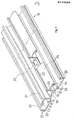
- FIG. 1 shows the bottom part 10 of an insert shown in FIG. 14.
- the base part 10 is supplemented by side walls, front and rear walls to form an insert. It has two support areas 12 and 14 which are arranged at a distance from one another and lie in one plane and are connected via a C-shaped intermediate part 16 to a groove 18 which is arranged in the middle and is open at the bottom.
- On the upper side of the connection area 16 two strips 19 and 20 are formed at a distance from each other, the free ends 21 and 22 of which are angled outwards, thereby forming the snap-on area of a top-hat rail.
- the free end edges 21 and 22 are parallel to the areas 12 and 14 and facing away from each other shoulder strips 23 and 24 are provided, the free end edges are bent and thereby form a circular circular opening 25 and 26 into which screws can be screwed, the Serve bracket of the front and rear walls.
- the part between the area 12 or 14 and the extension strips 23 and 24 can be used as a cable duct.
- the edges of the bottom regions 12 and 14 lying on both sides are included a C-shaped profile 27 and 28 which is open to the outside and which is used for inserting and holding side walls, not shown.
- the groove 18 has a recess 29 in its front half, the task of which is explained below.
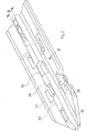
- FIG. 2 shows a rail 31 which is placed on a base plate 30 mounted in the control cabinet (see also FIG. 3) and which is formed from plastic and on which the base part 10 of the relevant slide-in unit can slide.
- a floor panel can be designed and supported, for example, as described in applicant's patent application P ... (Mp.-Nr. 664/82).
- the rail 31 has a bottom region 32, in the central portion of which a raised bar 33 is formed, which extends over the entire length of the rail 32.
- the bar 32 has two lateral recesses 34 on one side and 35 on the other side of the bar 33, which are used for locking, as will be explained in more detail below.
- Spring strips 36 and 37 are formed on the two edges of the base area and, when the insert is to be inserted, should engage in the grooves 17 and 15 of the base part 10, respectively. By interaction of the spring strips 36 and 37 with the grooves 15 and 17 and the strip 33 with the groove 18, the bottom part 10 is thus guided on the rail 31.
- the rail has a downwardly open recess 44, in which a spiral spring 45 is held, which projects above the bar 31 and touches the bottom part 10 when the insert is inserted.
- the base part 10 can then have recesses' (not shown further) in the groove base of the groove 18, into which the tip 46 of the tongue can engage; this causes a latching.
- the spring 45 is V-shaped, the leg ends 47 and 48 being bent inwards.
- the V-shape is also adapted to the recess 44. It is penetrated by a transverse web 49 which is intended to hold the spring 45.
- the recess 44 is delimited on both sides by walls 50 and 51, as a result of which upwardly open recesses 52 and 53 are formed, the latter serving essentially only to save weight.
- the rail according to FIG. 2 is placed on the base plate 30 and held there, the tip 46 of the spring 45 projecting above the bar 33. 1, in which, as mentioned above, the spring strips 36 and 37 engage in the grooves 17 and 15 and the strip 33 in the groove 18.
- the rail is tapered towards the front, the bottom area being chamfered on both sides and the bar 33 sloping towards the front.
- the spring 45 serves to ground the insert by connecting the base part 10 of the insert to the base plate 30 in an electrical-galvanic manner.
- FIG. 11 There is shown a drive for a lock, which is used to lock the insert in the operating position and in the test position.
- the strips 19 and 20 on which the attachment strips 23 and 24 are integrally formed can be seen in FIG.
- the circular opening 26 can be clearly seen, which is formed by bending the end edge of the extension bar 24.
- the end edge is not completely bent into a full circle, but leaves an inward-facing opening 54 free, but a projection 55 is provided on the underside of the extension bar 24, which further complements the circular opening to form a circle.
- the bottom part is made by extrusion or extrusion; the opening 54 is tool-related.
- the ends 21 and 22 can be seen at the free ends of the strips 19 and 20.
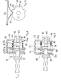
- the locking drive has a locking disk 60 (see also FIGS. 8 to 10) which has a central bore 61 and an eccentric bore 62.
- a slot 63 connects to the central bore 61, the mode of operation of which is also to be explained in more detail below.
- a transfer lever 64 which is supported on a fixed axis 65, is articulated on the eccentric bore 62.
- the transmission lever has a first elongated hole 66 in the region of its bearing point and a second elongated hole 67 at its end opposite from the articulation point at the eccentric bore 62.
- the two elongated holes 66 and 67 lie on the same line with their central axis and are aligned with the central axis of the Articulation point at 62.
- the elongated hole 67 is penetrated by a pin 68 which is firmly connected to a tab 69. 4 to 6 it can be seen that with the tab 69 a Locking wheel 70 is fixedly connected, which in the extension of the center line or center axis of the tab 69 has a recess 71, the circumferential length L corresponds to the width B of the bar 33. 11 are. entered two positions of the transmission lever and the tab 69, namely a thick extended position, which corresponds to that according to FIG. 4, and a dash-dot-drawn position, which corresponds to the position according to FIG. 6.
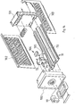
- the insert is formed from the base part 10, a front wall 100, a rear wall 101, two side walls 102 and 103, the locking system being designated 104 overall. This locking is shown in FIGS. 4 to 6 and 11 in more detail.
- the locking wheel or locking roller 70 is connected to the tab 69 via an axis, since it is covered by a cover 105 and is also guided.
- the cover 105 forms a unit with the bracket 72. In the assembled state, the roller extends through the recess 29 and projects downward into the interior of the groove 18 (see also FIG. 14).
- the locking disk 60 with the eccentric bore 62 is mounted on a shift shaft 72 or is mounted displaceably.
- a pin 73 running perpendicular to the shaft 72 is fastened to the switch shaft 72.
- the locking disk 60 has the slot 63 in which the pin 73 can engage in the position shown in FIGS. 8 and 7.
- the selector shaft 72 is pulled out, and the pin 73, which passes through the shaft 72 and is fixed in it by press fit, sits completely in the slot 63.
- the selector shaft extends through a wall 74 connected to the bracket 72 in a manner not shown, through a bore 75 (Fig. 7), which has a slot-like shape or recess 76 and the dimension of which is adapted to the slot 73.
- a coupling piece 77 bears against the other side of the wall 74, which has a flange-shaped or ring-shaped area 78 which is bridged by a web 79 which runs through the center of the ring-shaped area.
- the web 79 has on its one side facing the viewer a recess 80, the opening width of which corresponds to the diameter of the control shaft 72.
- the web has a projection 81 projecting beyond the front surface, which begins at the one wall of the recess and ends at the inner circumference of the area or ring 78. From the opposite, in the The web 79 also protrudes from the area not visible in the drawing.
- a coupling part 82 Connected to the ring 78 is a coupling part 82 which has an area 83 with a smaller diameter, to which an area with a larger diameter, 84 connects; the area 83 passes through a bore 85 on the right-hand, vertical wall of the bracket 72.
- the surface of the ring 78 lying at the front in the drawing in FIG. 7 lies against the surface of the wall 74 which lies opposite the wall 72A of the bracket 72 and is pressed against the wall 74 by a spring 86 which is supported against the ring 78. It can be seen in FIG.
- the coupling part 82 on the end face of the portion 84 of larger diameter a vertically extending slot 88, and it is seen that the 'inner diameter of the ring 78 is greater, even if only slightly, than the outer diameter of region 84 with a larger diameter.
- the coupling part with the larger diameter area can engage in the openings between the inner edge and the ring 78 and the outer surfaces of the web 79, as a result of which the ring 78 is fixed in relation to the coupling part 82.
- the length of the area 84 with a larger diameter is then additionally selected such that the pin 73 can also engage in the slot 88, as can be seen from FIG. 9.
- 9 shows the area 83 with a smaller diameter, the area 84 with a larger diameter, and the slot 88 which receives the pin 73.
- the length of the region 84 with a larger diameter is slightly smaller than the distance between the wall 72A and the wall 74. This makes it possible for the pin 73 to engage in the slot 88 when the switch shaft is pressed in , so that a coupling between the switch shaft 72 and the coupling part 82 is generated. A rotation of the switch shaft 72 will then also lead to a rotation of the coupling part 88.
- the switch shaft To the left of the collar 87 is the switch shaft with one Provide profile so that it is positively connected to a switching knob 89 partially shown and visible from FIGS. 4 to 6.
- the coupling part 82 has a profiled opening 90 which can engage the switch shaft 91 of a circuit breaker (110) shown in broken lines in FIG. 12.
- the locking disk 60 is connected to a plurality of locking recesses 90 arranged on the circumference.
- a leaf spring 91 is fastened to the upper web 72C of the bracket 72 and has a slot 92 which serves to receive the wall 74; conversely, the spring is guided through the wall 74.
- the spring 91 is fastened at one end to the bracket 72C by flanging or bending in the same way as at the other end. Its shape is approximately V-shaped and with its tip 93 it engages in the corresponding locking recesses 90, which causes locking of the locking disc 60. In the same way, the tip 93 also engages in one of two locking recesses 94 and 95 of the ring 78.
- the locking recesses 90 on the disc 60 serve to lock the gear, which is formed from the disc 60, the bell crank 64 and the tab 69, in the so-called operating position and test position and other positions.
- the locking in the recesses 94 and 95 takes place only when the ring 78 is rotated; then the latches serve to hold the drive in the positions switched on - switched off (see below).
- the switch shaft 91 is mounted on a bracket 111a and a tab 112 is fastened to the switch shaft 91.
- the free end of the tab is connected by means of a connecting axis 113, which is only shown in broken lines, to a switching bracket 114 which is mounted on an axis 115 which is fixedly mounted on a holding profile 116, as can be seen in FIG. 13 , has a central slot 117, whereby two plate parts 118 are formed, at the ends of which grooves 119 are formed, into which the ends 21 and 22 on the bottom part 10 engage for holding the part 116.
- the bracket 114 is U-shaped with a longer leg 106 and a shorter leg 107; the longer leg is connected to the tab 112. As can be seen from FIG.
- the tab 112 is also rotated by rotating the switch shaft 91, and the switching bracket 114 is thereby pivoted from the position shown in solid lines to the second position shown in broken lines.
- a pin 107a is provided on the switching bracket, which is guided in an arcuate slot 108.
- the ends of the tab 112 are also slotted so that a coupling axis 109 arranged at the free end of the longer leg can move freely. Because of the different circles that describe the tip of the tab 112 and the tip of the switching bracket 114, a sufficient tolerance for free mobility for the axis 109 must be provided; this is through an elongated hole 106a to form the slit the tab causes.
- the switch toggle for actuating the drive and locking device and for actuating the switch is designated by the reference number 99. It can be locked or closed in the various positions, in particular in the operating position, which is not to be discussed in more detail here.
- FIG. 11 shows a lock which is fastened to the insert and has a rotatable, oval disc 130 on which a square profile 131 is formed, which can be actuated with a key.
- the oval disk 130 is rotatably mounted on an axis 133.
- a pin 132 is attached to the left end of the disk 130.
- the lock also has a locking disc 134 which has a curved path 135, the radius of which corresponds to the turning radius of the pin 132.
- the disc 134 also has a longitudinal groove 136 and an extension 137 which ends in a fork region 138 with a slot hole 139.
- the slot hole 139 includes the axis 65, so that the disc 134 is guided.
- a projection 140 which extends perpendicularly thereto, is also formed on the disk 134 and engages in the path of movement of the transmission lever.
- the projection 140 is free from a nose 141 formed on the transmission lever 64 , so that the transmission lever can be rotated by the drive from the position shown in broken lines or moved into the position drawn with solid lines.
- the transmission lever 64 is first shifted in the direction of arrow D, the nose 141, when the pulley 134 is in the position shown, abuts against the projection 140 of the drive pulley 60 and thus a further displacement of the transmission lever 64 in the direction of arrow D is obstructed.
Landscapes
- Engineering & Computer Science (AREA)
- Power Engineering (AREA)
- Casings For Electric Apparatus (AREA)
- Gas-Insulated Switchgears (AREA)
- Elimination Of Static Electricity (AREA)
- Push-Button Switches (AREA)
- Devices For Supply Of Signal Current (AREA)
- Remote Monitoring And Control Of Power-Distribution Networks (AREA)
- Plural Heterocyclic Compounds (AREA)
- Switches With Compound Operations (AREA)
- Lock And Its Accessories (AREA)
- Air Bags (AREA)
- Oscillators With Electromechanical Resonators (AREA)
- Patch Boards (AREA)
Priority Applications (1)
| Application Number | Priority Date | Filing Date | Title |
|---|---|---|---|
| AT83110461T ATE31232T1 (de) | 1982-11-22 | 1983-10-20 | Elektrischer schaltschrank. |
Applications Claiming Priority (2)
| Application Number | Priority Date | Filing Date | Title |
|---|---|---|---|
| DE19823243060 DE3243060A1 (de) | 1982-11-22 | 1982-11-22 | Elektrischer schaltschrank |
| DE3243060 | 1982-11-22 |
Publications (3)
| Publication Number | Publication Date |
|---|---|
| EP0109555A2 true EP0109555A2 (fr) | 1984-05-30 |
| EP0109555A3 EP0109555A3 (en) | 1986-05-07 |
| EP0109555B1 EP0109555B1 (fr) | 1987-12-02 |
Family
ID=6178653
Family Applications (1)
| Application Number | Title | Priority Date | Filing Date |
|---|---|---|---|
| EP83110461A Expired EP0109555B1 (fr) | 1982-11-22 | 1983-10-20 | Armoire de commutation électrique |
Country Status (6)
| Country | Link |
|---|---|
| EP (1) | EP0109555B1 (fr) |
| AT (1) | ATE31232T1 (fr) |
| BR (1) | BR8306367A (fr) |
| DE (2) | DE3243060A1 (fr) |
| NO (1) | NO834247L (fr) |
| YU (1) | YU229183A (fr) |
Cited By (1)
| Publication number | Priority date | Publication date | Assignee | Title |
|---|---|---|---|---|
| WO2013043530A1 (fr) * | 2011-09-21 | 2013-03-28 | Schneider Electric USA, Inc. | Monture pivotante |
Families Citing this family (4)
| Publication number | Priority date | Publication date | Assignee | Title |
|---|---|---|---|---|
| DE10120737C1 (de) | 2001-04-20 | 2002-10-31 | Siemens Ag | Niederspannungs-Schaltanlage mit einer Verriegelungsvorrichtung für einen Geräteeinschub |
| DE102005016543A1 (de) * | 2005-04-08 | 2006-10-12 | Abb Patent Gmbh | Elektrische Schaltanlage und Basismodul für eine elektrische Schaltanlage |
| DE102005026388B3 (de) * | 2005-06-02 | 2007-01-04 | Siemens Ag | Kontaktanordnung |
| CN113013741B (zh) * | 2021-04-06 | 2023-07-25 | 北京中科中电电力工程管理有限公司 | 一种开关柜及其安装工艺 |
Family Cites Families (4)
| Publication number | Priority date | Publication date | Assignee | Title |
|---|---|---|---|---|
| FR1103498A (fr) * | 1954-04-16 | 1955-11-03 | Telemecanique Electrique | Perfectionnement à l'agencement des compartiments ouvrants destinés à contenir des appareils électriques montés sur bâtis mobiles |
| US3363147A (en) * | 1966-07-18 | 1968-01-09 | Ite Circuit Breaker Ltd | Motor control combination unit for motor control centers |
| FR1518815A (fr) * | 1967-02-06 | 1968-03-29 | Telemecanique Electrique | Tableau électrique à tiroirs débrochables |
| DE2515152B2 (de) * | 1975-04-08 | 1980-04-10 | Brown, Boveri & Cie Ag, 6800 Mannheim | Elektrische Schaltanlage für Niederspannung |
-
1982
- 1982-11-22 DE DE19823243060 patent/DE3243060A1/de not_active Withdrawn
-
1983
- 1983-10-20 EP EP83110461A patent/EP0109555B1/fr not_active Expired
- 1983-10-20 AT AT83110461T patent/ATE31232T1/de not_active IP Right Cessation
- 1983-10-20 DE DE8383110461T patent/DE3374823D1/de not_active Expired
- 1983-11-18 NO NO834247A patent/NO834247L/no unknown
- 1983-11-21 BR BR8306367A patent/BR8306367A/pt unknown
- 1983-11-22 YU YU02291/83A patent/YU229183A/xx unknown
Cited By (2)
| Publication number | Priority date | Publication date | Assignee | Title |
|---|---|---|---|---|
| WO2013043530A1 (fr) * | 2011-09-21 | 2013-03-28 | Schneider Electric USA, Inc. | Monture pivotante |
| US8780534B2 (en) | 2011-09-21 | 2014-07-15 | Schneider Electric USA, Inc. | Swing out mount |
Also Published As
| Publication number | Publication date |
|---|---|
| NO834247L (no) | 1984-05-23 |
| EP0109555A3 (en) | 1986-05-07 |
| DE3374823D1 (en) | 1988-01-14 |
| DE3243060A1 (de) | 1984-05-24 |
| ATE31232T1 (de) | 1987-12-15 |
| EP0109555B1 (fr) | 1987-12-02 |
| YU229183A (en) | 1986-02-28 |
| BR8306367A (pt) | 1984-06-26 |
Similar Documents
| Publication | Publication Date | Title |
|---|---|---|
| DE19646988C5 (de) | Beschlag für ein Fenster | |
| EP0878576B1 (fr) | Dispositif de verrouillage de porte pour appareils électriques | |
| EP3639334B1 (fr) | Fixation a un rail de support | |
| WO2008028811A1 (fr) | Tiroir | |
| DE102017108335A1 (de) | Befestigungsanordnung und ein entsprechendes Schaltschrankgehäuse | |
| EP2498643A1 (fr) | Dispositif pour l'accouplement d'un tiroir avec une glissière d'un guidage télescopique | |
| EP0109555B1 (fr) | Armoire de commutation électrique | |
| DE102005047854A1 (de) | Dichtungen, Verfahren und Vorrichtung zum Montieren der Dichtungen und Türen mit den Dichtungen | |
| DE19923487B4 (de) | Widerlager mit Formteil zum Befestigen von Betätigungszügen | |
| EP0843064A2 (fr) | Ferrure pour un fenêtre | |
| DE4011447C2 (de) | Vorrichtung zur Schnappbefestigung eines elektrischen Installationsgerätes | |
| WO2003038965A2 (fr) | Cadre porteur pour commutateur electrique | |
| DE4011447A9 (de) | Schnellbefestigung für ein elektrisches Installationsgerät | |
| DE19848264C1 (de) | Kopplungseinrichtung | |
| DE3516944C2 (fr) | ||
| DE2532192B2 (de) | Verbindungsvorrichtung für die gleichzeitige Betätigung von Schaltknebeln | |
| EP2317047A2 (fr) | Agencement de ferrure | |
| DE9014254U1 (de) | Vorrichtung zum lösbaren Verbinden zweier Bauteile | |
| EP0639846B1 (fr) | Arbre de commande pour un interrupteur d'installation | |
| DE10211903A1 (de) | Elektrisches Reiheneinbaugerät | |
| DE3615133C2 (fr) | ||
| EP0455972A1 (fr) | Dispositif support pour l'accouplement simultané de plusieurs raccords parallèles pour fluide | |
| EP2626880A1 (fr) | Unité de commutation pour un commutateur électrique | |
| DE202006009028U1 (de) | Beschlag für Möbelteile | |
| EP1544629B1 (fr) | Dispositif de connexion pour un compteur d'électricité |
Legal Events
| Date | Code | Title | Description |
|---|---|---|---|
| PUAI | Public reference made under article 153(3) epc to a published international application that has entered the european phase |
Free format text: ORIGINAL CODE: 0009012 |
|
| AK | Designated contracting states |
Designated state(s): AT CH DE LI NL SE |
|
| PUAL | Search report despatched |
Free format text: ORIGINAL CODE: 0009013 |
|
| AK | Designated contracting states |
Kind code of ref document: A3 Designated state(s): AT CH DE LI NL SE |
|
| 17P | Request for examination filed |
Effective date: 19860919 |
|
| 17Q | First examination report despatched |
Effective date: 19870128 |
|
| 17Q | First examination report despatched |
Effective date: 19870514 |
|
| GRAA | (expected) grant |
Free format text: ORIGINAL CODE: 0009210 |
|
| AK | Designated contracting states |
Kind code of ref document: B1 Designated state(s): AT CH DE LI NL SE |
|
| REF | Corresponds to: |
Ref document number: 31232 Country of ref document: AT Date of ref document: 19871215 Kind code of ref document: T |
|
| REF | Corresponds to: |
Ref document number: 3374823 Country of ref document: DE Date of ref document: 19880114 |
|
| PLBE | No opposition filed within time limit |
Free format text: ORIGINAL CODE: 0009261 |
|
| STAA | Information on the status of an ep patent application or granted ep patent |
Free format text: STATUS: NO OPPOSITION FILED WITHIN TIME LIMIT |
|
| 26N | No opposition filed | ||
| PGFP | Annual fee paid to national office [announced via postgrant information from national office to epo] |
Ref country code: AT Payment date: 19940919 Year of fee payment: 12 |
|
| PGFP | Annual fee paid to national office [announced via postgrant information from national office to epo] |
Ref country code: NL Payment date: 19941031 Year of fee payment: 12 |
|
| EAL | Se: european patent in force in sweden |
Ref document number: 83110461.7 |
|
| PG25 | Lapsed in a contracting state [announced via postgrant information from national office to epo] |
Ref country code: AT Effective date: 19951020 |
|
| PG25 | Lapsed in a contracting state [announced via postgrant information from national office to epo] |
Ref country code: NL Effective date: 19960501 |
|
| NLV4 | Nl: lapsed or anulled due to non-payment of the annual fee |
Effective date: 19960501 |
|
| PGFP | Annual fee paid to national office [announced via postgrant information from national office to epo] |
Ref country code: SE Payment date: 19980629 Year of fee payment: 16 |
|
| PGFP | Annual fee paid to national office [announced via postgrant information from national office to epo] |
Ref country code: CH Payment date: 19980824 Year of fee payment: 16 |
|
| PG25 | Lapsed in a contracting state [announced via postgrant information from national office to epo] |
Ref country code: SE Free format text: THE PATENT HAS BEEN ANNULLED BY A DECISION OF A NATIONAL AUTHORITY Effective date: 19991030 |
|
| PG25 | Lapsed in a contracting state [announced via postgrant information from national office to epo] |
Ref country code: LI Free format text: LAPSE BECAUSE OF NON-PAYMENT OF DUE FEES Effective date: 19991031 Ref country code: CH Free format text: LAPSE BECAUSE OF NON-PAYMENT OF DUE FEES Effective date: 19991031 |
|
| REG | Reference to a national code |
Ref country code: CH Ref legal event code: PL |
|
| EUG | Se: european patent has lapsed |
Ref document number: 83110461.7 |
|
| PGFP | Annual fee paid to national office [announced via postgrant information from national office to epo] |
Ref country code: DE Payment date: 20020903 Year of fee payment: 20 |