EP0109569B1 - Tiroir pour armoire destinée à des systèmes électriques - Google Patents
Tiroir pour armoire destinée à des systèmes électriques Download PDFInfo
- Publication number
- EP0109569B1 EP0109569B1 EP83110507A EP83110507A EP0109569B1 EP 0109569 B1 EP0109569 B1 EP 0109569B1 EP 83110507 A EP83110507 A EP 83110507A EP 83110507 A EP83110507 A EP 83110507A EP 0109569 B1 EP0109569 B1 EP 0109569B1
- Authority
- EP
- European Patent Office
- Prior art keywords
- slide
- base part
- shaped
- profile
- front wall
- Prior art date
- Legal status (The legal status is an assumption and is not a legal conclusion. Google has not performed a legal analysis and makes no representation as to the accuracy of the status listed.)
- Expired
Links
Images
Classifications
-
- H—ELECTRICITY
- H05—ELECTRIC TECHNIQUES NOT OTHERWISE PROVIDED FOR
- H05K—PRINTED CIRCUITS; CASINGS OR CONSTRUCTIONAL DETAILS OF ELECTRIC APPARATUS; MANUFACTURE OF ASSEMBLAGES OF ELECTRICAL COMPONENTS
- H05K7/00—Constructional details common to different types of electric apparatus
- H05K7/14—Mounting supporting structure in casing or on frame or rack
- H05K7/1421—Drawers for printed circuit boards
Definitions
- the invention relates to an insert that can be inserted into an electrical system cabinet, the structure of which is composed essentially of a base part with covers adjoining it laterally, and of a front wall and a rear wall.
- inserts can be constructed in a wide variety of ways, namely, for example, as a frame to which the corresponding walls and chassis can now be attached. However, a box-type construction is also used, with appropriately folded sheets joined together in their corner areas.
- an insert for the purposes mentioned is to firmly connect the front wall and a rear wall to one another by means of stiffened side rails, whereby a rigid frame is formed, on which the parts of the insert itself to be fastened and - if necessary via further connecting rails - the electrical functional parts to be accommodated in the insert can be fastened.
- a profile rail has been developed and is known which not only serves as a side wall for a plug-in module, but can also be used for the snap-in mounting of electrical functional elements (DE-AS -2515163).
- the object of the present invention is to provide an insert for the described needs, which is simple in construction, inexpensive to manufacture and assemble, is also space-saving and yet sufficiently stable and torsionally rigid.
- this goal is achieved with an insert, the bottom part of which is designed as a supporting component in the form of at least one extruded profile, the outwardly directed bottom surface of the extruded profile having an approximately C-shaped indentation for receiving a mounting rail located in the system cabinet, the lateral ones also continuing Edges of the extruded profile are limited by laterally outwardly open, likewise C-shaped formations for receiving lateral covers, and the profile of the extruded profile is at least two channels with an approximately circular, in a distance from the bottom surface and the lateral edges at a significant distance Has small peripheral area separated openings, the latter serving to receive screws for fastening the front wall and the rear wall.
- the base part thus serves as an essential supporting part in the insert according to the invention and now only an extruded profile part which is cut to length is required, in contrast to profiles arranged laterally on both sides, as previously mentioned.
- the insert according to the invention can also be joined together with a very few screws and, overall, is not only space-saving, but also inexpensive to manufacture.
- Another advantageous design proposal is concerned with the formation of the channels on the extruded profile receiving the fastening screws, and it is proposed to let the central leg of the C-shaped bottom-side indentation on the extruded profile have two profile webs which are approximately perpendicular to the floor surface and are directed into the interior of the insert and which extend in their Have a profile groove and each have a further web extending approximately parallel to the bottom surface, at the end of which one of said channels is now formed. In this way, a good end-face contact surface is achieved both for the front wall and for the rear wall and it is avoided that the fastening points of the parts mentioned are too close to the shelf.
- This is not only optically more favorable, but also a further advantageous embodiment can take up space in this way, namely the screws on the front can simultaneously serve to fasten an insertion handle to the front wall.
- This proposal resembles an embodiment of the profile rail already mentioned at the beginning (according to DE-AS-2515163) for side slide-in walls, with the difference that the electrical functional elements which can be snapped into this slide-in are now upright and do not “hang” on side walls; this standing construction for the functional elements to be snapped exposes it less to the risk of an undesirable load, for example when a withdrawn slide-in module is placed hard.
- access to their connecting terminals or operating parts is often more advantageous.
- the cable receiving spaces as cable receiving spaces above the bottom surface of the extruded profile between the profile webs directed into the insert interior and between these and the C-shaped formations on the lateral edges of the extruded profile to use such.
- This has the advantage that the cables and control lines arranged in these rooms are largely protected and even partially covered.
- such covers are not only able to significantly improve the overall stability of the insert, but moreover they can also contribute to transmitting tensile and pushing forces when the insert is extended and retracted.
- This function of the force transmission can be improved further by cutouts in the edge regions of the longitudinal ends of the side covers, with peg-like projections extending from the front wall and the rear wall projecting into these cutouts.
- a mounting rail with a T-shaped profile or with a suitably dimensioned hat-shaped profile is proposed for this.
- the U-shaped region of such a top-hat rail can either be arranged downwards, that is to say away from the said guide groove, or also engage in this guide groove for additional guidance and stabilization of the insert.
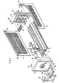
- the insert according to the invention for a system cabinet illustrated in FIG. 1 is essentially composed of a base part 10 designed as an extruded profile, a front wall 11, a rear wall 12 and finally lateral covers 13 and 14. Both the front wall 11 and the rear wall 12 provide Plastic molded parts, but they can also be formed as metallic injection molded parts just as well, particularly as far as the front wall is concerned.
- the front wall 11 is assigned a push-in handle 15 with a plate 17 which can be locked therein in a recess 16. Both the insertion handle 15 and the front wall 11 are fastened to the base part 10 by means of fastening screws 18 and 19, specifically by screwing these fastening screws 18 and 19 into correspondingly shaped channels 20 and 21 on the bottom part 10 designed as an extruded profile.
- a locking mechanism 28 which can be inserted into the base part 10 from the front, is illustrated for a circuit breaker or load switch with an associated actuating knob 29. It can be seen that the front wall 11 is provided for receiving the locking mechanism 28 with a special opening 30 through which an actuation axis 31 of the locking mechanism 28 can protrude. Further details are not of interest here, it should only be mentioned that front walls 11 with a different design of receiving elements for electrical functional elements can be used for accommodating other electrical functional elements or different types of switches or locking mechanisms.
- the rear wall 12 can also be used to hold electrical functional elements or connecting terminals and the like, for example a multipole plug element 32 or a package of several single-pole plug elements.
- the rear wall 12 is provided with a number of through openings which serve for the passage of power inlets and outlets - preferably also in the form of pluggable members; One of these through-openings has been provided with the number 33, representative of all other recognizable through-openings.
- this plug-in unit according to the invention can be accomplished very simply and quickly, because it only requires screwing in the four fastening screws 18, 19, 22 and 23 mentioned and then inserting and latching the side covers 13 and 14. Accordingly, it is also easy to carry out a loosening of one of the wall parts, which may be necessary for easier fitting or wiring of the interior of the insert.
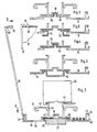
- FIG. 2 illustrates an end view of the base part 10, which is designed as an extruded profile, and the side cover 13 in its position, which has already been inserted into the base part 10 but has not yet engaged.
- the outwardly directed bottom surface 35 has an approximately C-shaped indentation 36 for receiving a support rail 37 located in the system cabinet.
- this C- shaped indentation 36 - in the middle leg 38 - an additional guide groove 39 is formed, the task of which will be explained below.
- channels 41 with approximately circular channel openings separated in a small circumferential area, which accommodate screws for fastening both the front wall and - on the opposite, not visible End of the bottom part 10 ⁇ serve the back wall.
- These channels 41 are located at the end of webs 42 which extend approximately parallel to the base surface 35 and which in turn originate from profile webs 43 which are located above the middle leg 38 of the C-shaped indentation 36 on the bottom.
- the profile webs 43 also have profile grooves 44, which can serve to accommodate (not indicated) electrical functional elements or an intermediate wall to be inserted (such is also not shown).
- the profiled bars 43 have at their free ends 45 directed towards each other in the insertion, which together form a snap-on system in the manner of a standardized top-hat rail and electrical functional elements (such is indicated with its outlines and has been identified with the number 46). to take up.
- the prerequisite is of course that the electrical functional elements are set up for a corresponding snap fastening on top hat rails.
- the lateral C-shaped projections 40 serve to receive the lateral covers, of which the one on the left (in the illustration) is also shown. It should be pointed out that the profile angles 47 of the side C-shaped projections 40 of the base part 10, which are more distant from the base surface 35, spring back by an amount corresponding to the thickness of the side covers 13 in relation to the free profile legs 48 directed towards them.
- the side covers 13 in their inserted position do not protrude beyond the outer boundary of the base part 10, at least not if they are provided with an offset 49 on their (in the illustration) lower wall area.
- this offset is designed so that here forms a narrow surface perpendicular to the plane of extent of the cover 13, which in the mounted position of the side cover 13 fits snugly against the end face of the adjacent profile leg 47, so that the cover 13 does not come in can slide up in the vertical direction.
- stiffening bends 50 can be seen and at the longitudinal ends additionally resilient locking hooks 51 are provided. These latching hooks 51 interact with the recesses 24 to 27 already shown in FIG.
- FIGS. 3 to 6 illustrate other advantageous training options for such support and guide rails, in which the base part 10, which has already been explained in detail, has been applied to different support rails.
- FIG. 3 is a top-hat rail 52, the U-shaped area of which is facing away from the bottom surface 35 of the bottom part 10.
- FIG. 4 also illustrates a top-hat-shaped mounting rail 53, the U-shaped area of which, however, is located opposite the mounting rail 52 mentioned above, namely the U-shaped area of this mounting rail 53 projects into the guide groove 39 already mentioned above.
- a pair of support rails 54 with a U-shaped profile are used, the free legs of these support rails 54 being directed towards one another and one of their legs projecting into the enclosed areas of the C-shaped indentation 36.
- a pair of mounting rails 55 is also used in FIG. 6, but here in the form of unequal-leg angle rails. The short legs protrude into the guide groove 39 already mentioned, while the long legs essentially fill the C-shaped indentation 36.
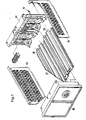
- FIG. 7 shows an insert which is doubled in its width compared to the insert shown in FIG. 1, in which the base part 57 is composed of two extruded profile parts 58 and 59 of the same length as those shown in FIGS. 1 and 2 is.
- These extruded profiles 58 and 59 which, incidentally, may or may not be connected to one another, are now each with a correspondingly wide front wall 60 and a rear wall 61 connectable, in the same way (that is, by means of corresponding screws 62) as is the case with the narrow insert explained above.
- Lateral covers 63 and 64 can now be added to a slide-in unit assembled in this way, as already described, which can be completely identical to those for narrow slide-in units according to FIG. 1. No further explanations are needed for this presentation.
Landscapes
- Engineering & Computer Science (AREA)
- Microelectronics & Electronic Packaging (AREA)
- Casings For Electric Apparatus (AREA)
- Table Devices Or Equipment (AREA)
- Brushes (AREA)
- Drawers Of Furniture (AREA)
- Gas-Insulated Switchgears (AREA)
- Packages (AREA)
- Patch Boards (AREA)
- Connection Or Junction Boxes (AREA)
Claims (16)
Priority Applications (1)
| Application Number | Priority Date | Filing Date | Title |
|---|---|---|---|
| AT83110507T ATE29642T1 (de) | 1982-11-22 | 1983-10-21 | Einschub fuer einen elektrischen anlagenschrank. |
Applications Claiming Priority (2)
| Application Number | Priority Date | Filing Date | Title |
|---|---|---|---|
| DE3243130 | 1982-11-22 | ||
| DE19823243130 DE3243130A1 (de) | 1982-11-22 | 1982-11-22 | Einschub fuer einen elektrischen anlagenschrank |
Publications (3)
| Publication Number | Publication Date |
|---|---|
| EP0109569A2 EP0109569A2 (fr) | 1984-05-30 |
| EP0109569A3 EP0109569A3 (en) | 1985-12-11 |
| EP0109569B1 true EP0109569B1 (fr) | 1987-09-09 |
Family
ID=6178702
Family Applications (1)
| Application Number | Title | Priority Date | Filing Date |
|---|---|---|---|
| EP83110507A Expired EP0109569B1 (fr) | 1982-11-22 | 1983-10-21 | Tiroir pour armoire destinée à des systèmes électriques |
Country Status (5)
| Country | Link |
|---|---|
| EP (1) | EP0109569B1 (fr) |
| AT (1) | ATE29642T1 (fr) |
| DE (2) | DE3243130A1 (fr) |
| NO (1) | NO161240C (fr) |
| YU (1) | YU228983A (fr) |
Cited By (2)
| Publication number | Priority date | Publication date | Assignee | Title |
|---|---|---|---|---|
| DE102010015576A1 (de) * | 2010-04-19 | 2011-10-20 | Abb Ag | Elektrisches Schaltgerät |
| CN105188285A (zh) * | 2015-09-29 | 2015-12-23 | 宁波一舟精密机械制造有限公司 | 机房机柜 |
Families Citing this family (8)
| Publication number | Priority date | Publication date | Assignee | Title |
|---|---|---|---|---|
| EP0171463B1 (fr) * | 1984-08-14 | 1990-06-27 | Rudolf Reinhardt | Réceptacle pour module électrique |
| EP0270844B1 (fr) * | 1986-11-18 | 1990-09-05 | Siemens Aktiengesellschaft | Boîtier, plus particulièrement un ensemble enfichable pour loger des cartes de circuits |
| DE4232918C2 (de) * | 1992-09-28 | 1995-02-16 | Siemens Ag | Einschiebbare elektrische Geräteeinheit |
| DE19511329A1 (de) * | 1995-03-28 | 1996-10-02 | Abb Patent Gmbh | Baugruppen-Befestigungssystem |
| DE19860380A1 (de) * | 1998-12-28 | 2000-06-29 | Julius Birkhold Gmbh | Fahrradstützvorrichtung eines Fahrradständers |
| ES2237300B1 (es) * | 2003-07-30 | 2006-03-16 | Hispano Mecano Electrica, S.A. | Perfil para fijar porta-regletas de telefonia y similares. |
| DE20312904U1 (de) | 2003-08-21 | 2003-11-20 | ABB Patent GmbH, 68526 Ladenburg | Vorrichtung zum Umlenken einer Drehbewegung in eine Kippbewegung |
| DE102005016543A1 (de) * | 2005-04-08 | 2006-10-12 | Abb Patent Gmbh | Elektrische Schaltanlage und Basismodul für eine elektrische Schaltanlage |
Family Cites Families (6)
| Publication number | Priority date | Publication date | Assignee | Title |
|---|---|---|---|---|
| CH526899A (de) * | 1969-08-26 | 1972-08-15 | Josef Mayr Franz | Gehäuse, insbesondere für elektronische Geräte |
| DE2316056A1 (de) * | 1973-03-30 | 1974-10-10 | Siemens Ag | In eine gestellaufnahme einsetzbare einschuebe |
| DE2515163C3 (de) * | 1975-04-08 | 1982-12-02 | Brown, Boveri & Cie Ag, 6800 Mannheim | Mehrzweckprofilschiene |
| DE2515152B2 (de) * | 1975-04-08 | 1980-04-10 | Brown, Boveri & Cie Ag, 6800 Mannheim | Elektrische Schaltanlage für Niederspannung |
| DE2946114A1 (de) * | 1979-11-15 | 1981-05-21 | Brown, Boveri & Cie Ag, 6800 Mannheim | Gehaeuse fuer elektrische bauteile |
| FR2491284A1 (fr) * | 1980-10-01 | 1982-04-02 | Trt Telecom Radio Electr | Coffret pour materiels electroniques et pieces de liaison destinees a de tels coffrets |
-
1982
- 1982-11-22 DE DE19823243130 patent/DE3243130A1/de active Granted
-
1983
- 1983-10-21 EP EP83110507A patent/EP0109569B1/fr not_active Expired
- 1983-10-21 AT AT83110507T patent/ATE29642T1/de not_active IP Right Cessation
- 1983-10-21 DE DE8383110507T patent/DE3373608D1/de not_active Expired
- 1983-11-21 NO NO834262A patent/NO161240C/no unknown
- 1983-11-22 YU YU02289/83A patent/YU228983A/xx unknown
Cited By (4)
| Publication number | Priority date | Publication date | Assignee | Title |
|---|---|---|---|---|
| DE102010015576A1 (de) * | 2010-04-19 | 2011-10-20 | Abb Ag | Elektrisches Schaltgerät |
| DE102010015576B4 (de) * | 2010-04-19 | 2014-07-10 | Abb Ag | Elektrisches Schaltgerät |
| CN105188285A (zh) * | 2015-09-29 | 2015-12-23 | 宁波一舟精密机械制造有限公司 | 机房机柜 |
| CN105188285B (zh) * | 2015-09-29 | 2018-07-06 | 宁波一舟精密机械制造有限公司 | 机房机柜 |
Also Published As
| Publication number | Publication date |
|---|---|
| ATE29642T1 (de) | 1987-09-15 |
| DE3243130A1 (de) | 1984-05-24 |
| NO161240B (no) | 1989-04-10 |
| YU228983A (en) | 1986-02-28 |
| NO161240C (no) | 1989-07-19 |
| DE3373608D1 (en) | 1987-10-15 |
| EP0109569A2 (fr) | 1984-05-30 |
| NO834262L (no) | 1984-05-23 |
| EP0109569A3 (en) | 1985-12-11 |
| DE3243130C2 (fr) | 1988-09-01 |
Similar Documents
| Publication | Publication Date | Title |
|---|---|---|
| EP1002351B1 (fr) | Baie comportant plusieurs plans de montage | |
| EP0872000B1 (fr) | Jeu de barres omnibus pour installation de commutation basse tension | |
| EP3446381A1 (fr) | Agencement permettant la connexion sans risque de contact d'un système de rails collecteurs de courant | |
| EP0109569B1 (fr) | Tiroir pour armoire destinée à des systèmes électriques | |
| DE19817919A1 (de) | Rahmenschenkel für ein Rahmengestell eines Schaltschrankes | |
| EP0702441B1 (fr) | Appareillage d'installation électrique, notamment pour canalisations de câbles | |
| EP1994614B1 (fr) | Construction a cadre pour une armoire electrique, armoire electrique et kit pour l'armoire electrique | |
| EP0109568B1 (fr) | Armoire ou châssis destiné à supporter des tiroirs pour systèmes électriques | |
| EP0872001B1 (fr) | Element enfichable pour installation de commutation basse tension | |
| WO1993020605A1 (fr) | Installation de distribution basse tension visant a fournir ou a distribuer de l'energie electrique | |
| EP1430579A1 (fr) | Socle pour un coffret de distribution | |
| EP1137137A1 (fr) | Adaptateur pour une armoire électrique | |
| DE19713948C2 (de) | Innenausbau für Schaltschränke | |
| DE2515164A1 (de) | Elektrische schaltanlage fuer niederspannung | |
| DE29704305U1 (de) | Geräteschrank | |
| DE2630280A1 (de) | Schaltgeruest | |
| DE4409024C1 (de) | Träger für einschiebbare elektrische Baugruppen | |
| EP1137135A1 (fr) | Système de barres omnibus pour une armoire électrique | |
| DE102006031763A1 (de) | Stromschienenhalter und Stromverteilereinheit mit einem Stromschienenhalter | |
| DE29706565U1 (de) | Schaltschrank für elektrische Anlagen | |
| DE69302358T2 (de) | Tragvorrichtung für modulare, elektrische Geräte | |
| CH646818A5 (en) | Switch cabinet, especially for an electrical low-voltage switching installation | |
| DE9204391U1 (de) | Einschub-Niederspannungsschaltanlage zur Abgabe oder Verteilung elektrischer Energie | |
| DE2734021C2 (de) | Schaltgerüst | |
| EP1137136A1 (fr) | Système de montage pour une armoire électrique |
Legal Events
| Date | Code | Title | Description |
|---|---|---|---|
| PUAI | Public reference made under article 153(3) epc to a published international application that has entered the european phase |
Free format text: ORIGINAL CODE: 0009012 |
|
| AK | Designated contracting states |
Designated state(s): AT BE CH DE GB LI NL SE |
|
| PUAL | Search report despatched |
Free format text: ORIGINAL CODE: 0009013 |
|
| AK | Designated contracting states |
Designated state(s): AT BE CH DE GB LI NL SE |
|
| 17P | Request for examination filed |
Effective date: 19851125 |
|
| 17Q | First examination report despatched |
Effective date: 19861118 |
|
| GRAA | (expected) grant |
Free format text: ORIGINAL CODE: 0009210 |
|
| AK | Designated contracting states |
Kind code of ref document: B1 Designated state(s): AT BE CH DE GB LI NL SE |
|
| REF | Corresponds to: |
Ref document number: 29642 Country of ref document: AT Date of ref document: 19870915 Kind code of ref document: T |
|
| REF | Corresponds to: |
Ref document number: 3373608 Country of ref document: DE Date of ref document: 19871015 |
|
| GBT | Gb: translation of ep patent filed (gb section 77(6)(a)/1977) | ||
| BECN | Be: change of holder's name |
Effective date: 19870909 |
|
| RAP2 | Party data changed (patent owner data changed or rights of a patent transferred) |
Owner name: BBC BROWN BOVERI AG |
|
| NLT2 | Nl: modifications (of names), taken from the european patent patent bulletin |
Owner name: BBC BROWN BOVERI AG TE BADEN, ZWITSERLAND. |
|
| PLBE | No opposition filed within time limit |
Free format text: ORIGINAL CODE: 0009261 |
|
| STAA | Information on the status of an ep patent application or granted ep patent |
Free format text: STATUS: NO OPPOSITION FILED WITHIN TIME LIMIT |
|
| 26N | No opposition filed | ||
| PGFP | Annual fee paid to national office [announced via postgrant information from national office to epo] |
Ref country code: GB Payment date: 19940822 Year of fee payment: 12 |
|
| PGFP | Annual fee paid to national office [announced via postgrant information from national office to epo] |
Ref country code: AT Payment date: 19940919 Year of fee payment: 12 |
|
| PGFP | Annual fee paid to national office [announced via postgrant information from national office to epo] |
Ref country code: BE Payment date: 19940928 Year of fee payment: 12 |
|
| PGFP | Annual fee paid to national office [announced via postgrant information from national office to epo] |
Ref country code: NL Payment date: 19941031 Year of fee payment: 12 |
|
| EAL | Se: european patent in force in sweden |
Ref document number: 83110507.7 |
|
| PG25 | Lapsed in a contracting state [announced via postgrant information from national office to epo] |
Ref country code: GB Effective date: 19951021 Ref country code: AT Effective date: 19951021 |
|
| PG25 | Lapsed in a contracting state [announced via postgrant information from national office to epo] |
Ref country code: BE Effective date: 19951031 |
|
| BERE | Be: lapsed |
Owner name: BBC BROWN BOVERI A.G. Effective date: 19951031 |
|
| PG25 | Lapsed in a contracting state [announced via postgrant information from national office to epo] |
Ref country code: NL Effective date: 19960501 |
|
| GBPC | Gb: european patent ceased through non-payment of renewal fee |
Effective date: 19951021 |
|
| NLV4 | Nl: lapsed or anulled due to non-payment of the annual fee |
Effective date: 19960501 |
|
| PGFP | Annual fee paid to national office [announced via postgrant information from national office to epo] |
Ref country code: SE Payment date: 19980629 Year of fee payment: 16 |
|
| PGFP | Annual fee paid to national office [announced via postgrant information from national office to epo] |
Ref country code: CH Payment date: 19980824 Year of fee payment: 16 |
|
| PG25 | Lapsed in a contracting state [announced via postgrant information from national office to epo] |
Ref country code: SE Free format text: THE PATENT HAS BEEN ANNULLED BY A DECISION OF A NATIONAL AUTHORITY Effective date: 19991030 |
|
| PG25 | Lapsed in a contracting state [announced via postgrant information from national office to epo] |
Ref country code: LI Free format text: LAPSE BECAUSE OF NON-PAYMENT OF DUE FEES Effective date: 19991031 Ref country code: CH Free format text: LAPSE BECAUSE OF NON-PAYMENT OF DUE FEES Effective date: 19991031 |
|
| REG | Reference to a national code |
Ref country code: CH Ref legal event code: PL |
|
| EUG | Se: european patent has lapsed |
Ref document number: 83110507.7 |
|
| PGFP | Annual fee paid to national office [announced via postgrant information from national office to epo] |
Ref country code: DE Payment date: 20020903 Year of fee payment: 20 |