EP0109593B1 - Récipient avec fermeture comprenant des moyens pour indiquer l'ouverture non-autorisée - Google Patents
Récipient avec fermeture comprenant des moyens pour indiquer l'ouverture non-autorisée Download PDFInfo
- Publication number
- EP0109593B1 EP0109593B1 EP83111026A EP83111026A EP0109593B1 EP 0109593 B1 EP0109593 B1 EP 0109593B1 EP 83111026 A EP83111026 A EP 83111026A EP 83111026 A EP83111026 A EP 83111026A EP 0109593 B1 EP0109593 B1 EP 0109593B1
- Authority
- EP
- European Patent Office
- Prior art keywords
- tamper
- container
- closure
- indicating element
- layer
- Prior art date
- Legal status (The legal status is an assumption and is not a legal conclusion. Google has not performed a legal analysis and makes no representation as to the accuracy of the status listed.)
- Expired
Links
Images


Classifications
-
- B—PERFORMING OPERATIONS; TRANSPORTING
- B65—CONVEYING; PACKING; STORING; HANDLING THIN OR FILAMENTARY MATERIAL
- B65D—CONTAINERS FOR STORAGE OR TRANSPORT OF ARTICLES OR MATERIALS, e.g. BAGS, BARRELS, BOTTLES, BOXES, CANS, CARTONS, CRATES, DRUMS, JARS, TANKS, HOPPERS, FORWARDING CONTAINERS; ACCESSORIES, CLOSURES, OR FITTINGS THEREFOR; PACKAGING ELEMENTS; PACKAGES
- B65D55/00—Accessories for container closures not otherwise provided for
- B65D55/02—Locking devices; Means for discouraging or indicating unauthorised opening or removal of closure
- B65D55/06—Deformable or tearable wires, strings or strips; Use of seals
- B65D55/066—Foil covers combined with outer closures and comprising interacting or interposed tamper indicating means visible through the outer closure, e.g. releasable coloured dyes, changeable patterns, pierceable membranes, visible through a transparent closure or through a window
Definitions
- This invention relates generally to container closures of tamper-indicating type and containers provided with such closures.
- US-A-2 939 597 there is described a container closure for providing tamper-indication.
- This closure has a closure member defining a container closure expanse and adapted for rotative first and second movements for closing and opening the container with at least one protrusion depending from the top of the closure member for engagement with a tamper-indicating element and radially offset from the rotation center of the first and second movements.
- the tamper-indicating element of this container closure is retained within the closure member and at least one protrusion is inaccessible through the closing expanse and said closure affording visibility therethrough of the tamper-indicating element which has a higher frictional adherence to the container than to the closure member.
- the cooperating parts such as the protrusions and ratchet teeth, move relatively into a position in which the closure member has been advanced a part of the turn while a locking member remains stationary. Therefore the previously hidden printed indication of the tamper-indicating element will become visible. As the locking member cannot be removed from the closure member the tamper-indicating element will remain in such a position that the printed indication is visible even if the closure member is applied again to reseal the container.
- This known tamper-indicating element uses a printed indication in order to indicate that the closure member has already been opened.
- teltale indication i.e., a tamper-indicating means or a readily discernible characteristic indicative of tampering, such as a signal that some person has previously attempted to gain access to the container contents.
- this approach can be generalized as placing a tamper-indicating member in the path of access to a container to indicate tampering by discernible change.
- tamper-indicating means one finds in the prior art approaches elements which evidence color change, which mechanically present literal messages, and which are ruptured or torn upon the occurrence of tampering.
- the color change devices may be considered less than desirable as requiring ambient-sensitive constituents and measures for sealing same from ambient environment.
- the mechanical devices providing literal indication i.e., the words "closed” or “open” (see for example US-A-2 939 597), are less than desirable as they are inherently complex and customized.
- the rupturing and tearing practice offers the best potential for desired simplicity in solution.
- Prior art tamper-indicating means may also be categorized in respect of the relative location thereof to the container access port.
- the tamper-indicating means are located directly at the access port and wherein the tamper-indicating means are otherwise located in the path of access to the container.
- tamper-indicating means directly span the access opening, e.g., are secured across the mouths of jars.
- the tamper-indicating means are located in container wrappers, within plastic heat shrunk about the capped jar, etc.
- the effective location for a tamper indicator is directly at the access port, since wrappers, heat shrunk plastic sleeves and like tamper-indicating means outside the container may be removed and the remaining capped container remain without tamper indication.
- prior art tamper indication may be categorized as of type wherein the tamper-indicating means directly at the access opening is closure member activated or not.
- the former category reverse sense (opening) movement of the closure member or closure cap brings some element into tearing relation with the tamper-indicating means.
- tamper-indicating means is unaffected by closure member removal.
- closure member activated case affords greater security.
- US-A-2,131,774 and US-A-2,131,775 are considered to disclose tamper-indicating containers incorporating the desired of the foregoing categories of tamper indication.
- the tamper-indicating element is simple rupturable sheet material. The element is located directly at the container mouth opening and is cap-activated. In accommodating this operative selection of features, however, these disclosed tamper-indicating containers have vulnerability, recognized expressly in the patents, to direct tampering with the tamper-indicating element.
- the Waring US-A-2 131774 practice is to provide a cap in the form of a hollow cylinder having a skirt depending from the cap top and interiorly threaded to receive the jar neck.
- the cap top is centrally open and prongs are formed in the plane of the cap extending into the central opening.
- the tamper-indicating element is nested in the cap interior and suitably secured therein.
- the cap with its nested tamper-indicating element is then rotated into secured relation with the jar. Now the prongs are bent out of the plane of the cap top and into puncturing relation with the tamper-indicating element, remaining accessible through the open cap top.
- the tamper-indicating element is secured to the cap for movement therewith, the cap again having its top centrally open.
- a liner is stapled, stitched or glued to the tamper-indicating element.
- a frictional undersurface of the liner is compressed onto the jar neck by friction therebetween.
- the cap and tamper-indicating element rotate initially relative to the liner and staple, whereby the staple ruptures the tamper-indicating element.
- the limitation of the US-A-2 131 774 practice is again present, i.e., the staple is accessible at all times through the open cap center.
- cap liners with the cap during cap shipment and cap application to containers is a present industry practice, as is shown, for example, in US-A-3,819,460 and 3,917,100.
- a circumferential groove is formed in the cap immediately beneath the cap top panel above the cap threads.
- the liner is forced into the cap and nests in the retention groove.
- the liner includes a compressible layer which is said to be displaced radially outwardly of the liner into sealing relation with the groove wall as the cap is threaded upon a container.
- tamper indication is not involved and there is no anchoring of the liners to the container mouth, as by adhesive or other bond.
- This invention has as its primary object the provision of improved tamper indication for containers of the capped type.
- the invention has as a further object the accommodation of the above-noted practice selections and existing practices in the related industries.
- the present invention has as another object the provision of tamper indication systems wherein the alternative user preference is accommodated in both of its requirements.
- a container closure for providing tamper indication having a closure member defining a container closure expanse and adapted for rotative first and second movements for closing and opening the container with at least one protrusion depending from the top of the closure member for engagement with a tamper-indicating element and radially offset from the rotation center of such first and second movement; said tamper-indicating element being retained within the closure member, said at least one protrusion being inaccessible through said closing expanse and said closure affording visibility therethrough of the tamper-indicating element which has a higher frictionat adherence to the container than to the closure member (as known from US-A-2,939,597), whereby the container closure is characterized in that at least one protrusion is designed for selectively tearing said tamper-indicating element during said second movement.
- the tamper-indicating element may be in the form of a simple paper seal closing the mouth, and the closure may be a see-through cap releasably securable to the container and circumscribing its mouth and the tamper-indicating element when secured to the container.
- the cap includes one or more puncturing elements in form of protrusions interiorly of the cap for travel with the cap.
- the tamper-indicating element is arranged in captive relation to the puncturing element prior to assembly of the cap with the container. As the cap is rotated in securement with the container, the tamper-indicating element becomes secured to the container mouth as it engages same, for example, through contact activation of a sealant on the container or jar mouth. Reverse sense opening movement of the cap is accompanied by visible rupturing and tearing of the tamper-indicating element.
- the puncturing element may take the form of one or more knife-like tines depending from the cap upper interior surface and non- deflectable relative thereto.
- the cap is made of transparent material such that the condition of the tamper-indicating element may be viewed constantly after the initial assembly juncture and to the point of consumer sale.
- the cap tines have a tamper-indicating wafer applied thereto and the tines are then blunted upon the tamper-indicating wafer undersurface.
- a second wafer is now adhesively secured to the tamper-indicating wafer and, since the second wafer is unaffected by the tines when the tamper-indicating wafer is ruptured, the second wafer can maintain the jar sealed and its contents unaffected by tamper-indicating wafer ruptured parts.
- a further tamper-indicating element has a compressible layer, such as foam, in which the tines are captive.
- the preferred tamper-indicating element is a laminate inclusive of such compressible layer and an underlayer which is both effective to blunt the tines in fully captured relation in the compressible layer and to serve as a jar sealing layer.
- a foil overlayer may also be included.
- the cap may include means for distributing force applied to the tamper-indicating element to its periphery, thereby lessening the likelihood of tine rupture of the tamper-indicating element in movement of the cap into initial securement with a jar.
- the force distributing means may also serve as a cap reseal for a jar upon removal of the tamper-indicating element after initial jar opening.
- the invention further encompasses an overcap for the closure cap to defeat malicious activations of the tamper-indication element.
- a further embodiment of the invention includes, in addition to the tines, means within the cap for engaging the tamper-indicating element selectively subsequent to its activation on cap opening movement, both to forcibly break the sealing bond between the tamper-indicating laminate and container and to retain the tamper-indicating laminate with the cap.
- the tamper-indicating laminate is secured to the container mouth, as by induction heating, and the tamper-indicating laminate is so structured as to maintain its integrity as it is forcibly separated from such securement in the course of cap opening movement.
- the invention provides a container in the form of a vessel comprising the customary neck terminating in a container mouth and defining surface extent circumscribing the mouth and inclusive of container sealing surface and the neck has the typical threads for closure member securing thereon.
- the container surface extent is adapted for engaging the tamper-indicating element and is configured to effect first and second different engagements therewith respectively in the course of the first and second sense movements.
- the container permits the tamper-indicating element to be moved into closure relation with the sealing surface in first sense closure movement and to be selectively positively restrained from movement relative to the mouth in the initial phase of the second sense closure member movement without need for an adhesive layer or other bonding agent between the container neck and the tamper-indicating element.
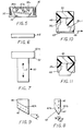
- closure or cap 10 includes a closure member 12 having depending skirt 12a and interior threading 14 with lower opening 16.
- the cap defines closing expanse comprising skirt 12a and the undersurface 12b of cap 10, for registry with the neck and mouth of a jar or like container having an access opening for obtaining its contents.
- cap 10 Interiorly of such closing expanse, cap 10 includes one or more tines, three being shown as 18a, 18b and 18c, comprising puncturing and tearing or rupturing elements spaced at equal angles.
- Each tine may be formed integrally with cap 10, e.g., is molded therewith, and is rigid, such that it is not readily deflectable relative to cap undersurface 12b.
- the tines may be parts of an insert to cap 10, which is secured therein for movement therewith. Based upon its secured relation to cap 10, each tine travels with the cap in the course of its first sense (clockwise) movement into releasably secured relation with the jar neck and also in the course of second opposite sense (counterclockwise) cap movement relative to the jar for release from such secured relation therewith.
- Cap 10 is formed of optically clear plastics of butyrate, acetate, nylon, lucite and plexiglass and the like.
- the jar for use with cap 10 is preferably made of glasser thermoplastics such as will provide a barrier to covert penetration, such as by use of a hypodermic needle. High impact styrene is suitable.
- tine 18c shown in Figs. 3 and 4
- same includes a vertically extending radially outward wall 20, terminating in inverse V-shaped groove or rupturing channel 22, bounded by surfaces 24a and 24b, each forming angle A (forty-five degrees) with the central vertical plane of tine (axis 26 on Figure 3).
- the channel extends radially inwardly and upwardly to interior wall 28 at angle B (thirty degrees).
- cap 30 has skirt 32, interior threading 34, interior cap undersurface 30a and supports tines 36a, 36b and 36c, extending in the direction of lower opening 38.
- each of tines 18a-c and 36a-c is radially offset from the center of the rotative movements of caps 10 and 30 and that each extends generally parallel to the axis of the hollow cylindrical cap.
- Each tine is also disposed radially of the rotation center, thus having extent generally radial to provide a frontal expanse for rupturing or tearing of a member penetrated thereby.
- tines 36a-c will be seen to involve an asymmetry about axis 40.
- V-shaped configuration is defined by tapered sidewalls 42 and 44, the former starting its taper at location 42a, higher than that 44a for the latter. Both taper at angle C (thirty degrees) and incline radially inwardly upwardly from outward wall 45 to interior wall 46 at angle D (thirty degrees).
- the asymmetry gives rise to a preferential directional deformation oftines as indicated for tine 36c in Fig. 10 upon assembly as now discussed.
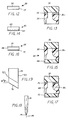
- tamper indication means 48 is a generally flat disk which may be comprised of a layer of foam alone, e.g., styrene based plastic foam.
- Assembly tool 50 (Fig. 7) includes a backing member 52, being rigid in practice under present discussion, e.g., a metal cylinder, for receiving layer means 48 on its upper surface 52a and is movable in direction E for inserting layer means 48 into opening 38 of cap 30.
- Fig. 10 shows the assembly resulting from such insertion practice with a rigid backing member.
- the entirety of tine 36c is situated in layer means 48, with end portion 36c-1 of the tine positioned in spaced relation to layer means undersurface and with thetine defining a generally hooked shape at its end portion 36c-1, such hook being in retentive relation to layer means 48 and extending in direction F, i.e., the direction of opening movement (counterclockwise rotation) of cap 30.
- the tine is disposed to enhance tearing of layer means 48 in the course of opening movement of cap 30 and accordingly is adapted to heighten tamper indication.
- tine 36c is so deformed that reuse of the cap by a would-be tamperer is negated.
- Layer means 48 may carry on its undersurface a marginal ring 53 of contact-activated adhesive, or same may be applied to the jar mouth, whereby the Fig. 10 assembly has jar securement. With tine 36c spaced from such undersurface, ruptured fragments of layer means 48 may be removed upon container opening without entering the container.
- Backing member 52 may, if desired, be a compressible member, e.g., rubber, to reach the assembly shown in Fig. 11.
- a major extent of tine 36c is situated in layer means 48 (more than half of its vertical extent), thus enhancing tamper-indicating element rupture. Retention is effected by the remnant of tine 36c exteriorly situated with respect to layer means 48.
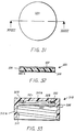
- the tamper indication means 48 has been discussed as constituted by foam for layer means 48, the invention contemplates various other tamper-indication means, some of which are seen in Figs. 12, 14 and 16.
- the tamper-indication means comprises foam layer 54 in assembly with overlayer 56 of metal foil, defining laminate 58.
- Practice of the Fig. 10 method i.e., rigid backing member, gives rise to the assembly of Fig. 13, wherein tine 36c penetrates and is thus situated in both layers of the laminate.
- the laminate 60 comprises foam layer 62 and underlayer 64 constituting a container access port seal, e.g., glassine or like sealing layer.
- a container access port seal e.g., glassine or like sealing layer.
- the laminate 66 comprises foam layer 68 together with metal foil layer 70 intervening in between layer 68 and cap undersurface 30a and secured to one surface of layer 68, and with underlying glassine layer 72 secured to the side of layer 68 opposite such one surface thereof.
- tine 36c penetrates the metal foil layer 70 and foam layer 68 and is spacedly disposed relative to the glassine underlayer 72, which is securable to the jar mouth as above discussed.
- Tines may take the further configuration shown in Figs. 18 and 19.
- tine 74 is symmetrical about axis 76 and defines piercing apex 78 inclined radially inwardly upwardly between end walls 80 and 82.
- the upper surfaces of container access port sealing layers of glassine or like dense paper are provided with coloration, e.g., bright red, and the foam layers are of offset color, e.g., white, whereby a vivid tamper indication is provided as the closure member is rotated in the opening direction.
- coloration e.g., bright red
- foam layers are of offset color, e.g., white
- surety of tamper indication is effected.
- the securement aspect whereby an interior glassine wafer is captured in a closure member through its adhesion to the captured foam gives the described methods utility in non-tamper indication applications, i.e., where it is desired to avoid customary release of container access port sealing layers from caps in shipment and handling.
- closure 110 includes cap 112, preferably having vertical groupings of ribs 114 mutually spaced about the exterior of the depending skirt of the cap.
- Cap 112 has interior threads 116 for securement to a container and includes tines 118 extending downwardly from the cap upper interior surface within the cap container closing expanse.
- a tamper indication means 120 which may be paper sheet material, is secured to tines 118, which pierce through the tamper-indication means as it is forced thereover into the cap interior.
- Tines 118 are movable with cap 112, preferably being formed integrally therewith, and tamper-indication means 120 is movable by the tines with the cap as the cap is secured to a container.
- the cap is of see-through character, being of suitable translucent plastic or the like, such that the state of tamper-indication means 120 is visible through the cap.
- closure 122 includes the foregoing structure in common with closure 110, and further has an access port sealing layer 124 secured at its periphery to tamper-indication means 120 after tines 118 are rolled over as indicated.
- the tine rollover or staking step has benefit in enhancing the tearing thereof. Further, the step places the preassembly attained thereby in such posture that it may now receive an underlayer, as part of the cap as manufactured, having its integrity unaffected by activation of the tamper-indication means. Thus, with the tine ends now blunted and not having their prior puncturing and tearing capability below the tamper-indication means, jar mouth or container access port sealing layer 124 is isolated from the tines. Referring to Fig.
- an adhesive 126 may be applied either to the mouth of container 128 or to the undersurface of layer 124, such that, upon securement of closure 122 to the jar by engagement of cap threads 116 with container neck threads 130, layer 124 becomes secured to the container and hence teltale 120 is rendered fixed relative to the container. Gripping of closure 122 and counterclockwise rotation thereof effects a tearing of teltale 120 and indicates initial opening of the container.
- tamper sentry 132 is in the form of an overcap 134, having a central opening 136 through its upper surface, depending skirt 138, generally horizontal endless ribs 140 and 142 and latch 144 adjacent opening 146.
- the overcap is so dimensioned as to be assembled with cap 112 as shown in Figs. 24 and 25, i.e., to vertically non-frictionally nest cap 112 therein and to latchingly retain same through latch 144, which extends radially interiorly of the periphery of cap 112.
- Ribs 140 and 142 engage only rib groupings 114 of cap 112, in the illustrated embodiment, as shown in the enlarged showing of Fig.
- overcap 134 substantially thwarting sufficient frictional interface between overcap 134 and tamper-indicating cap 122 for a human to rotate cap 122, absent prying off the overcap.
- the overcap is in secured circumscribing relation to the cap and is supported thereby for rotation. If the overcap is gripped by a would-be tamperer, there results a spinning thereof without movement of the cap and hence without activation of the tamper-indication means.
- opening 136 in the overcap also serves the purpose of enabling visualization of the state of the tamper-indicating element 120.
- the tamper-indicating element used in practicing the invention is in the configuration of a laminate or multilayer indicating-element, as in Figs. 12 and 16, i.e., including an upper foil member of highly tearable nature, or in the form of delicate sheet material, again quite readily tearable, practice as above discussed can present difficulty in assembly, particularly as the assembly of closure and tamper-indicating element is rotated into securement with a container.
- the tines are alone in force-imposing relation to the tamper-indicating element and alone carry it into desired position in the final assembly. In such cap closing sense movement, a point is reached at which the tamper-indicating element is compressed between the cap and container, and at that juncture, resistance to further rotation is met.
- cap 512 has formed integrally therein radially extending ribs 528, disposed outboard of tines 516 and at the interior periphery of cap 512.
- the ribs have generally vertical rises 528a at their cap clockwise sides, the rises extending downwardly from cap undersurface 512a, as is seen in Fig. 45 for the single such rib illustratively shown.
- the ribs have trailing ramps 528b at their cap counterclockwise sides.
- cap closing sense rotative movement is accompanied by forceful engagement of rib rises 528a with tamper-indicating element 520 at its upper surface along with the tines, effectively distributing the force applied to the tamper-indicating element and permitting use of delicate tamper-indicating elements, e.g., foils, thin paper and the like.
- ramps 528b ride over the tamper-indicating surface, and tearing is effected by the tines.
- closure 230 includes closure cap 232 and a force-imparting member 234 is secured in the cap interior, adjacent cap undersurface and is preferably in the form of a ring in circumscribing non-interfering relation to tines 216.
- Member 234 is selected to be of plastic composition which is more compressible than the plastic material constituting cap 232 and is also selected, relative to tamper-indicating element 220, to impart frictional force to the tamper-indicating upper surface upon compression of member 234 between cap 232 and tamper-indicating element 220.
- the tamper-indicating element is inserted in the cap to provide the assembly of Fig.
- Fig. 28 container upon initial opening of the Fig. 28 container, one may remove the torn tamper-indicating element from the closure and remove layer 226 from the container to gain access to the contents of the container, but may reseal the container by virtue of the remaining presence of member 234 in the closure and its characteristic compressibility adapted also for direct sealing engagement of undersurface 234a with the container adjacent its access port.
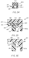
- closure 310 includes cap or closure member 312, having skirt 312a and interior threads 314 for securement to a container and including tines 316 (316a, 316b, 316c) extending downwardly from cap upper interior undersurface 312b of cap top panel 312c and disposed within the cap container closing expanse, comprised of such skirt and top panel.
- Tines 316a-c which may be one or more in number, are shown arranged as three puncturing elements spaced at equal angles.
- Tamper-indicating element 320 may be in configuration of a laminate or multilayer tamper-indicating element, including an upper foil member 322 of highly tearable nature, an intermediate layer 324 of foam or like compressible material and a lower layer 326 of dense paper, such as glassine.
- Tamper-indicating element 320 is assembled with cap 312 by inverting cap 312 from its Fig. 30 disposition, positioning tamper-indicating element 320 in registry with cap open end 312d, applying a rigid tool, e.g., a metal cylinder, to layer 326 and forcing tamper-indicating element 320 against cap top panel 312c.
- a rigid tool e.g., a metal cylinder
- tines 316 are distorted within foam layer 324, as shown in sectional view of Fig. 34, i.e., tine 316b is flattened against glassine layer into boot-like configuration 316b-1 in foam layer 324 and is in penetrating relation to both foil layer 322 and foam layer 324.
- Layer 326 may include a tamper-indicating indicium 326a e.g., a red coloration, on its surface juxtaposed with foam layer 324.
- the means of Figs. 29 and 30 for such tamper-indicating protecting purpose effects displacement of the tamper-indicating element into frictional engagement with the interior of the closure member skirt, which desirably has its surface confronting the displaced tamper-indicating element formed in such manner as to heighten such frictional engagement.
- the same structure can both fulfill a reseal function as heretofore known, and, in further heretofore unkown and unexpected function, realize a tamper-indicating element displacement and protection function, as is now discussed.
- force imparting means in the form of a flexible cone 328 is integral with, or is otherwise fixed within, cap 312.
- Cone 328 commences at one end portion 330 coter- minus with top panel 312c, at a location radially outward of the location of tines 316a-c, and extends in cantilevered manner to opposite end portion 332, which defines a flat horizontal surface 334, generally parallel to top panel 312c.
- the foregoing structure has use generally in container closing aspect as an anti-backoff closure.
- backoff is meant the undesirable self-loosening of a closure from securement with a container, such as happens with vibration in the course of shipment, with temperature change, etc.
- anti-backoff structure as is provided above, i.e., wherein (1) the closure member has a locked relation to the teltale, particularly by the tines and such described displacement of the tamper-indicating element into engagement peripherally with projections 336 by means 328 compression of foam layer 324, and (2) a second interlock exists as between the teltale and the container through adhesive 340.
- tamper-evident aspect could employ an opaque cap with tines or other means securing the cap with a substitute for tamper-indicating element 320, e.g., a compressible and outwardly displaceable member of non-tamper-indicating character.
- a substitute for tamper-indicating element 320 e.g., a compressible and outwardly displaceable member of non-tamper-indicating character.
- tamper-indicating element 320 may be secured to tines 316 by a container, as is now discussed.
- deflection of means 328 may occur in the course of securement of cap 312 with container 318.
- surface 338 of container 318 bounding its access port has adhesive 340 thereon and registers vertically with end portion 332 of means 328.
- means 328 is deflected toward top panel 312c. End portion 332 bites into foil layer 322 and compresses foam layer 324 which expands rightwardly of its compressed area, thereby displacing tamper-indicating element 320 outwardly into engagement with projections 336.
- tamper-indicating element 320 Upon initial opening of the Fig. 35 capped container, tamper-indicating element 320 is torn by tines 316, since tamper-indicating element 320 is secured by adhesive 340 to container 318. The tamper-indicating element is now removed from cap 312, i.e., by peeling same from tines 316.
- the tamper-indicating member-less cap is seen in Fig. 36, which also shows the reseal capability of tamper-indicating element protection means 328.
- flat surface 334 of end portion 332 is in sealed relation with surface 338 of container 318, desirably in flat horizontal disposition, generally parallel to top panel 312c, as indicated in Fig. 36.
- container 410 includes cap or closure member 412 of see-through plastic material having skirt 414 with interior threads 416.
- a circumferential bead 418 projects inwardly from skirt 414 with threads 416, but is fully horizontally disposed, and defines with undersurface 412a of the cap top 412b a recess or groove 420.
- Tines 422a, 422b and 422c (Fig. 5) are movable with cap 412 in its rotative movement.
- Each tine tapers to piercing apex as shown at 422a-1 and 422b-1 in Fig. 37 and is preferably of length below undersurface 418a less than the vertical run of recess 420.
- the preferred structure of tamper-indicating assembly 424 is a laminate, as is seen in the enlarged view of Fig. 40.
- the laminate includes an uppermost compressible layer 426 of material, e.g., open cell styrofoam, which is rupturable and tearable by tines 422a ⁇ 422c. This layer is desirably from 762 pm to 889 pm mils in thickness.
- a printed pattern is applied to top surface 426a of layer 426.
- a strip pattern adhesive 427 is applied to stiffening layer 428 for securement thereof to the undersurface of layer 426.
- This strip pattern adhesive layer is comprised of a pressure-sensitive hot melt, and may be about 25.4 pm in thickness.
- Assembly 424 is cylindrical or disk-shaped and the individual strips, one identified at 427a, of the pattern adhesive layer are spaced from other strips and extend chordally of the cylinder.
- Stiffening layer 428 is comprised of a clear K-resin and is preferably from 101.6 um to 254 pm.
- the above- mentioned pressure-sensitive adhesive bonds layer 428 to tamper-indicating layer 430, which is a paper of about 25.4 um in thickness.
- Bottom layer 432 is a 25.4 pm aluminum foil which is coated with general purpose polyethylene or Surlyn (trademark) etc. Color and pattern features are significant, both from a security and control viewpoint and tamper indication viewpoint.
- the printed pattern on surface 426a is desirably a thin line green imprinting to impart an anti-counterfeit character to tamper-indicating assembly 424.
- Layer 426 is preferably white foam and the coloration of tamper-indicating paper layer 430 is desirably red on its surface facing clear stiffening layer 428.
- jar 434 is partially shown and has neck 436 with exterior threads 438.
- a layer 440 of controlled release type adhesive may be applied to the mouth of neck 436.
- cap 412 is inverted from its Fig. 37 orientation and tamper-indicating assembly 424 is forced against surface 412a of top panel 412 by a rigid, e.g., metal, backing member applied to layer 432 of assembly 424.
- Layer 426 is punctured by the tines and the tines are deformed in the foam, effecting retention of assembly 424 by the tines.
- Fig. 38 wherein tamper-indicating assembly 424 is nested in recess 420 and is held by the tines in preselected spaced vertical relation to bead 418, for purposes below discussed.
- cap 412 is fully threaded in container closing sense (full clockwise movement as in Fig. 41).
- Layer 432 (Fig. 40) of tamper-indicating assembly 424 is secured to the mouth of neck 436 by adhesive layer 440 and the tamper-indicating assembly is thus anchored to both cap 412 and jar 434.
- layer 432 is polyethylene-coated aluminum, or other compatible coating as above discussed, the latter anchoring is done preferably by induction heating of the aluminum foil, which directly bonds the coating to the container neck, without need for a separate adhesive.
- a measure of counterclockwise (opening sense) rotation of cap 412 can occur prior to any confrontational engagement of bead 418 with layer 432 and hence prior to any discontinuance of the anchoring of assembly 424 to the mouth of neck 436.
- tines 422a, 422b and 422c tear through foam layer 426, giving rise to a revealing of tamper-indicating layer 430 in areas 442, 444 and 446 as shown in Fig. 42, and the presentation of the vivid red layer 430 through the white foam against the green line background atop foam layer 426.
- a tamper-indicating assembly design consideration which assists in the realization of the features discussed immediately above, is the character of layer 428 of tamper-indicating assembly 424.
- This layer is effective to withstand the camming force applied to the tamper-indicating assembly by bead 418 in the course of its release from jar 434, while at the same time retaining the cylindrical geometric configuration of assembly 424.
- assembly 424 will thus be seen to have an anti-counterfeit imprint atop a tine securement layer (layer 426), a layer for maintenance of structural integrity (layer 428), a tamper-indicating layer (layer430) and sealing and reseal layer (layer432).
- cap 412 will be seen to have plural and successively operative means for retention of tamper-indicating assembly 424.
- Tines 422a-422c represent first means for tamper-indicating assembly retention, being imbedded in layer 426 upon cap and tamper-indicating assembly. Bead 418 is inactive until such time as tines 422a-422c have ruptured layer 426 and lost retentive relation therewith, but follows tamper-indicating assembly 424 to retentively and con- tinuingly engage the same following tamper-indicating activation.
- the tamper-indicating means can be in the multilayer form shown as element 320 (Fig. 32) and in other tamper-indicating configuration, for example, running from a single paper layer disrupted by the tines to other multilayer structures, e.g., wherein a foam layer is in immediate juxtaposition to the cap top panel and is supported by an encapsulated aluminum layer, the latter being in present commercial usage. Where the foam layer is opaque, the aluminum layer, or other underlying tamper-indicating means is seen in its portions in registry with the translucent tines, when inactivated, and is highly visible upon activation.
- tamper-indicating structure could see an upper paper layer, a foam layer, a lower paper layer and a lowermost layer comprising Surlan (trademark) coated aluminum foil. While engagement of the tines and tamper-indicating structure has been shown as involving penetration of the tamper-indicating means by the tines, the invention contemplates also a surface joinder of the tines and tamper-indicating means, e.g., the tines having surface engaging the tamper-indicating upper surface and such surfaces being heat bonded together. Further, while the depicted embodiments employ rotative closures having internal threads, the invention requires only that the closures be rotative for tamper-indicating activation.
- tamper-indicating assembly 424 would be to form the tamper indication atop the stiffening layer, as by coloration on the upper surface thereof.
- the stiffening layer may now be constituted of opaque material, such as hardboard, since the tamper indication is not required to be seen therethrough as in the first discussed embodiment, wherein the stiffening layer of K-resin has see-through character.
- FIG. 46 through 48 another embodiment of the invention involves a tamper- indicative container having a vessel with facility for non-adhesive engagement with the container closure member.
- Vessel 610 includes a neck 612 bearing suitable cap securement threads 614 on its exterior surface and providing an access channel between the vessel mouth and vessel interior compartment 616.
- the vessel defines surface extent circumscribing the mouth, inclusive of peripheral teeth 618, a flat expanse 620 and vessel sealing surface 622.
- sealing surface 622 directly borders the mouth and is a flat annulus (Fig. 46).
- Flat expanse 620 is also an annulus, contiguous with sealing surface 622 and vertically recessed therebelow by dimension B. Expanse 620 extends to the root, i.e., the lower end of inclined surface 618b, of teeth 618.
- Each of teeth 618 also has an outer vertical side 618a, leading to a tooth peak, an interior side 618c which is substantially vertically disposed and another interior side 618d, which is inclined to the horizontal. In clockwise sense in Fig.
- side 618c is clockwise leading, i.e., is spatially ahead in the sense that one o'clock is spatially ahead of twelve o'clock, and side 618d is clockwise lagging, sides 618c and 618d of each tooth intersecting at such tooth peak and otherwise throughout the length of inclined surface 618b.
- Teeth 618 witt be seen to rise vertically above sealing surface 622 by a dimension equal to the difference between A and B and accordingly the teeth can penetrate a layer applied to surface extent 618-620-622 to the depth therein equal to such difference dimension when the layer is in sealed relation with sealing surface extent 622.
- the full radial dimension of surface extent 618-620-622 is noted as F, equal sub- dimensions C, D and E applying to the radial dimension of sealing surface 622, recessed expanse 620 and teeth 618.
- a preferred tamper-indicating element for use in practice includes a compressible inner layer of open cell foam, an upper layer of metal foil and a lower layer of closed cell foam, suitable for sealing the vessel to which it is applied.
- the tamper-indicating element is nested in cap as above discussed in connection with Figs. 5-7.
- cap With assembled tamper-indicating element, is threaded onto vessel 610 at the point of initial closing of the container after content filling thereof, layer rides relatively freely over ramp-like surfaces 618d of vessel 610 and ultimately, closure between cap and vessel 610 is such that layer abuts sealing surface 622 to effect sealing of the vessel.
- the teeth take up residence in layer in such manner that the tamper-indicating element will be positively restrained from movement relative to vessel 610 in the initial course of opening movement (counterclockwise) of cap. There results consequently the required relative movement of the cap tines with respect to the tamper-indicating element and visible rupturing thereof.
- the foam is torn through, exposing any desired tamper indicia placed on the upper surface of the closed cell layer of the tamper-indicating element.
- the peaks of teeth 618 could be radially outward of the roots thereof and at the same vertical elevation as the roots to effect like different engagement between the vessel and the tamper-indicating element in respective different sense movements of the closure member.
Landscapes
- Engineering & Computer Science (AREA)
- Mechanical Engineering (AREA)
- Closures For Containers (AREA)
- Food-Manufacturing Devices (AREA)
- Cookers (AREA)
Claims (17)
Priority Applications (1)
| Application Number | Priority Date | Filing Date | Title |
|---|---|---|---|
| AT83111026T ATE32865T1 (de) | 1982-11-12 | 1983-11-04 | Behaelter und verschluss mit mittel zum anzeigen unerwuenschten oeffnens. |
Applications Claiming Priority (20)
| Application Number | Priority Date | Filing Date | Title |
|---|---|---|---|
| US44110982A | 1982-11-12 | 1982-11-12 | |
| US441109 | 1982-11-12 | ||
| US06/443,608 US4793122A (en) | 1982-11-12 | 1982-11-22 | Tamper-indicating closure for a container, container and method for making same |
| US443608 | 1982-11-22 | ||
| US06/450,531 US4793503A (en) | 1982-12-17 | 1982-12-17 | Container closure with rupturable tamper disk |
| US450531 | 1982-12-17 | ||
| US45788583A | 1983-01-14 | 1983-01-14 | |
| US45788683A | 1983-01-14 | 1983-01-14 | |
| US457886 | 1983-01-14 | ||
| US457885 | 1983-01-14 | ||
| US06/462,085 US4793505A (en) | 1982-11-22 | 1983-01-28 | Tamper-indicating container closure with rupturable disk |
| US462085 | 1983-01-28 | ||
| US46608883A | 1983-02-14 | 1983-02-14 | |
| US466088 | 1983-02-14 | ||
| US46723083A | 1983-02-17 | 1983-02-17 | |
| US531007 | 1983-09-12 | ||
| US06/531,007 US4793504A (en) | 1983-09-12 | 1983-09-12 | Closure with containment of telltale means |
| US542191 | 1983-10-19 | ||
| US06/542,191 US4558794A (en) | 1983-10-19 | 1983-10-19 | Container with vessel for retention of telltales |
| US467230 | 2009-05-15 |
Publications (3)
| Publication Number | Publication Date |
|---|---|
| EP0109593A2 EP0109593A2 (fr) | 1984-05-30 |
| EP0109593A3 EP0109593A3 (en) | 1985-08-14 |
| EP0109593B1 true EP0109593B1 (fr) | 1988-03-09 |
Family
ID=27581263
Family Applications (1)
| Application Number | Title | Priority Date | Filing Date |
|---|---|---|---|
| EP83111026A Expired EP0109593B1 (fr) | 1982-11-12 | 1983-11-04 | Récipient avec fermeture comprenant des moyens pour indiquer l'ouverture non-autorisée |
Country Status (7)
| Country | Link |
|---|---|
| EP (1) | EP0109593B1 (fr) |
| AU (1) | AU568515B2 (fr) |
| DE (1) | DE3375899D1 (fr) |
| FI (1) | FI834142A7 (fr) |
| IL (1) | IL70135A0 (fr) |
| NO (1) | NO834100L (fr) |
| NZ (1) | NZ206139A (fr) |
Cited By (1)
| Publication number | Priority date | Publication date | Assignee | Title |
|---|---|---|---|---|
| US5514442A (en) | 1987-09-09 | 1996-05-07 | Stanpac, Inc. | Sealing member for a container |
Families Citing this family (6)
| Publication number | Priority date | Publication date | Assignee | Title |
|---|---|---|---|---|
| US4480760A (en) * | 1982-12-21 | 1984-11-06 | Milton Schonberger | Tamper visible indicator for container lid |
| US4747498A (en) * | 1986-06-27 | 1988-05-31 | Sunbeam Plastics Corporation | Safety dispensing closure-container package |
| CA1336708C (fr) * | 1987-09-09 | 1995-08-15 | Michael P. Galda | Element de scellage pour contenant |
| US5004111A (en) * | 1989-02-27 | 1991-04-02 | Minnesota Mining & Manufacturing Company | Internally delaminating tabbed innerseal for a container and method of applying |
| US4934544A (en) * | 1989-02-27 | 1990-06-19 | Minnesota Mining And Manufacturing Company | Z-tab innerseal for a container and method of application |
| JP1738101S (ja) * | 2022-08-05 | 2023-03-02 | 電子機器用コントローラの筺体 |
Citations (1)
| Publication number | Priority date | Publication date | Assignee | Title |
|---|---|---|---|---|
| EP0109592A2 (fr) * | 1982-11-12 | 1984-05-30 | Tbl Development Corporation | Récipient avec capuchon comprenant des moyens pour indiquer l'ouverture non-autorisée |
Family Cites Families (4)
| Publication number | Priority date | Publication date | Assignee | Title |
|---|---|---|---|---|
| GB111269A (en) * | 1917-08-20 | 1917-11-22 | Charles Colin Glenn Hoyle | Improvements in or relating to Closures for Receptacles such as Canisters, Drums, Casks and the like. |
| US2939597A (en) * | 1959-04-01 | 1960-06-07 | Greene Edgeworth | Closures for sealing containers |
| FR1493311A (fr) * | 1966-09-20 | 1967-08-25 | Continental Can Co | Bague de récipient et capsule de bouchage |
| FR2502589A1 (fr) * | 1981-03-30 | 1982-10-01 | Bouchon Rapid Sa | Bouchon incorporant une cape de rebouchage et un opercule thermoscellable |
-
1983
- 1983-11-03 NZ NZ206139A patent/NZ206139A/en unknown
- 1983-11-04 EP EP83111026A patent/EP0109593B1/fr not_active Expired
- 1983-11-04 IL IL70135A patent/IL70135A0/xx unknown
- 1983-11-04 DE DE8383111026T patent/DE3375899D1/de not_active Expired
- 1983-11-08 AU AU21060/83A patent/AU568515B2/en not_active Ceased
- 1983-11-10 NO NO834100A patent/NO834100L/no unknown
- 1983-11-11 FI FI834142A patent/FI834142A7/fi not_active Application Discontinuation
Patent Citations (1)
| Publication number | Priority date | Publication date | Assignee | Title |
|---|---|---|---|---|
| EP0109592A2 (fr) * | 1982-11-12 | 1984-05-30 | Tbl Development Corporation | Récipient avec capuchon comprenant des moyens pour indiquer l'ouverture non-autorisée |
Cited By (1)
| Publication number | Priority date | Publication date | Assignee | Title |
|---|---|---|---|---|
| US5514442A (en) | 1987-09-09 | 1996-05-07 | Stanpac, Inc. | Sealing member for a container |
Also Published As
| Publication number | Publication date |
|---|---|
| FI834142A0 (fi) | 1983-11-11 |
| AU568515B2 (en) | 1988-01-07 |
| NZ206139A (en) | 1986-12-05 |
| FI834142L (fi) | 1984-05-13 |
| AU2106083A (en) | 1984-05-17 |
| FI834142A7 (fi) | 1984-05-13 |
| DE3375899D1 (en) | 1988-04-14 |
| EP0109593A2 (fr) | 1984-05-30 |
| NO834100L (no) | 1984-05-14 |
| EP0109593A3 (en) | 1985-08-14 |
| IL70135A0 (en) | 1984-02-29 |
Similar Documents
| Publication | Publication Date | Title |
|---|---|---|
| US4793504A (en) | Closure with containment of telltale means | |
| US4747500A (en) | Tamper indicating transparent closure | |
| US4747499A (en) | Tamper indicating closure with adhesive-attached gasket | |
| US4576297A (en) | Tamper resistant closure | |
| US4793503A (en) | Container closure with rupturable tamper disk | |
| US4666052A (en) | Tamper indicating cap assembly | |
| US4579240A (en) | Tamper indicating cap assembly | |
| EP0266924B1 (fr) | Joint interne capable d'indiquer l'ouverture franduleuse au moyen de chaleur | |
| US3913771A (en) | Closure cap with tamper indicator | |
| EP0109592A2 (fr) | Récipient avec capuchon comprenant des moyens pour indiquer l'ouverture non-autorisée | |
| US5506015A (en) | Tamper-evident closure seal | |
| JPH0257570A (ja) | 容器不正表示閉蓋具およびその適用方法 | |
| GB2312421A (en) | Blister pack | |
| JPS6013651A (ja) | 開封表示蓋キヤツプ | |
| US5328046A (en) | Self-locking, tamper-evident package | |
| EP0419272A1 (fr) | Capuchon de garantie et récipient | |
| JPS6366A (ja) | 開封形跡が明白に残る上ぶた | |
| EP0109593B1 (fr) | Récipient avec fermeture comprenant des moyens pour indiquer l'ouverture non-autorisée | |
| US4546893A (en) | Tamper-evident closure cap construction | |
| US5477972A (en) | Tamper evident closure device for bottles and the like | |
| US4793505A (en) | Tamper-indicating container closure with rupturable disk | |
| US4415094A (en) | Safety cap | |
| US4793122A (en) | Tamper-indicating closure for a container, container and method for making same | |
| US2888159A (en) | Means for sealing a bottle or the like | |
| GB2134893A (en) | Tamper indicating closure |
Legal Events
| Date | Code | Title | Description |
|---|---|---|---|
| PUAI | Public reference made under article 153(3) epc to a published international application that has entered the european phase |
Free format text: ORIGINAL CODE: 0009012 |
|
| AK | Designated contracting states |
Designated state(s): AT BE CH DE FR GB IT LI LU NL SE |
|
| PUAL | Search report despatched |
Free format text: ORIGINAL CODE: 0009013 |
|
| AK | Designated contracting states |
Designated state(s): AT BE CH DE FR GB IT LI LU NL SE |
|
| 17P | Request for examination filed |
Effective date: 19860130 |
|
| 17Q | First examination report despatched |
Effective date: 19861010 |
|
| GRAA | (expected) grant |
Free format text: ORIGINAL CODE: 0009210 |
|
| AK | Designated contracting states |
Kind code of ref document: B1 Designated state(s): AT BE CH DE FR GB IT LI LU NL SE |
|
| PG25 | Lapsed in a contracting state [announced via postgrant information from national office to epo] |
Ref country code: NL Effective date: 19880309 Ref country code: IT Free format text: LAPSE BECAUSE OF FAILURE TO SUBMIT A TRANSLATION OF THE DESCRIPTION OR TO PAY THE FEE WITHIN THE PRESCRIBED TIME-LIMIT;WARNING: LAPSES OF ITALIAN PATENTS WITH EFFECTIVE DATE BEFORE 2007 MAY HAVE OCCURRED AT ANY TIME BEFORE 2007. THE CORRECT EFFECTIVE DATE MAY BE DIFFERENT FROM THE ONE RECORDED. Effective date: 19880309 Ref country code: FR Free format text: THE PATENT HAS BEEN ANNULLED BY A DECISION OF A NATIONAL AUTHORITY Effective date: 19880309 Ref country code: BE Effective date: 19880309 |
|
| REF | Corresponds to: |
Ref document number: 32865 Country of ref document: AT Date of ref document: 19880315 Kind code of ref document: T |
|
| REF | Corresponds to: |
Ref document number: 3375899 Country of ref document: DE Date of ref document: 19880414 |
|
| EN | Fr: translation not filed | ||
| NLV1 | Nl: lapsed or annulled due to failure to fulfill the requirements of art. 29p and 29m of the patents act | ||
| PG25 | Lapsed in a contracting state [announced via postgrant information from national office to epo] |
Ref country code: GB Effective date: 19881104 Ref country code: AT Effective date: 19881104 |
|
| PG25 | Lapsed in a contracting state [announced via postgrant information from national office to epo] |
Ref country code: SE Effective date: 19881105 |
|
| PG25 | Lapsed in a contracting state [announced via postgrant information from national office to epo] |
Ref country code: LU Free format text: LAPSE BECAUSE OF NON-PAYMENT OF DUE FEES Effective date: 19881130 Ref country code: LI Effective date: 19881130 Ref country code: CH Effective date: 19881130 |
|
| PLBE | No opposition filed within time limit |
Free format text: ORIGINAL CODE: 0009261 |
|
| STAA | Information on the status of an ep patent application or granted ep patent |
Free format text: STATUS: NO OPPOSITION FILED WITHIN TIME LIMIT |
|
| 26N | No opposition filed | ||
| GBPC | Gb: european patent ceased through non-payment of renewal fee | ||
| REG | Reference to a national code |
Ref country code: CH Ref legal event code: PL |
|
| PG25 | Lapsed in a contracting state [announced via postgrant information from national office to epo] |
Ref country code: DE Effective date: 19890801 |
|
| EUG | Se: european patent has lapsed |
Ref document number: 83111026.7 Effective date: 19890726 |