EP0109668A2 - Türschiebermechanismus für ein Diskettengehäuse - Google Patents
Türschiebermechanismus für ein Diskettengehäuse Download PDFInfo
- Publication number
- EP0109668A2 EP0109668A2 EP83111519A EP83111519A EP0109668A2 EP 0109668 A2 EP0109668 A2 EP 0109668A2 EP 83111519 A EP83111519 A EP 83111519A EP 83111519 A EP83111519 A EP 83111519A EP 0109668 A2 EP0109668 A2 EP 0109668A2
- Authority
- EP
- European Patent Office
- Prior art keywords
- crank
- spring
- boss
- bottom casing
- bored
- Prior art date
- Legal status (The legal status is an assumption and is not a legal conclusion. Google has not performed a legal analysis and makes no representation as to the accuracy of the status listed.)
- Granted
Links
- 230000007246 mechanism Effects 0.000 title claims abstract description 19
- 238000004804 winding Methods 0.000 claims abstract 2
- 230000004323 axial length Effects 0.000 claims description 3
- 238000000034 method Methods 0.000 claims 2
- 238000010276 construction Methods 0.000 description 3
- 238000003780 insertion Methods 0.000 description 2
- 230000037431 insertion Effects 0.000 description 2
- 230000013011 mating Effects 0.000 description 2
- 238000004891 communication Methods 0.000 description 1
- 150000001875 compounds Chemical class 0.000 description 1
- 238000013461 design Methods 0.000 description 1
- 239000012530 fluid Substances 0.000 description 1
- 238000009434 installation Methods 0.000 description 1
- 238000004519 manufacturing process Methods 0.000 description 1
- 238000012986 modification Methods 0.000 description 1
- 230000004048 modification Effects 0.000 description 1
- 238000012545 processing Methods 0.000 description 1
- 230000000717 retained effect Effects 0.000 description 1
- 238000007789 sealing Methods 0.000 description 1
- 239000003351 stiffener Substances 0.000 description 1
Images
Classifications
-
- G—PHYSICS
- G11—INFORMATION STORAGE
- G11B—INFORMATION STORAGE BASED ON RELATIVE MOVEMENT BETWEEN RECORD CARRIER AND TRANSDUCER
- G11B23/00—Record carriers not specific to the method of recording or reproducing; Accessories, e.g. containers, specially adapted for co-operation with the recording or reproducing apparatus ; Intermediate mediums; Apparatus or processes specially adapted for their manufacture
- G11B23/02—Containers; Storing means both adapted to cooperate with the recording or reproducing means
- G11B23/03—Containers for flat record carriers
- G11B23/032—Containers for flat record carriers for rigid discs
- G11B23/0321—Containers for flat record carriers for rigid discs rigid cartridges for single discs
Definitions
- This invention relates to disk memory cartridges in general, and specifically to medium to small size disk memory cartridges adapted to be removably attached to an associated disk drive mechanism having a drive spindle.
- the removable disk cartridge typically includes a housing, a hard or rigid disk mounted within the housing, an externally accessible hub connected to the disk for enabling the disk to be rotated by an externally located drive spindle, and a normally closed door mechanism for providing access to the interior of the cartridge for the read/write transducers when the cartridge is inserted into the associated disk drive unit.
- the door mechanism is required to assist in sealing the interior of the disk cartridge from contam- . inants which otherwise could readily enter the interior of the cartridge and possibly damage the delicate disk recording surfaces.
- the door mechanism typically comprises a door slide which is slidably received in a pair of slots formed in the access end of the top and bottom cartridge casing portions, and a spring loaded crank rotatably received in a pair of bored bosses formed on the inner surface of the top and bottom casing portions in facing relation.
- the door slide is usually provided with an integrally formed clevis at one end, and the crank typically has a forked operating end received on the clevis pin for pulling the door open and pushing it closed by sliding the door slide in the mounting slots in the proper direction.
- the crank has a second arm arranged at an angle with respect to the forked arm and positioned behind an access aperture in the access wall of the cartridge housing in such a position that the insertion of a crank retracting post into the aperture forceably rotates the crank against spring tension to open the door.
- the crank retracting post is fixed within the associated disk drive unit and is automatically inserted into the access aperture when the cartridge is installed in the drive. When the cartridge is removed from the drive, the spring tension causes the crank to rotate in the opposite direction, thereby sliding the door closed.
- the pivot posts for the crank typically comprise two short integrally molded journals of the same axial length, each of which must be inserted into a corresponding bored boss, one in the top casing portion and the other in the bottom casing portion. It is frequently difficult to mate the two casing portions in such a manner that the journals are received in the bored bosses.
- the torsion spring must be wound about the lower bored boss prior to the insertion of the lower crank pivot journal, which tends to tip the crank during assembly. It is also been found to be awkward to hold one end of the tension spring manually while inserting the lower crank pivot journal, and frequently the free end of the spring eludes the assembler.
- the invention comprises an improved cartridge door mechanism which avoids the disadvantages noted above, may be easily assembled and is relatively simple in construction.
- an improved crank which has a central body portion with coaxially arranged first and second journals serving as pivot posts, the bottom journal having a relatively longer axial length than the upper journal.
- the bored bosses formed on the inner surfaces of the top and bottom cartridge casing portions are correspondingly dimensioned so that the bored boss on the bottom casing portion inner surface has a relatively longer bore length to match the length of the first journal.
- an additional bored boss is provided on the bottom casing portion inner surface adjacent the crank journal boss and a separate removable pin is used as an aid in assembling the device.
- a disk cartridge incorporating the invention is assembled by first placing a spring about the bottom casing portion bored boss with one end of the spring bearing against a fixed casing stop, after which the spring is wound about the bottom casing bored boss until the requisite spring tension has been achieved. Next, a pin is inserted into the additional bored boss and the free end of the spring is permitted to bear against this pin, thereby temporarily retaining the spring in the tensioned condition and freeing the operator to insert the lower crank journal into its corresponding boss. After the lower crank journal is received in the bored boss, the temporary pin is removed from the additional bored boss and the free end of the spring bears against a stop member formed on one of the crank arms. With the door slide in place, the cover can be attached to complete the assembly.
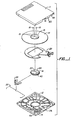
- Fig. 1 shows an exploded perspective view of a disk cartridge assembly incorporating the invention.
- a disk cartridge housing having a mating top casing 11 and a bottom casing 12 encloses a rigid disk assembly comprising a recording disk 14, an upper disc clamp 15 and a lower flange 16.
- Disk 14 is secured between disc clamp 15 and hub 16 by a plurality of fastener bolts 18 received through bores 19 in upper disc clamp 15 and threaded into tapped bores 20 in lower hub 16.
- the disk assembly is retained within the cartridge housing by means of a releasable hub locking mechanism which includes a pair of lever plates 25 (only one of which is shown), a torsion spring 26 for each lever plate 25, and cooperating elements formed in the inner base surface of bottom casing 12.
- An airflow plate 22 is arranged to provide distribution of outside air within the disk cartridge when the disk is rotating.
- a pair of mating bored bosses is provided, one each in top casing portion 11 and bottom casing portion 12 generally in a corner region thereof, the bosses being designated with reference numerals 32, respectively, and the bosses being physically located so that their axes mate when the two half portions 11, 12 of the casing are assembled together.
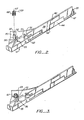
- Each half casing portion 11, 12 is also provided with a laterally extending slot 35 dimensioned to receive a door slide 38.
- Door slide 38 has a rectangular aperture 40 formed therein which is so located along the length of slide 38 as to provide registration with the transducer access opening when the slide is in the open position, the access opening being formed by u-shaped-apertures 41, 42 formed in the front access wall of the cartridge defined by forward walls 43, 44.
- a second pair of u-shaped openings in access walls 43, 44 and designated by reference numerals 46, 47 provides an air inlet passage which is open for fluid communication with the mouth of air flow plate 22 when door slide 38 is moved to the open position.
- clevis member On the left end of door slide 38 is a clevis member consisting of a pair of flanges 51, 52 joined by a clevis pin 53.
- bottom casing portion 12 Also molded into bottom casing portion 12 is an additional bored boss 55 for a purpose to be described.
- crank 60 has a lower journal 61 and an upper journal 62.
- the length of lower journal 61 is substantially greater than that of upper journal 62 so that crank 60 is vertically stable when journal 61 is received in the bore 33 formed in boss 32.
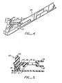
- a torsion spring 67 is placed over boss 32 with one end 68 thereof bearing against an abutment stop formed by a circular stiffener wall rib 70 (Fig 2).
- spring 67 is wound in the clockwise direction as viewed in Fig. 2 to provide a predetermined amount of spring tension. With the spring wound in tension, a temporary pin 72 is inserted into bore 56 of spare boss 55 and free arm 69 offspring 67 is permitted to bear against pin 72 (Fig. 3). This temporarily holds spring 67 under tension pending further assembly.
- crank 60 is maneuvered close to boss 32 and a forked end 64 is maneuvered into an embracing position with respect to door slide clevis pin 53 as shown. Thereafter, journal 61 is inserted-into bore 33 to the position shown in section in Fig. 5, after which temporary pin 72 is removed, thereby releasing upper arm 69 of spring 67 to bear against the stop member 75 depending downwardly from crank arm 64.
- the assembly of the door operating mechanism is now complete and the cartridge assembly is finished in the usual manner.
- the improved door operating mechanism of the invention permits the assembly operation to be rapidly done without the need for any particular expertise. Specifically, by forming lower journal 61 with the extensive length illustrated, crank 60 cannot tip from the vertical when biased by upper arm 69 of spring 67. In addition, by providing the spare boss 55 and using the temporary pin 72, the spring tensioning step and the crank installation step are greatly simplified.
Landscapes
- Feeding And Guiding Record Carriers (AREA)
Applications Claiming Priority (2)
| Application Number | Priority Date | Filing Date | Title |
|---|---|---|---|
| US443770 | 1982-11-22 | ||
| US06/443,770 US4559575A (en) | 1982-11-22 | 1982-11-22 | Removable disk cartridge with improved door operating mechanism |
Publications (3)
| Publication Number | Publication Date |
|---|---|
| EP0109668A2 true EP0109668A2 (de) | 1984-05-30 |
| EP0109668A3 EP0109668A3 (en) | 1985-09-11 |
| EP0109668B1 EP0109668B1 (de) | 1988-11-09 |
Family
ID=23762127
Family Applications (1)
| Application Number | Title | Priority Date | Filing Date |
|---|---|---|---|
| EP83111519A Expired EP0109668B1 (de) | 1982-11-22 | 1983-11-17 | Türschiebermechanismus für ein Diskettengehäuse |
Country Status (5)
| Country | Link |
|---|---|
| US (1) | US4559575A (de) |
| EP (1) | EP0109668B1 (de) |
| JP (1) | JPS59104756A (de) |
| CA (1) | CA1210502A (de) |
| DE (1) | DE3378436D1 (de) |
Families Citing this family (27)
| Publication number | Priority date | Publication date | Assignee | Title |
|---|---|---|---|---|
| US4717981A (en) * | 1983-08-04 | 1988-01-05 | Syquest Technology | Hard disc cartridge arrangement with an automatically activated door |
| JPS6166272A (ja) * | 1984-09-10 | 1986-04-05 | Clarion Co Ltd | デイスクカ−トリツジ |
| US4864452A (en) * | 1988-02-26 | 1989-09-05 | Syquest Technology | Removable cartridge with lockable access door |
| USD339798S (en) | 1991-06-28 | 1993-09-28 | Syquest Technology, Inc. | Removable cartridge with a 21/2 inch form factor for a disk drive |
| USD342062S (en) | 1991-10-15 | 1993-12-07 | Syquest Technology, Inc. | 3-1/2 inch disk cartridge |
| US5253133A (en) * | 1992-01-03 | 1993-10-12 | Cct Inc. | Portable modular hard disk drive |
| USD350115S (en) | 1992-11-13 | 1994-08-30 | Syquest Technology, Inc. | Cartridge with a 1.8 inch form factor for a removable cartridge disk drive |
| US5440436A (en) * | 1992-11-13 | 1995-08-08 | Syquest Technology, Inc. | Removable cartridge disk drive with a 1.8 inch form factor |
| JP2000501218A (ja) * | 1995-06-07 | 2000-02-02 | アイオメガ コーポレイション | カートリッジシェルに対し磁気ディスクをクランプするためのカム機構 |
| DE841661T1 (de) * | 1995-06-07 | 1998-09-24 | Iomega Corp | Plattenkassette mit Antiklapperverfahren |
| US5671109A (en) * | 1995-06-07 | 1997-09-23 | Iomega Corporation | Disk drive cartridge door |
| JPH1166791A (ja) * | 1997-08-13 | 1999-03-09 | Sony Corp | ディスクカセット |
| US6147962A (en) * | 1997-11-26 | 2000-11-14 | Srinivasan; Thiruppathy | Data storage cartridge having a restraining mechanism |
| JPH11238334A (ja) * | 1997-12-18 | 1999-08-31 | Fuji Photo Film Co Ltd | 磁気テープカートリッジ |
| JP3695921B2 (ja) | 1997-12-22 | 2005-09-14 | 富士写真フイルム株式会社 | 磁気テープカートリッジ |
| USD411533S (en) | 1998-05-12 | 1999-06-29 | Castlewood Systems, Inc. | Element of an audio video and computer data cartridge |
| USD418828S (en) * | 1998-05-12 | 2000-01-11 | Castlewood Systems, Inc. | Element of an audio, video and computer data cartridge |
| USD424048S (en) * | 1998-05-12 | 2000-05-02 | Castlewood Systems, Inc. | Video and computer data cartridge |
| USD410644S (en) | 1998-05-12 | 1999-06-08 | Castlewood Systems, Inc. | Audio, video, and computer data cartridge |
| US6141185A (en) | 1998-08-25 | 2000-10-31 | Iomega Corporation | Anti-rattle mechanism for cartridge |
| US6452821B1 (en) * | 2000-10-26 | 2002-09-17 | Sheng Hsin Liao | Voltage-transforming device having a wire-winding mechanism |
| US6304476B1 (en) * | 2000-10-26 | 2001-10-16 | Sheng-Hsin Liao | Voltage transformer having a wire-winding mechanism |
| JP4054236B2 (ja) * | 2002-08-30 | 2008-02-27 | 富士フイルム株式会社 | 記録テープカートリッジ |
| JP4656817B2 (ja) * | 2003-03-27 | 2011-03-23 | Tdk株式会社 | テープカートリッジ用ドア部材およびテープカートリッジ |
| US7077353B1 (en) * | 2003-11-05 | 2006-07-18 | Storage Technology Corporation | Tape cartridge with movable access door |
| US7317593B1 (en) | 2003-11-05 | 2008-01-08 | Storage Technology Corporation | Tape cartridge with pivotable access door |
| US6955319B1 (en) * | 2003-12-17 | 2005-10-18 | Storage Technology Corporation | Tape cartridge with access door |
Family Cites Families (5)
| Publication number | Priority date | Publication date | Assignee | Title |
|---|---|---|---|---|
| US3593327A (en) * | 1968-10-24 | 1971-07-13 | Singer Co | Memory-disc cartridge with loading mechanism |
| US4320430A (en) * | 1980-04-10 | 1982-03-16 | Memorex Mini Disc Drive Corporation | Recording disc cartridge closure mechanism |
| US4399480A (en) * | 1981-03-30 | 1983-08-16 | Disctron, Inc. | Head access door, opening mechanism and method of sealing |
| US4412260A (en) * | 1981-04-24 | 1983-10-25 | Magnetic Peripherals Inc. | Cartridge receiver mechanism |
| US4459628A (en) * | 1982-04-19 | 1984-07-10 | Cipher Data Products, Inc. | Disk cartridge |
-
1982
- 1982-11-22 US US06/443,770 patent/US4559575A/en not_active Expired - Fee Related
-
1983
- 1983-11-15 CA CA000441193A patent/CA1210502A/en not_active Expired
- 1983-11-17 DE DE8383111519T patent/DE3378436D1/de not_active Expired
- 1983-11-17 EP EP83111519A patent/EP0109668B1/de not_active Expired
- 1983-11-22 JP JP58218798A patent/JPS59104756A/ja active Granted
Also Published As
| Publication number | Publication date |
|---|---|
| CA1210502A (en) | 1986-08-26 |
| US4559575A (en) | 1985-12-17 |
| JPH0412546B2 (de) | 1992-03-04 |
| JPS59104756A (ja) | 1984-06-16 |
| EP0109668A3 (en) | 1985-09-11 |
| EP0109668B1 (de) | 1988-11-09 |
| DE3378436D1 (en) | 1988-12-15 |
Similar Documents
| Publication | Publication Date | Title |
|---|---|---|
| EP0109668B1 (de) | Türschiebermechanismus für ein Diskettengehäuse | |
| EP0097964B1 (de) | Sperrelement für ein Deckel einer Magnetbandkassette | |
| JPH0935375A (ja) | テープ駆動装置 | |
| EP0124873A2 (de) | Anordnung einer Federstaubschutzdeckelverriegelung für Bandkassette | |
| EP0125688A2 (de) | Bandkassette | |
| US4550355A (en) | Removable disk cartridge with improved hub locking mechanism | |
| JPS6339993B2 (de) | ||
| JPH07333723A (ja) | 磁気記憶部付きフィルムを用いるカメラ | |
| US5642245A (en) | Tape cassette information detecting mechanism and reel lock releasing mechanism for recording and reproducing apparatus | |
| US6014293A (en) | Single reel cartridge erasure preventing device housing with post | |
| JPH0216440Y2 (de) | ||
| US6450434B1 (en) | Wide tape holding frame | |
| KR100240304B1 (ko) | 테이프카세트 | |
| US5691868A (en) | Disk cartridge with shutter and slider, and method of connecting them | |
| GB2157265A (en) | Magnetic tape cassette | |
| JPH08191191A (ja) | 蓋体のクリック機構 | |
| JP3154203B2 (ja) | テープ駆動装置 | |
| JPS6312465Y2 (de) | ||
| JPS6087461A (ja) | カセツト装着装置 | |
| JPH0341347Y2 (de) | ||
| JPS6316070Y2 (de) | ||
| JPS637965Y2 (de) | ||
| JP2533714Y2 (ja) | カセットハーフ用機器の扉開閉機構 | |
| JP2748480B2 (ja) | カセットホルダー装置 | |
| JPH11306717A (ja) | 磁気テープカセット |
Legal Events
| Date | Code | Title | Description |
|---|---|---|---|
| PUAI | Public reference made under article 153(3) epc to a published international application that has entered the european phase |
Free format text: ORIGINAL CODE: 0009012 |
|
| AK | Designated contracting states |
Designated state(s): DE FR GB IT SE |
|
| 17P | Request for examination filed |
Effective date: 19841122 |
|
| PUAL | Search report despatched |
Free format text: ORIGINAL CODE: 0009013 |
|
| AK | Designated contracting states |
Designated state(s): DE FR GB IT SE |
|
| 17Q | First examination report despatched |
Effective date: 19870603 |
|
| GRAA | (expected) grant |
Free format text: ORIGINAL CODE: 0009210 |
|
| AK | Designated contracting states |
Kind code of ref document: B1 Designated state(s): DE FR GB IT SE |
|
| ITF | It: translation for a ep patent filed | ||
| REF | Corresponds to: |
Ref document number: 3378436 Country of ref document: DE Date of ref document: 19881215 |
|
| ET | Fr: translation filed | ||
| PLBE | No opposition filed within time limit |
Free format text: ORIGINAL CODE: 0009261 |
|
| STAA | Information on the status of an ep patent application or granted ep patent |
Free format text: STATUS: NO OPPOSITION FILED WITHIN TIME LIMIT |
|
| 26N | No opposition filed | ||
| PGFP | Annual fee paid to national office [announced via postgrant information from national office to epo] |
Ref country code: FR Payment date: 19901012 Year of fee payment: 8 |
|
| PGFP | Annual fee paid to national office [announced via postgrant information from national office to epo] |
Ref country code: GB Payment date: 19901016 Year of fee payment: 8 |
|
| PGFP | Annual fee paid to national office [announced via postgrant information from national office to epo] |
Ref country code: SE Payment date: 19901019 Year of fee payment: 8 |
|
| PGFP | Annual fee paid to national office [announced via postgrant information from national office to epo] |
Ref country code: DE Payment date: 19901030 Year of fee payment: 8 |
|
| ITTA | It: last paid annual fee | ||
| PG25 | Lapsed in a contracting state [announced via postgrant information from national office to epo] |
Ref country code: GB Effective date: 19911117 |
|
| PG25 | Lapsed in a contracting state [announced via postgrant information from national office to epo] |
Ref country code: SE Effective date: 19911118 |
|
| GBPC | Gb: european patent ceased through non-payment of renewal fee | ||
| PG25 | Lapsed in a contracting state [announced via postgrant information from national office to epo] |
Ref country code: FR Effective date: 19920731 |
|
| PG25 | Lapsed in a contracting state [announced via postgrant information from national office to epo] |
Ref country code: DE Effective date: 19920801 |
|
| REG | Reference to a national code |
Ref country code: FR Ref legal event code: ST |
|
| EUG | Se: european patent has lapsed |
Ref document number: 83111519.1 Effective date: 19920604 |