EP0109687B1 - Werkstück-Nachlaufsteuervorrichtung für die Steuerung von Schleifmaschinen - Google Patents
Werkstück-Nachlaufsteuervorrichtung für die Steuerung von Schleifmaschinen Download PDFInfo
- Publication number
- EP0109687B1 EP0109687B1 EP83111618A EP83111618A EP0109687B1 EP 0109687 B1 EP0109687 B1 EP 0109687B1 EP 83111618 A EP83111618 A EP 83111618A EP 83111618 A EP83111618 A EP 83111618A EP 0109687 B1 EP0109687 B1 EP 0109687B1
- Authority
- EP
- European Patent Office
- Prior art keywords
- workpiece
- grinding wheel
- grinding
- curvature
- longitudinal axis
- Prior art date
- Legal status (The legal status is an assumption and is not a legal conclusion. Google has not performed a legal analysis and makes no representation as to the accuracy of the status listed.)
- Expired
Links
- 230000003750 conditioning effect Effects 0.000 title 1
- 239000000463 material Substances 0.000 claims abstract description 7
- 238000005259 measurement Methods 0.000 abstract description 17
- 238000000034 method Methods 0.000 description 9
- 239000002344 surface layer Substances 0.000 description 4
- 239000012530 fluid Substances 0.000 description 2
- 239000004575 stone Substances 0.000 description 2
- 230000000593 degrading effect Effects 0.000 description 1
- 230000001788 irregular Effects 0.000 description 1
- 239000010410 layer Substances 0.000 description 1
- 239000002994 raw material Substances 0.000 description 1
- 238000005096 rolling process Methods 0.000 description 1
Images

Classifications
-
- B—PERFORMING OPERATIONS; TRANSPORTING
- B24—GRINDING; POLISHING
- B24B—MACHINES, DEVICES, OR PROCESSES FOR GRINDING OR POLISHING; DRESSING OR CONDITIONING OF ABRADING SURFACES; FEEDING OF GRINDING, POLISHING, OR LAPPING AGENTS
- B24B49/00—Measuring or gauging equipment for controlling the feed movement of the grinding tool or work; Arrangements of indicating or measuring equipment, e.g. for indicating the start of the grinding operation
Definitions
- This invention relates to grinding machinery for workpieces, such as billets, and more particularly, to a device for maintaining a grinding wheel in contact with a surface of a workpiece despite bowing or deformation of a surface adjacent to the surface being actually ground of the workpiece, as set forth in the preamble of claim 1.
- a device for maintaining a grinding wheel in contact with a surface of a workpiece despite bowing or deformation of a surface adjacent to the surface being actually ground of the workpiece as set forth in the preamble of claim 1.
- Such device is known from DE-B-2 510 555.
- a billet is often the raw material for a rolling process in which the billet is flattened and formed into a finished product.
- These billets often contain surface imperfections which, if not removed, are carried through to the finished product. Accordingly, these imperfections are normally removed in a grinding process called "spotting" in which a rotating grinding wheel is held against the surface imperfection until the surface imperfection is removed.
- the surfaces of billets are also normally coated with a layer of oxides and other material. This surface layer must also be removed in order to prevent the surface layer from degrading the quality of the finished product.
- the surface layer is normally removed in a process called “skinning" in which the billet reciprocates beneath the grinding wheel while the grinding wheel is held in contact with the billet.
- the skinning process is often performed automatically.
- the grinding pressure of the wheel against the workpiece is automatically controlled while the workpiece reciprocates back and forth adjacent the grinding wheel, and the grinding wheel steps across the workpiece an incremental distance each grinding pass.
- the automatic skinning process is generally performed only on the top surface of the workpiece.
- the workpiece In order to grind all four surfaces of a rectangular workpiece, the workpiece is sequentially rotated from one surface to the next so that the surface to be skinned is facing upwardly.
- grinding the upper surface of a workpiece is relatively straightforward since the grinding force exerted by the grinding wheel in a downward direction can be adjusted by a control signal derived from such parameters as a horsepower or grinding force. It is possible to use such techniques even though the workpiece is curved or bowed upwardly since the grinding wheel is automatically moved in a vertical direction to maintain the horsepower, grinding force, or other parameter at a target value. In contrast, grinding the sides of a workpiece presents problems not encountered with grinding the top surface of the workpiece. Although operating parameters such as grinding power or grinding force can be used to control actuators moving the grinding wheel in a horizontal direction, bowing of the workpiece in a vertical direction prevents the grinding wheel from uniformly contacting the sides of the workpiece.
- the grinding apparatus disclosed in the aforementioned DE-B-2 510 555 is used for grinding plate-like work pieces having irregular edges, such as natural stone slabs.
- a head rotatably supporting a plurality of frontal grinding wheels is moved transversely to the rotating axis of said wheels across said stone slabs.
- Switches connected to driving means and supported by said head and provided with sensor leaves detect the edges of the slab being ground, so as to change the direction of movement of said head.
- the grinding wheel sequentially removes longitudinal strips of material from the surface to be ground as the wheel sequentially indexes in the transverse direction across the surface.
- the inventive control device applies an offset to the grinding wheel in the transverse direction.
- the offset corresponds to the curvature of the workpiece so that the longitudinal strips removed by the grinding wheel are curved to conform to the curvature of the workpiece.
- the curvature of the workpiece is determined by recording the position of the grinding wheel along the length of the workpiece as an adjacent surface is previously ground. This results in a set of offsets taken at points along the longitudinal axis of the workpiece.
- the offsets are then summed with an indexing signal controlling the position of the grinding wheel in the transverse direction, with the offset being selected by measuring the longitudinal position of the workpiece with respect to the grinding wheel.
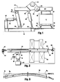
- FIG. 1 A typical apparatus for grinding workpieces, such as billets, is illustrated in Figs. 1 and 2.
- the apparatus includes a stationary, rigid floor frame 16, from which a support 18 is pivotally mounted at 20.
- the opposite end of the pivotal support 18 is pivotally secured at 22 to a horizontally disposed grinding wheel support arm 24.
- a conventional hydraulic actuator 26 is also pivotally mounted to the floor frame 16 at 28 and to the grinding wheel support arm 24 at 30.
- the adjustment is relatively slight so that the pivotal support 18 and hydraulic actuator 26 somewhat approximate a parallelogram.
- a grinding wheel 32 mounted on a motor 34 through a spindle 36 is carried at the end of the horizontally disposed grinding wheel support arm 24. Hydraulic fluid flowing into and out of the hydraulic actuator 26 in a conventional manner produces primarily vertical movement of the grinding wheel 32.
- the structure of the support 18 and hydraulic actuator 26 cause a second hydraulic actuator 40 to produce primarily horizontal movement of the grinding wheel 32.
- the hydraulic actuator 40 is pivotally connected to the floor frame 16 at 42 and to the pivotal support 18 at 44.
- the rotational positions of the pivotal support 18 with respect to the frame 16 and the support arm 24 are sensed by conventional position encoders 46, 48, respectively. As explained in detail below, these encoders 46, 48 allow the position of the grinding wheel 32 to be constantly determined as the actuators 26, 40 vary the positions of the pivotal support 18 and support arm 24.
- the workpiece WP is carried by a manipulator car C and is securely held thereon by clamp members 50.
- the car C is supported on rails 52 by a pair of wheels 54.
- the car C and, hence, the workpiece WP reciprocate beneath the grinding wheel 32 as the car C moves along the rails 52.
- a cable 60 connected to one end of the carriage C engages a drum 62 which is rotated by a hydraulic motor 64 in accordance with a control signal in a conventional manner.
- the cable 60 extends beneath the rails 52 and engages a freely rotating sheave 66 at the other end of the rails 52.
- rotation of the drum 62 moves the carriage C along the rails 52.
- the position of the car C and, hence, the workpiece WP with respect to the grinding wheel 32 is measured by a rotary encoder 68 rotating with the drum 62.
- the grinding system as described above is conventional and is described in greater detail in U.S. Patent No. 4,248,019, which is incorporated herein by reference.
- the output of the encoder 68, as well as the outputs of the encoders 46, 48 (Fig. 1) for sensing the position of the grinding wheel 32, are applied to a conventional computer 69 operating under a program of instructions described in detail below.
- the computer generates outputs to respective conventional servo valves (not shown) which control the flow of hydraulic fluid to the actuators 26, 40 in a manner well known to those skilled in the art.
- a workpiece WP such as a billet
- a workpiece WP is initially placed on a conventional charge table 70.
- the carriage C is then moved along the rails 52 and the workpiece WP is loaded onto the carriage C by conventional handling means.
- the carriage C then moves toward a position beneath the grinding wheel 32 and the grinding wheel 32 is lowered into contact with one of the exposed surfaces of the workpiece WP.
- the workpiece WP then reciprocates back and forth beneath the grinding wheel 32.
- the hydraulic actuator 40 is primarily energized to control the force exerted by the grinding wheel 32 against the vertical surface of the workpiece WP.
- the hydraulic actuator 26 is energized primarily to step or "index" the grinding wheel vertically across the surface to be ground after each grinding pass.
- the actuators 26, 40 will reverse roles, with the actuator 26 controlling the grinding force and the actuator 40 indexing the grinding wheel 32 across the surface to be ground.
- the workpiece WP is turned over to expose the other two surfaces of the workpiece WP to the grinding wheel 32.
- the grinding wheel 32 could, of course, be used to grind only one surface (horizontal or vertical), with the workpiece WP being turned 90° after each surface is ground.
- the carriage C After grinding, the carriage C is moved along the rails 52 to a discharge position, where the workpiece WP is loaded onto a conventional discharge table 72 by conventional handling means.
- the entire operation of the system is controlled in a conventional manner, either manually or semiautomatically, by an operator in a cab 74, as is well known to those skilled in the art.
- One such workpiece grinding system is disclosed in previously mentioned U.S. Patent No. 4,248,019.
- the above-described grinding apparatus is one design used to grind elongated workpieces, such as billets.
- other types of grinding apparatus are also used to perform grinding operations on workpieces of various types.
- inventive control system is described with reference to the grinding apparatus of Figs. 1 and 2, it will be understood that the inventive control device can also be used with other grinding apparatuses.
- Fig. 3 shows a typical workpiece, such as a slab, bloom, or billet.
- the workpiece is shown in profile or elevational view in the position illustrated in Fig. 1. Thus, it is the vertical side surface of the workpiece WP that is being ground. It will be apparent that the workpiece WP is vertically bowed in that is is markedly curved about an axis that extends in the horizontal direction.
- the carriage C would reciprocate in front of the grinding wheel 32, thereby allowing the grinding wheel 32 to remove a horizontal strip of material from the side surface of the workpiece WP.
- the grinding wheel 32 would be "indexed” or moved vertically in stepped increments after each grinding pass, thereby sequentially removing the surface layer of the workpiece in a series of horizontal strips.
- the grinding wheel 32 could easily move horizontally above the workpiece so that when the workpiece reverses direction, the workpiece would contact the top surface and not the side surface of the workpiece WP. Also, the grinding wheel 32 would remove more material near the edge of the workpiece WP, thus producing a nonuniform depth of removal on the side surface of the workpiece WP. While the problem is being discussed with reference to grinding the sides of workpieces having a vertical bow, it will be understood that the problem also exists in grinding the upper surface of a workpiece having a horizontal bow.
- the inventive control device solves the aforementioned problems by recording the curvature of the workpiece WP by recording a set of measurements indicative of the distance from a reference line or plane, such as "Profile A”, to a measurement line or plane, such as “Profile B", that is curved in the same manner as the workpiece WP.
- the measurements can be made during grinding of the upper surface of the workpiece WP by recording the position of the grinding wheel 32 at spaced-apart points along the length of the workpiece WP.
- the result is a set of measurements ⁇ 1 , A 2 , ..., An that indicate the curvature of the workpiece WP from a plane of reference.
- curvature measurements A 1 , A 2 , ..., An have been obtained, they can be summed with position command signals controlling the vertical position of the grinding wheel 32 as the workpiece WP moves during each grinding pass. As a result, these curvature measurements are used as offsets to cause the grinding wheel 32 to follow the curved line "Profile B" instead of the horizontal line “Profile A”.
- Individual curvature measurements are selected by noting the position of the workpiece, as indicated by the position encoder 68, to determine the portion of the workpiece WP opposite the grinding wheel 32. The curvature measurement for that portion of the workpiece WP is then summed with the vertical position command signal to the actuators 26, 40 to ensure the correct vertical position of the grinding wheel 32.
- the vertical position of the grinding wheel 32 is calculated from signals output by the encoders 46, 48 by the computer 69.
- the computer 69 also determines the position of the workpiece WP from the output of the encoder 68.
- the computer 69 then records the vertical position of the grinding wheel 32 at specific locations while grinding the upper surface of the workpiece WP.
- the computer 69 then generates respective offset signals for servo valves controlling the actuators 26, 40 when the side of the workpiece WP is being ground.
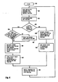
- the software for controlling the operation of the computer 69 is illustrated in Fig. 4.
- the program is entered at 80 and proceeds to 82, where the outputs of the encoders 46,48 are read, and the vertical position of the grinding wheel 32 corresponding to the angular positions is calculated in accordance with known geometric principles.
- the position of the manipulator car C is then calculated at 84 from the output of the encoder 68. If a store data pushbutton 86 (Fig. 2) is closed, this fact is detected at 86 to cause the program to branch to 88, where the timing of the closure of switch 86 is examined.
- the program stores a set of grinding wheel position measurements at 90, along with an indication of the position of the workpiece WP at the point where the measurement is taken. The grinding wheel 32 is then moved to the starting location for grinding the sides of the workpiece WP.
- the vertical position of the grinding wheel 32 is then measured at 92 and subtracted from each stored vertical position measurement to provide the offsets A 1 , A 2 , ..., A", which should be added to or subtracted from the vertical position command signals during each grinding pass while grinding the sides. These offset values are then stored at 94.
- the computer 69 After all of the offsets have been stored at 94, the computer 69 outputs a command at 98 before returning to 82.
- the vertical position of the grinding wheel 32 is once again read at 82 and the longitudinal position of the workpiece is read at 84.
- the store switch 86 will no longer be closed, so the program will now branch to 100, where the offset value for the current position of the workpiece that was read at 84 is retrieved.
- This offset value is then added to the current vertical command at 102 to generate a command signal indicative of the desired position of the grinding wheel to compensate for curvature of the workpiece about an axis normal to the surface being ground.
- This command is once again output at 98 before returning to 82 to process a new offset corresponding to the new relative position between the workpiece WP and the grinding wheel 32 along the longitudinal axis of the workpiece WP.
- the signals for controlling the grinding force of the grinding wheel 32 and for indexing the grinding wheel 32 across the surface to be ground are generated in a conventional manner, such as described in previously mentioned U.S. Patent No. 4,248,019.
- a sensing device 110 is positioned directly opposite the workpiece 32 for measuring the vertical position of the top surface of the workpiece at the same longitudinal position of the workpiece currently being ground by the grinding wheel 32.
- the sensing device may include a feeler arm 112 having a roller 114 continuously contacting the upper surface of the workpiece WP.
- the feeler arm 112 is pivotally mounted at 116.
- the rotational position of the arm 112 is measured by a conventional rotary encoder 118 or potentiometer.
- the output of the encoder 118 thus continuously generates an offset that can be summed with the command signal to cause the grinding wheel 32 to follow a curved path corresponding to the curvature of the workpiece.
- the grinding wheel 32 is described as being used for grinding the vertical sides of the workpiece WP, it will be understood that the same principle applies to grinding the upper surface of the workpiece WP when the workpiece WP is curved about a vertical axis extending normal to the upper surface being ground.
Landscapes
- Engineering & Computer Science (AREA)
- Mechanical Engineering (AREA)
- Constituent Portions Of Griding Lathes, Driving, Sensing And Control (AREA)
- Automatic Control Of Machine Tools (AREA)
- Grinding And Polishing Of Tertiary Curved Surfaces And Surfaces With Complex Shapes (AREA)
- Finish Polishing, Edge Sharpening, And Grinding By Specific Grinding Devices (AREA)
Claims (2)
- Steuervorrichtung für eine Vorbereitungs-Schleifmaschine zum Schleifen langgestreckter Werkstücke, mit einer Stelleinrichtung (26, 40) zum Bewegen des Schleifrades (32) in einer ersten Richtung senkrecht zu einer zu schleifenden Fläche des Werkstücks (WP) und in einer zweiten Richtung, die parallel zu der genannten Fläche und senkrecht zur Längsachse des Werkstücks (WP) verläuft, einer ersten Wandlereinrichtung (34) zum Messen eines Betriebsparameters, der für die Stärke der Schleifwirkung des Schleifrades (32) kennzeichnend ist, einer ersten Steuereinrichtung (in 69), die einen Ausgang von der ersten Wandlereinrichtung (34) erhält, um die Stelleinrichtung (26, 40) in der ersten Richtung zu steuern, um den genannten Betriebsparameter auf einem vorgegebenen Wert zu halten, und einer Werkstückantriebseinrichtung (60, 62, 64, 66) zum Hin- und Herbewegen des Werkstücks (WP) längs seiner Längsachse in bezug auf das Schleifrad (32) während mehrerer Schleifdurchgänge, dadurch gekennzeichnet, daß die Steuereinrichtung enthält:einen Werkstückpositionswandler (68) zum Bestimmen und Erzeugen eines Werkstückpositionssignals, das die Position des Werkstücks (WP) in bezug auf das Schleifrad (32) längs der Längsachse des Werkstücks (WP) angibt;einen Schleifradpositionswandler (46, 48) zum Bestimmen und Erzeugen eines Schleifradpositionssignals, das die Position des Schleifrades (32) in der zweiten Richtung angibt;eine Speichereinrichtung (in 69), die das Werkstückpositionssignal und das Schleifradpositionssignal entgegennimmt, um die Position des Schleifrades (32) und des Werkstücks (WP) aufzuzeichnen, während das Schleifrad (32) mit einer ersten Fläche des Werkstücks (WP) in Berührung ist, die einer zweiten, später zu schleifenden Fläche benachbart ist, um dadurch eine Aufzeichnung der Krümmung der ersten Fläche zu erzeugen;eine Kompensationseinrichtung (in 69), die auf die Speichereinrichtung (in 69) und den Werkstückpositionswandler (68) anspricht, um die Stelleinrichtung (26, 40) so zu steuern, daß das Schleifrad (32) in der zweiten Richtung während des Schleifens der zweiten Fläche bewegt wird, wenn sich das Werkstück (WP) gegenüber dem Schleifrad (32) längs seiner Längsachse bewegt, wobei der Bewegungsumfang in der zweiten Richtung in jeder Position des Werkstücks (WP) proportional zu dem Schleifradpositionssignal an der entsprechenden Position des Werkstücks (WP) ist, undeine Indexeinrichtung (in 69), die wirkungsmäßig der Stelleinrichtung (26, 40) zugeordnet ist, um das Schleifrad (32) selektiv in der zweiten Richtung über die zweite Fläche des Werkstücks (WP) zu bewegen, um nacheinander sich in Längsrichtung erstreckende Materialstreifen von der zweiten Fläche zu entfernen, wobei die Bewegung des Schleifrades (32) in der zweiten Richtung, die von der Indexeinrichtung (in 69) hervorgerufen wird, mit der Bewegung des Schleifrades (32) in der zweiten Richtung summiert wird, die von der Kompensationseinrichtung (in 69) hervorgerufen wird, um dadurch zu bewirken, daß die sich in Längsrichtung erstreckenden Streifen, die von dem Schleifrad (32) entfernt wreden, eine Krümmung haben, die der Krümmung des Werkstücks (WP) um eine Achse entspricht, die sich in der ersten Richtung erstreckt.
Priority Applications (1)
| Application Number | Priority Date | Filing Date | Title |
|---|---|---|---|
| AT83111618T ATE35927T1 (de) | 1982-11-22 | 1983-11-21 | Werkstueck-nachlaufsteuervorrichtung fuer die steuerung von schleifmaschinen. |
Applications Claiming Priority (2)
| Application Number | Priority Date | Filing Date | Title |
|---|---|---|---|
| US443168 | 1982-11-22 | ||
| US06/443,168 US4501094A (en) | 1982-11-22 | 1982-11-22 | Workpiece profile-following control system for conditioning grinders |
Publications (3)
| Publication Number | Publication Date |
|---|---|
| EP0109687A2 EP0109687A2 (de) | 1984-05-30 |
| EP0109687A3 EP0109687A3 (en) | 1985-10-30 |
| EP0109687B1 true EP0109687B1 (de) | 1988-07-27 |
Family
ID=23759682
Family Applications (1)
| Application Number | Title | Priority Date | Filing Date |
|---|---|---|---|
| EP83111618A Expired EP0109687B1 (de) | 1982-11-22 | 1983-11-21 | Werkstück-Nachlaufsteuervorrichtung für die Steuerung von Schleifmaschinen |
Country Status (6)
| Country | Link |
|---|---|
| US (1) | US4501094A (de) |
| EP (1) | EP0109687B1 (de) |
| JP (1) | JPS59142063A (de) |
| AT (1) | ATE35927T1 (de) |
| CA (1) | CA1213961A (de) |
| DE (1) | DE3377475D1 (de) |
Cited By (1)
| Publication number | Priority date | Publication date | Assignee | Title |
|---|---|---|---|---|
| CN101879695A (zh) * | 2010-06-23 | 2010-11-10 | 常州明豪新金属材料有限公司 | 铜带剪切面除氧化层装置 |
Families Citing this family (11)
| Publication number | Priority date | Publication date | Assignee | Title |
|---|---|---|---|---|
| EP0142072A3 (de) * | 1983-11-15 | 1986-12-30 | Aida Engineering Ltd. | Schleifroboter |
| AU3583084A (en) * | 1983-12-10 | 1985-06-13 | Aida Engineering Ltd. | Playback grinding robot |
| SE444648B (sv) * | 1984-09-03 | 1986-04-28 | Robert Ek | Forfarande och anordning for slipning av skridskos glidyta |
| DE3834279A1 (de) * | 1988-10-08 | 1990-04-12 | Bwg Bergwerk Walzwerk | Verfahren und anlage zur spanabhebenden bearbeitung von brammen und bloecken |
| US6876899B2 (en) | 2002-01-18 | 2005-04-05 | Vulcan Engineering Co., Inc. | Method for automatic riser gate removal compensating for variance in casting |
| US20030196528A1 (en) * | 2002-04-19 | 2003-10-23 | Cooper Christopher W. | Compliant cutoff saw assembly |
| TWI490061B (zh) | 2009-03-19 | 2015-07-01 | Siemag Gmbh | 用於將連續鑄造產物研磨的裝置 |
| CN103406824A (zh) * | 2013-09-02 | 2013-11-27 | 丹阳利华电子有限公司 | 铜带剪切面除氧化层装置 |
| CN104669093B (zh) * | 2015-03-19 | 2017-10-20 | 南通江海港建设工程有限公司 | 可自由调节打磨压力的打磨装置 |
| FR3054158B1 (fr) * | 2016-07-21 | 2019-06-28 | Comau France | Machine-outil d’usinage |
| CN118650503B (zh) * | 2024-07-19 | 2025-11-18 | 深圳数马电子技术有限公司 | 刀具的阶梯曲面磨削方法、装置、数控机和存储介质 |
Family Cites Families (14)
| Publication number | Priority date | Publication date | Assignee | Title |
|---|---|---|---|---|
| US2073786A (en) * | 1932-11-14 | 1937-03-16 | Gen Spring Bumper Corp | Polishing machine |
| US3134204A (en) * | 1962-09-28 | 1964-05-26 | Bliss E W Co | Grinding machine |
| GB1127434A (en) * | 1964-12-01 | 1968-09-18 | Churchill Machine Tool Co Ltd | Improvements in grinding machines |
| DE2159020A1 (de) * | 1971-11-29 | 1973-05-30 | Metabowerke Kg | Verfahren und vorrichtung zum kontinuierlichen schleifen bzw. polieren langgestreckter werkstuecke |
| JPS5222471B2 (de) * | 1973-10-05 | 1977-06-17 | ||
| US3953943A (en) * | 1975-02-27 | 1976-05-04 | Shimadzu Seisakusho Ltd. | Apparatus for automatically detecting and eliminating flaws on slabs or billets |
| DE2510555B1 (de) * | 1975-03-11 | 1976-09-02 | Georg Zankl | Schaltvorrichtung fuer den vorschub und die umkehr der vorschubbewegung eines mit stirnschleifscheiben versehenen schleifkopfes |
| US4100700A (en) * | 1976-12-07 | 1978-07-18 | Western Gear Corporation | Workpiece conditioning grinder system |
| US4112626A (en) * | 1977-04-08 | 1978-09-12 | Daido Tokushuko Kabushiki Kaisha | Automatic deseaming apparatus for elongate block of metallic material |
| US4283886A (en) * | 1977-06-27 | 1981-08-18 | Western Gear Corporation | Workpiece conditioning grinder system |
| US4248019A (en) * | 1977-11-28 | 1981-02-03 | Western Gear Corporation | Workpiece conditioning grinder control system |
| JPS5741157A (en) * | 1980-08-14 | 1982-03-08 | Kawasaki Steel Corp | Slab grinder |
| US4370721A (en) * | 1980-09-02 | 1983-01-25 | Cincinnati Milacron Inc. | Method for modifying programmed positions by using a programmably controlled surface sensing element |
| US4501092A (en) * | 1981-09-15 | 1985-02-26 | Staveley Machine Tools Limited | Automatic grinding |
-
1982
- 1982-11-22 US US06/443,168 patent/US4501094A/en not_active Expired - Fee Related
-
1983
- 1983-11-17 CA CA000441341A patent/CA1213961A/en not_active Expired
- 1983-11-21 EP EP83111618A patent/EP0109687B1/de not_active Expired
- 1983-11-21 DE DE8383111618T patent/DE3377475D1/de not_active Expired
- 1983-11-21 AT AT83111618T patent/ATE35927T1/de not_active IP Right Cessation
- 1983-11-22 JP JP58220462A patent/JPS59142063A/ja active Pending
Cited By (1)
| Publication number | Priority date | Publication date | Assignee | Title |
|---|---|---|---|---|
| CN101879695A (zh) * | 2010-06-23 | 2010-11-10 | 常州明豪新金属材料有限公司 | 铜带剪切面除氧化层装置 |
Also Published As
| Publication number | Publication date |
|---|---|
| JPS59142063A (ja) | 1984-08-15 |
| US4501094A (en) | 1985-02-26 |
| EP0109687A2 (de) | 1984-05-30 |
| EP0109687A3 (en) | 1985-10-30 |
| CA1213961A (en) | 1986-11-12 |
| DE3377475D1 (en) | 1988-09-01 |
| ATE35927T1 (de) | 1988-08-15 |
Similar Documents
| Publication | Publication Date | Title |
|---|---|---|
| US4501094A (en) | Workpiece profile-following control system for conditioning grinders | |
| EP0342773B1 (de) | Verfahren und Vorrichtung zum Ausbalancieren von Reifen durch Schleifen | |
| EP0002172A1 (de) | System zum Steuern der Schleifbearbeitung von Werkstücken | |
| US4663889A (en) | Apparatus and method for grinding sidewall areas of tires | |
| US5386666A (en) | Automated system for controlling taper length during the lapping of air bearing surface of magnetic heads | |
| EP0823309B1 (de) | Verfahren und Vorrichtung zum Regeln der Planheit von polierten Halbleiterscheiben | |
| GB2227510A (en) | A travelling track maintenance machine comprising a unit for controlling the working units or tools | |
| US6038489A (en) | Machine tools | |
| US3948001A (en) | Curved surface grinding machine | |
| US5119310A (en) | Device for measurement of workpiece dimensions and conforming automatic adjustment of bandsaw blade guide | |
| US3992826A (en) | Apparatus for automatically detecting and eliminating flaws on slabs or billets | |
| EP0126038B1 (de) | Vorrichtung zum Schleifen der Kanten einer Glasscheibe | |
| US4817339A (en) | Process and device for grinding elongated objects | |
| US4100700A (en) | Workpiece conditioning grinder system | |
| US4458660A (en) | Apparatus and methods for preparing grinding wheels and performing grinding operations therewith | |
| US4627196A (en) | Pressure-compensated hydraulic positioning system | |
| US4209948A (en) | Workpiece conditioning grinder system | |
| CN100372649C (zh) | 用于工作站的自动处理装置 | |
| JPH0816611B2 (ja) | レンズのコバ厚測定方法およびそのための装置 | |
| US4283886A (en) | Workpiece conditioning grinder system | |
| US4190390A (en) | Apparatus for machining critical surfaces of railroad truck side frames | |
| US4459783A (en) | Workpiece weighing system for conditioning grinders | |
| JPS6150254B2 (de) | ||
| GB2154163A (en) | Cylindrical grinding machine having position detection probe | |
| JP2616919B2 (ja) | 定寸送材装置 |
Legal Events
| Date | Code | Title | Description |
|---|---|---|---|
| PUAI | Public reference made under article 153(3) epc to a published international application that has entered the european phase |
Free format text: ORIGINAL CODE: 0009012 |
|
| AK | Designated contracting states |
Designated state(s): AT BE CH DE FR GB IT LI LU NL SE |
|
| PUAL | Search report despatched |
Free format text: ORIGINAL CODE: 0009013 |
|
| AK | Designated contracting states |
Designated state(s): AT BE CH DE FR GB IT LI LU NL SE |
|
| 17P | Request for examination filed |
Effective date: 19860213 |
|
| 17Q | First examination report despatched |
Effective date: 19860821 |
|
| R17C | First examination report despatched (corrected) |
Effective date: 19870519 |
|
| RAP1 | Party data changed (applicant data changed or rights of an application transferred) |
Owner name: WESTECH GEAR CORPORATION |
|
| GRAA | (expected) grant |
Free format text: ORIGINAL CODE: 0009210 |
|
| AK | Designated contracting states |
Kind code of ref document: B1 Designated state(s): AT BE CH DE FR GB IT LI LU NL SE |
|
| PG25 | Lapsed in a contracting state [announced via postgrant information from national office to epo] |
Ref country code: NL Effective date: 19880727 Ref country code: LI Effective date: 19880727 Ref country code: FR Free format text: THE PATENT HAS BEEN ANNULLED BY A DECISION OF A NATIONAL AUTHORITY Effective date: 19880727 Ref country code: CH Effective date: 19880727 Ref country code: BE Effective date: 19880727 Ref country code: AT Effective date: 19880727 |
|
| REF | Corresponds to: |
Ref document number: 35927 Country of ref document: AT Date of ref document: 19880815 Kind code of ref document: T |
|
| ITF | It: translation for a ep patent filed | ||
| REF | Corresponds to: |
Ref document number: 3377475 Country of ref document: DE Date of ref document: 19880901 |
|
| REG | Reference to a national code |
Ref country code: CH Ref legal event code: PL |
|
| PG25 | Lapsed in a contracting state [announced via postgrant information from national office to epo] |
Ref country code: LU Free format text: LAPSE BECAUSE OF NON-PAYMENT OF DUE FEES Effective date: 19881130 |
|
| NLV1 | Nl: lapsed or annulled due to failure to fulfill the requirements of art. 29p and 29m of the patents act | ||
| EN | Fr: translation not filed | ||
| PLBE | No opposition filed within time limit |
Free format text: ORIGINAL CODE: 0009261 |
|
| STAA | Information on the status of an ep patent application or granted ep patent |
Free format text: STATUS: NO OPPOSITION FILED WITHIN TIME LIMIT |
|
| 26N | No opposition filed | ||
| PGFP | Annual fee paid to national office [announced via postgrant information from national office to epo] |
Ref country code: SE Payment date: 19891116 Year of fee payment: 7 |
|
| PG25 | Lapsed in a contracting state [announced via postgrant information from national office to epo] |
Ref country code: GB Effective date: 19891121 |
|
| PGFP | Annual fee paid to national office [announced via postgrant information from national office to epo] |
Ref country code: DE Payment date: 19891229 Year of fee payment: 7 |
|
| GBPC | Gb: european patent ceased through non-payment of renewal fee | ||
| PG25 | Lapsed in a contracting state [announced via postgrant information from national office to epo] |
Ref country code: SE Effective date: 19901122 |
|
| PG25 | Lapsed in a contracting state [announced via postgrant information from national office to epo] |
Ref country code: DE Effective date: 19910801 |
|
| EUG | Se: european patent has lapsed |
Ref document number: 83111618.1 Effective date: 19910705 |