EP0109714A1 - Magnetische Vorrichtung für einen YIG-Kugelresonator eines Oszillators - Google Patents
Magnetische Vorrichtung für einen YIG-Kugelresonator eines Oszillators Download PDFInfo
- Publication number
- EP0109714A1 EP0109714A1 EP83201627A EP83201627A EP0109714A1 EP 0109714 A1 EP0109714 A1 EP 0109714A1 EP 83201627 A EP83201627 A EP 83201627A EP 83201627 A EP83201627 A EP 83201627A EP 0109714 A1 EP0109714 A1 EP 0109714A1
- Authority
- EP
- European Patent Office
- Prior art keywords
- magnetic circuit
- flat bottom
- axial core
- ball
- air gap
- Prior art date
- Legal status (The legal status is an assumption and is not a legal conclusion. Google has not performed a legal analysis and makes no representation as to the accuracy of the status listed.)
- Granted
Links
- XEEYBQQBJWHFJM-UHFFFAOYSA-N Iron Chemical compound [Fe] XEEYBQQBJWHFJM-UHFFFAOYSA-N 0.000 claims abstract description 22
- 239000002223 garnet Substances 0.000 claims abstract description 11
- 229910052742 iron Inorganic materials 0.000 claims abstract description 11
- 229910052727 yttrium Inorganic materials 0.000 claims abstract description 10
- VWQVUPCCIRVNHF-UHFFFAOYSA-N yttrium atom Chemical compound [Y] VWQVUPCCIRVNHF-UHFFFAOYSA-N 0.000 claims abstract description 10
- 238000003754 machining Methods 0.000 description 2
- 239000000463 material Substances 0.000 description 2
- 230000035945 sensitivity Effects 0.000 description 2
Images
Classifications
-
- H—ELECTRICITY
- H03—ELECTRONIC CIRCUITRY
- H03B—GENERATION OF OSCILLATIONS, DIRECTLY OR BY FREQUENCY-CHANGING, BY CIRCUITS EMPLOYING ACTIVE ELEMENTS WHICH OPERATE IN A NON-SWITCHING MANNER; GENERATION OF NOISE BY SUCH CIRCUITS
- H03B9/00—Generation of oscillations using transit-time effects
- H03B9/12—Generation of oscillations using transit-time effects using solid state devices, e.g. Gunn-effect devices
- H03B9/14—Generation of oscillations using transit-time effects using solid state devices, e.g. Gunn-effect devices and elements comprising distributed inductance and capacitance
- H03B9/142—Generation of oscillations using transit-time effects using solid state devices, e.g. Gunn-effect devices and elements comprising distributed inductance and capacitance and comprising a magnetic field sensitive element, e.g. YIG
-
- H—ELECTRICITY
- H01—ELECTRIC ELEMENTS
- H01P—WAVEGUIDES; RESONATORS, LINES, OR OTHER DEVICES OF THE WAVEGUIDE TYPE
- H01P1/00—Auxiliary devices
- H01P1/20—Frequency-selective devices, e.g. filters
- H01P1/215—Frequency-selective devices, e.g. filters using ferromagnetic material
- H01P1/218—Frequency-selective devices, e.g. filters using ferromagnetic material the ferromagnetic material acting as a frequency selective coupling element, e.g. YIG-filters
Definitions
- the present invention relates to a magnetic circuit for an iron garnet and yttrium ball oscillator resonator, consisting of a first cylindrical pole piece comprising a coil disposed around an axial core, and a second cylindrical flat bottom pole piece , the two cylindrical pole pieces being joined to each other in order to close the magnetic circuit and the ball of iron garnet and yttrium being placed in a gap defined by one end of the axial core and the part of the flat bottom opposite said end.
- the invention finds a particularly advantageous application in the field of microwave oscillators having as a resonator a ball of iron garnet and yttrium, also known under the name of YIG.
- Magnetic circuits of the type described in the preamble offer the advantage of easy machining since the second pole piece has a flat bottom, which also makes it possible to conveniently house the microwave circuit coupled with the YIG ball , by fixing it on said flat bottom.
- these known magnetic circuits have the disadvantage of magnetic leaks large enough with the result that at high frequencies, eg above lOGHz, relationship-frequency current in the coil is not linear since, due to leaks and saturation of the material, a higher current must be passed through the coil than necessary. It is the object of the invention to remedy this drawback while retaining most of the advantages of the flat bottom.
- a magnetic circuit for an iron garnet and yttrium ball oscillator resonator constituted by a first pole piece cylindrical comprising a coil arranged around an axial core, and a second cylindrical pole piece with a flat bottom, the two cylindrical pole pieces being joined to one another in order to close the magnetic circuit and the ball of iron garnet and of yttrium being placed in an air gap defined by one end of the axial core and the part of the flat bottom facing said end, is notably remarkable in that a circular groove is arranged in the flat bottom around said part facing the end of the axial core.
- the groove formed in the flat bottom at the periphery of the air gap makes it possible to very significantly reduce the magnetic leaks from the circuit, hence an improvement in the current-frequency linearity at high field and a better sensitivity of the device.
- the reduction in the quantity of material involved leads to a reduction in magnetic dragging and, consequently, to a reduction in switching time.
- the width of the groove is between 1 and 2 times the width of the air gap and that the depth of said groove is of the order of the width of said air gap.
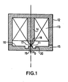
- Figure 1 is a sectional view of a resonator the microwave oscillator according to the invention.
- the magnetic circuit for an iron garnet and yttrium ball oscillator resonator 11, shown in FIG. 1, consists of a first cylindrical pole piece 12 comprising a coil 13 arranged around an axial core 14 and by a second cylindrical pole piece 15 with a flat bottom 16.
- the two cylindrical pole pieces 12, 15 are joined to one another in order to close the magnetic circuit, and the ball 11 of YIG is placed in an air gap 17 defined by a end 18 of the axial core 14 and of part 19 of the flat bottom 16 opposite said end 18.
- a groove 20 is arranged in the flat bottom 16 around said part 19 opposite of the end 18 of the axial core 14.
- the width of the groove 20 is between 1 and 2 times the width of the air gap 17 and the depth of said groove is of the order of the width of said air gap. More specifically, the Applicant has produced a magnetic circuit in accordance with the invention in which the air gap has a width of 1.8 mm and whose groove is 2.75 mm in width and 1.5 mm in depth. Furthermore, the Applicant has also observed a marked improvement in the linearity of the microwave source provided with the magnetic circuit according to the invention.
Landscapes
- Control Of Motors That Do Not Use Commutators (AREA)
- Inductance-Capacitance Distribution Constants And Capacitance-Resistance Oscillators (AREA)
Applications Claiming Priority (2)
| Application Number | Priority Date | Filing Date | Title |
|---|---|---|---|
| FR8219525A FR2536589A1 (fr) | 1982-11-22 | 1982-11-22 | Circuit magnetique pour resonateur d'oscillateur a bille de grenat de fer et d'yttrium |
| FR8219525 | 1982-11-22 |
Publications (2)
| Publication Number | Publication Date |
|---|---|
| EP0109714A1 true EP0109714A1 (de) | 1984-05-30 |
| EP0109714B1 EP0109714B1 (de) | 1986-02-12 |
Family
ID=9279391
Family Applications (1)
| Application Number | Title | Priority Date | Filing Date |
|---|---|---|---|
| EP83201627A Expired EP0109714B1 (de) | 1982-11-22 | 1983-11-15 | Magnetische Vorrichtung für einen YIG-Kugelresonator eines Oszillators |
Country Status (6)
| Country | Link |
|---|---|
| US (1) | US4516096A (de) |
| EP (1) | EP0109714B1 (de) |
| JP (1) | JPS59105701A (de) |
| CA (1) | CA1203585A (de) |
| DE (1) | DE3362131D1 (de) |
| FR (1) | FR2536589A1 (de) |
Cited By (1)
| Publication number | Priority date | Publication date | Assignee | Title |
|---|---|---|---|---|
| US5291163A (en) * | 1992-07-29 | 1994-03-01 | Hewlett-Packard Company | YIG sphere positioning apparatus |
Families Citing this family (3)
| Publication number | Priority date | Publication date | Assignee | Title |
|---|---|---|---|---|
| CA1266100A (en) * | 1985-07-09 | 1990-02-20 | Seigo Ito | Yig thin film microwave apparatus |
| DE3834984A1 (de) * | 1988-10-14 | 1990-04-19 | Leybold Ag | Einrichtung zur erzeugung von elektrisch geladenen und/oder ungeladenen teilchen |
| US5677652A (en) * | 1996-04-24 | 1997-10-14 | Verticom, Inc. | Microwave ferrite resonator with parallel permanent magnet bias |
Citations (4)
| Publication number | Priority date | Publication date | Assignee | Title |
|---|---|---|---|---|
| FR1208990A (fr) * | 1957-12-02 | 1960-02-26 | Philips Nv | Circulateur à guides d'ondes |
| US3085212A (en) * | 1961-04-17 | 1963-04-09 | Sperry Rand Corp | Tunable circulator |
| US3576503A (en) * | 1969-11-12 | 1971-04-27 | Hewlett Packard Co | Yig-tuned solid state oscillator |
| GB1360080A (en) * | 1971-12-22 | 1974-07-17 | Melnikov J A | Magnetic system |
Family Cites Families (1)
| Publication number | Priority date | Publication date | Assignee | Title |
|---|---|---|---|---|
| US4468643A (en) * | 1982-07-06 | 1984-08-28 | Varian Associates, Inc. | Magnetic circuit adjustable by tapered screws |
-
1982
- 1982-11-22 FR FR8219525A patent/FR2536589A1/fr active Granted
-
1983
- 1983-10-31 US US06/547,146 patent/US4516096A/en not_active Expired - Fee Related
- 1983-11-15 EP EP83201627A patent/EP0109714B1/de not_active Expired
- 1983-11-15 DE DE8383201627T patent/DE3362131D1/de not_active Expired
- 1983-11-17 CA CA000441372A patent/CA1203585A/en not_active Expired
- 1983-11-19 JP JP58217118A patent/JPS59105701A/ja active Granted
Patent Citations (4)
| Publication number | Priority date | Publication date | Assignee | Title |
|---|---|---|---|---|
| FR1208990A (fr) * | 1957-12-02 | 1960-02-26 | Philips Nv | Circulateur à guides d'ondes |
| US3085212A (en) * | 1961-04-17 | 1963-04-09 | Sperry Rand Corp | Tunable circulator |
| US3576503A (en) * | 1969-11-12 | 1971-04-27 | Hewlett Packard Co | Yig-tuned solid state oscillator |
| GB1360080A (en) * | 1971-12-22 | 1974-07-17 | Melnikov J A | Magnetic system |
Non-Patent Citations (2)
| Title |
|---|
| IEEE TRANSACTIONS ON MICROWAVE THEORY AND TECHNIQUES, vol. MTT-18, no. 4, avril 1970, pages 205-212, IEEE, New York, USA * |
| MICROWAVE JOURNAL, vol. 18, no. 9, septembre 1975, pages 33-35,50, Horizon House, Dedham; USA * |
Cited By (1)
| Publication number | Priority date | Publication date | Assignee | Title |
|---|---|---|---|---|
| US5291163A (en) * | 1992-07-29 | 1994-03-01 | Hewlett-Packard Company | YIG sphere positioning apparatus |
Also Published As
| Publication number | Publication date |
|---|---|
| JPS59105701A (ja) | 1984-06-19 |
| FR2536589B1 (de) | 1985-03-01 |
| DE3362131D1 (en) | 1986-03-27 |
| FR2536589A1 (fr) | 1984-05-25 |
| CA1203585A (en) | 1986-04-22 |
| EP0109714B1 (de) | 1986-02-12 |
| JPH0443441B2 (de) | 1992-07-16 |
| US4516096A (en) | 1985-05-07 |
Similar Documents
| Publication | Publication Date | Title |
|---|---|---|
| EP0407957B1 (de) | Wärmeabfuhrvorrichtung für Komponenten vom Typ SMD zur Montage auf Schaltplatten | |
| ES2035780B1 (es) | Conectador soldado para un cable coaxial apantallado. | |
| EP0612206A1 (de) | Elektrisches Masseverbindungssystem zwischen einer koaxialen Steckverbindung und der Platte einer hyperfrequenten Schaltung und elektrische Verbindungsvorrichtung für dieses System | |
| WO1996030773A1 (fr) | Capteur de courant electrique | |
| FR2739200A1 (fr) | Piece d'horlogerie comportant une antenne | |
| EP0138642A1 (de) | Mittels Dauermagneten und Solenoiden erzeugte ferromagnetische Struktur einer Ionenquelle | |
| EP0109714B1 (de) | Magnetische Vorrichtung für einen YIG-Kugelresonator eines Oszillators | |
| FR3019698A1 (fr) | Machine electrique equipee d'une tole de blindage | |
| EP0230819A1 (de) | Miniaturisiertes gyromagnetisches Gerät und dessen Zusammenbauverfahren | |
| FR2573934A1 (fr) | Dynamo pour vehicule | |
| FR2800167A1 (fr) | Dispositif pour la mesure d'un courant electrique et compteur d'electricite comprenant un tel dispositif | |
| EP0097087B1 (de) | Gehäuse mit Kunststoffkappe für Halbleiterbauelemente | |
| EP0794545B1 (de) | Vakuumschalter oder Lastschalter | |
| FR2564246A1 (fr) | Dispositif de fixation pour maintenir une plaquette de hall dans un champ magnetique | |
| US3072867A (en) | Internal magnet coaxial line device | |
| FR2842951A1 (fr) | Antenne a plaque de faible epaisseur | |
| EP0222445A1 (de) | Schaltung mit einem Mikrostreifenresonator | |
| FR2552271A1 (fr) | Dispositif de fixation d'une antenne active sur un vehicule | |
| FR2918243A1 (fr) | Circuit electronique comprenant un module de commande et un module hf s'etendant dans des plans differents | |
| FR2614150A1 (fr) | Oscillateur a resonateur dielectrique et accord electronique de frequence par varactor, notamment dans la gamme des 22 ghz | |
| EP0278300B1 (de) | Millimeter-Wellen-Generator mit hoher Stabilität für Frequenzsprungbetrieb | |
| CH677034A5 (en) | High current measuring sensor - includes magnetic field detector in air gap of magnetic circuit surrounding current carrying cable | |
| GB1216125A (en) | Bulk oscillators | |
| FR2672835A1 (fr) | Dispositif d'accouplement temporaire d'au moins deux organes. | |
| EP0329050A1 (de) | Elektronische Mikroschaltung |
Legal Events
| Date | Code | Title | Description |
|---|---|---|---|
| PUAI | Public reference made under article 153(3) epc to a published international application that has entered the european phase |
Free format text: ORIGINAL CODE: 0009012 |
|
| AK | Designated contracting states |
Designated state(s): DE FR GB SE |
|
| 17P | Request for examination filed |
Effective date: 19840725 |
|
| GRAA | (expected) grant |
Free format text: ORIGINAL CODE: 0009210 |
|
| AK | Designated contracting states |
Designated state(s): DE FR GB SE |
|
| REF | Corresponds to: |
Ref document number: 3362131 Country of ref document: DE Date of ref document: 19860327 |
|
| PLBE | No opposition filed within time limit |
Free format text: ORIGINAL CODE: 0009261 |
|
| STAA | Information on the status of an ep patent application or granted ep patent |
Free format text: STATUS: NO OPPOSITION FILED WITHIN TIME LIMIT |
|
| 26N | No opposition filed | ||
| REG | Reference to a national code |
Ref country code: FR Ref legal event code: CA |
|
| REG | Reference to a national code |
Ref country code: FR Ref legal event code: CD |
|
| PGFP | Annual fee paid to national office [announced via postgrant information from national office to epo] |
Ref country code: GB Payment date: 19911031 Year of fee payment: 9 |
|
| PGFP | Annual fee paid to national office [announced via postgrant information from national office to epo] |
Ref country code: FR Payment date: 19911118 Year of fee payment: 9 |
|
| PGFP | Annual fee paid to national office [announced via postgrant information from national office to epo] |
Ref country code: SE Payment date: 19911126 Year of fee payment: 9 |
|
| PGFP | Annual fee paid to national office [announced via postgrant information from national office to epo] |
Ref country code: DE Payment date: 19920127 Year of fee payment: 9 |
|
| PG25 | Lapsed in a contracting state [announced via postgrant information from national office to epo] |
Ref country code: GB Effective date: 19921115 |
|
| PG25 | Lapsed in a contracting state [announced via postgrant information from national office to epo] |
Ref country code: SE Effective date: 19921116 |
|
| GBPC | Gb: european patent ceased through non-payment of renewal fee |
Effective date: 19921115 |
|
| PG25 | Lapsed in a contracting state [announced via postgrant information from national office to epo] |
Ref country code: FR Effective date: 19930730 |
|
| PG25 | Lapsed in a contracting state [announced via postgrant information from national office to epo] |
Ref country code: DE Effective date: 19930803 |
|
| REG | Reference to a national code |
Ref country code: FR Ref legal event code: ST |
|
| EUG | Se: european patent has lapsed |
Ref document number: 83201627.3 Effective date: 19930610 |