EP0109732A1 - Palpeur pour le contrôle du fonctionnement d'un convoyeur d'accumulation - Google Patents
Palpeur pour le contrôle du fonctionnement d'un convoyeur d'accumulation Download PDFInfo
- Publication number
- EP0109732A1 EP0109732A1 EP83305282A EP83305282A EP0109732A1 EP 0109732 A1 EP0109732 A1 EP 0109732A1 EP 83305282 A EP83305282 A EP 83305282A EP 83305282 A EP83305282 A EP 83305282A EP 0109732 A1 EP0109732 A1 EP 0109732A1
- Authority
- EP
- European Patent Office
- Prior art keywords
- wheel
- sensor
- shaft
- propelling member
- wheels
- Prior art date
- Legal status (The legal status is an assumption and is not a legal conclusion. Google has not performed a legal analysis and makes no representation as to the accuracy of the status listed.)
- Ceased
Links
- 230000008859 change Effects 0.000 title description 5
- 230000007246 mechanism Effects 0.000 title description 2
- 238000009825 accumulation Methods 0.000 claims abstract description 16
- 230000004069 differentiation Effects 0.000 claims abstract 2
- 230000004044 response Effects 0.000 claims description 8
- 230000003247 decreasing effect Effects 0.000 claims description 2
- 238000011144 upstream manufacturing Methods 0.000 description 9
- 238000010276 construction Methods 0.000 description 7
- 230000000694 effects Effects 0.000 description 4
- 230000000284 resting effect Effects 0.000 description 3
- 230000006872 improvement Effects 0.000 description 2
- 230000002093 peripheral effect Effects 0.000 description 2
- 230000009467 reduction Effects 0.000 description 2
- 230000000712 assembly Effects 0.000 description 1
- 238000000429 assembly Methods 0.000 description 1
- 230000008901 benefit Effects 0.000 description 1
- 230000003111 delayed effect Effects 0.000 description 1
- 239000000428 dust Substances 0.000 description 1
- 230000007613 environmental effect Effects 0.000 description 1
- 238000004519 manufacturing process Methods 0.000 description 1
- 239000000463 material Substances 0.000 description 1
- 238000000034 method Methods 0.000 description 1
- 230000005012 migration Effects 0.000 description 1
- 238000013508 migration Methods 0.000 description 1
- 230000004048 modification Effects 0.000 description 1
- 238000012986 modification Methods 0.000 description 1
- 230000035945 sensitivity Effects 0.000 description 1
- 229920002994 synthetic fiber Polymers 0.000 description 1
- 230000007704 transition Effects 0.000 description 1
Images

Classifications
-
- B—PERFORMING OPERATIONS; TRANSPORTING
- B65—CONVEYING; PACKING; STORING; HANDLING THIN OR FILAMENTARY MATERIAL
- B65G—TRANSPORT OR STORAGE DEVICES, e.g. CONVEYORS FOR LOADING OR TIPPING, SHOP CONVEYOR SYSTEMS OR PNEUMATIC TUBE CONVEYORS
- B65G47/00—Article or material-handling devices associated with conveyors; Methods employing such devices
- B65G47/22—Devices influencing the relative position or the attitude of articles during transit by conveyors
- B65G47/26—Devices influencing the relative position or the attitude of articles during transit by conveyors arranging the articles, e.g. varying spacing between individual articles
- B65G47/261—Accumulating articles
-
- B—PERFORMING OPERATIONS; TRANSPORTING
- B65—CONVEYING; PACKING; STORING; HANDLING THIN OR FILAMENTARY MATERIAL
- B65G—TRANSPORT OR STORAGE DEVICES, e.g. CONVEYORS FOR LOADING OR TIPPING, SHOP CONVEYOR SYSTEMS OR PNEUMATIC TUBE CONVEYORS
- B65G2203/00—Indexing code relating to control or detection of the articles or the load carriers during conveying
- B65G2203/04—Detection means
- B65G2203/042—Sensors
Definitions
- This invention relates to conveyors and more particularly to the sensing mechanism for controlling the mode change of an accumulator conveyor.
- the forward motion of the articles can be initiated substantially simultaneously such that the discharge from the accumulator is basically that of a slugged line.
- a number of devices have been developed for sensing the presence and state of movement of the articles along the conveyor. These include article contacting sensors such as raised rollers or wheels, air jets which are interfered with by the continuing presence of an article and electric eyes and similar electric sensing means. All of these sensing devices respond to the presence of the article with the response being either immediate or in many cases delayed by any of several types of dampening means.
- the sensing units heretofore used have the drawback either of being very limited in the range of article weights capable of producing a response or being sensitive to environmental conditions such as moisture, dust and the like.
- the present invention is designed to provide a new, different and improved sensing means for controlling and automatically switching between transport and accumulation modes.
- a sensor for controlling mode shift between transport and accumulation of an accumulator conveyor having an article conveying surface comprised of transport rollers and a propelling member and means supporting said propelling member from beneath for vertical movement between transport roller engaged and disengaged positions is characterised in that said sensor has a shaft; a pair of wheels laterally spaced with respect to said conveying surface and mounted on said shaft; one of said wheels being in drive engagement with said propelling member and the other in drive engagement with one of said transport rollers; said shaft being mounted for pivotal movement about a vertical axis in response to differentation in angular velocity between said wheels; a one-way clutch between said shaft and said other wheel to permit said other wheel to remain stationary while said one wheel continues to rotate, and means connecting said sensor to said support means for transmitting pivotal movement of said sensor to said support means.
- an accumulator conveyor having article transport rollers and a driven, endless propelling member, a plurality of means supporting said propelling member, said means being arranged in groups positioned in tandem along said conveyor, said means being movable between a conveying position and an accumulation position, and a sensor for each of said groups responsive to article movement on said conveyor, is characterised in that said sensor has a shaft extending generally laterally of said conveyor, a first wheel mounted on one end thereof, a second wheel mounted on the other end thereof and a one-way clutch interconnecting said wheels, said first wheel being smaller than said second wheel, first means supporting said shaft intermediate its ends for pivotal movement about both a vertical axis and a horizontal axis, said first wheel being rotated by motion received from one of said article transport rollers, said second wheel being in driven contact with said propelling member, angular velocity differential of said wheels biasing said shaft to a position substantially normal to the axis of said conveyor when articles in contact with said transport roller are in motion, and said shaft being pivoted
- this invention provides sensing means responsive to motion. While some accumulator sensors incorporate signal or response delay capability so that the presence of an article in normal motion does not generate a mode change signal, the response is to article presence rather than article motion. This invention provides a sensor responsive to article motion by detecting the rate of rotation of the article supporting rollers.
- the invention provides a motion sensor consisting of a pair of spaced wheels interconnected by a one-way clutch.
- One wheel is in constant contact with and driven by the propellng member and the other wheel is in contact with and driven by one of the article supporting and transporting rollers.
- the roller contacting wheel is free to rotate in response to rotation of the roller but if the transport roller is held stationary by a stalled article or its angular velocity materially reduced due to slowing of the forward motion of the article, the wheel's rotation is similarly changed. Either situation will cause the sensor to shift the accumulator in the zone controlled by the sensor from transport to accumulation mode. At the same time, as soon as the article is once more free to move, the sensor will respond to the roller's motion and restore the accumulator to transport mode.
- the reaction of the sensor of this invention can be translated into mode shift control in any of several ways.
- upstream and downstream refer to the direction of movement of articles being transported.
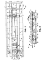
- the direction of article movement is indicated in Figure 2 by the arrow A and the direction of belt travel by the arrow B.
- the numeral lO identifies an accumulator having a pair of side frame members 11 interconnected by cross members 12.
- Forming the top surface of the accumulator and rotatably mounted at uniformly spaced intervals lengthwise thereof are carrier or transport rollers 13. These are supported by the side frame members 11. Beneath the rollers and supported on the cross members 12 are a pair of rails 14 defining a medial lane 15.
- Rotatably mounted between the rails 14 at uniformly spaced intervals are support rollers 16.
- the support rollers 6 support a propelling member 17.
- the support rollers 16 are arranged in groups with all the rollers forming a group being interconnected by an auxiliary or secondary driving member or belt 18.
- the belt 18 is trained over a terminal roller 19 which is of uniform diameter and smaller than the support rollers 16.
- the number of support rollers assigned to a group is determined by the average length of the articles to be moved on the conveyor.
- Each group of support rollers connected by a common secondary belt 18 constitutes a zone with the zones being arranged in tandem along the length of the conveyor.
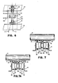
- Each of the support rollers 16 is symmetrical about its midpoint having a central channel 30 to receive the guide rib of the primary propelling member 17 ( Figures 7 and 7A).
- On each side of the channel 30 is an inner portion 31 separated from the channel 30 by a flange 36.
- Outwardly of the inner portions 31 are the outer portions 32.
- the outer portions 32 are of greater diameter than the inner portions 31 with the two portions being connected by a ramp 33.
- the inner and outer portions provide the supports for the auxiliary belt 18 with the ramps 33 providing the guide to facilitate lateral movement of the belt from one portion to another.
- the auxiliary belt is on the outer portion 32, it is positioned between the propelling member and the support rollers whereby it is positively driven by the propellng member 17.
- the position of the auxiliary belt 18 is controlled by a sensor assembly 40.
- a separate sensor assembly is provided for each zone with the sensor for one zone being located adjacent the discharge end of the next downstream zone. Thus, the sensors do not control the mode of the zone in which they are located.
- Each sensor has a pair of wheels 41 and 42 mounted on a commmon axle or shaft 43 ( Figures 3 and 4).
- the axle is mounted in an elongated housing 44 which is pivotally supported intermediate its ends, preferably at midpoint between the ends, by a post 45.
- Pins 46 provide a pivotal attachment of the housing 44 to a yoke 50 at the top of the post.
- the wheel 41 is mounted on one end of the shaft 43 and so attached that the shaft is forced to rotate by the wheel.
- the wheel 42 is connected to the shaft 43 by a one-way clutch 47.
- the wheel 41 contacts the primary propelling member 17 while the wheel 42 contacts a transport roller 13a.
- the arrangement of the clutch 47 is such that the wheel 42 can be held stationary by the transport or sensor roller 13a while the wheel 41 and the shaft 43 can continue to rotate under the driving force of the propelling member 17.
- the pivot post 45 is supported by a bearing block 51. Below the bearing block a terminal block 53 is secured to the bottom of the post. This arrangement is made necessary because the pivot post 45 is urged upwardly by a spring 54 surrounding the post between the top of the bearing block 51 and a bearing 55 between the upper end of the spring and the yoke 50.
- the bearing bock 51 is bolted to the bottom surface of a support member 57 which in turn is supported by the rails 14.
- the bearing block has a boss 52 to support the shaft of the post.
- the wheel 41 in contact with the belt 17 is approximately ten percent larger than the wheel 42 contacting the transport roller 13a.
- Both wheels 41 and 42 are preferably provided with a tyre of a suitable synthetic material to provide the necessary frictional contact between the wheels and the roller or belt.
- the terminal block 53 secured to the bottom end of the pivot post mounts one end of an actuator rod 60.
- the actuator rod extends upstream of the conveyor from the sensor to a position upstream of the downstream one 16a of the support rollers 16 of the next upstream zone ( Figures 1 and 4).
- the end of the actuator rod being adjacent the support roller 16a is seated in one of a pair of pockets 61 in the downstream face of the bearing block 51 of the adjacent upstream sensor assembly 40.
- the rod Adjacent the bearing block in which the end of the rod 60 is supported, the rod has a pair of laterally spaced upstanding fingers 62 which bracket the auxiliary belt 18 immediately above it.
- the sensor 40 in the affected zone does not change its vertical position since its vertical position is the result of the resilient bias of the spring 54.
- contact between the sensor 40 and both the propelling member 17 and the sensor roller 13a remains constant.
- This bias is not enough to lift the sensor roller 13a when no article is resting on it.
- the sensor 40 will not pivot because the roller 13a will continue to rotate under the drive of the propelling member 17 until an article in contact with it forces it to either slow or stop. Only then will the sensor react.
- This eliminates sequential shifting to accumulation mode. Any other arrangement would trigger a cascading effect of shift to accumulation mode upstream of the sensor even though there was no reason for such a shift. This effect would occur even though the entire upstream portion of the accumulator was vacant.
- the pressure exerted by the spring 54 is such that the sensor roller 13a is easily held stationary by even a small stationary article resting on it, even though contact between it and the propelling member is maintained.
- Article movement will be reinitiated in the downstream zone when its auxiliary belt 18 has been caused by any suitable means to shift to drive position.
- the sensor assembly in that zone wil be caused to shift to drive position because the wheel 42 will accelerate until it again exceeds that of the wheel 41.
- This restores transport in the zone affected by the sensor assembly by causing the auxiliary belt to once again travel up the ramps onto the outer portions of the support rollers.
- the end of the rod 60 being trapped in one of the pockets 61 limits the pivotal movement of the sensor.
- the sensor is held in substantial alignment with the transport rollers (line C, Figure 6) when the accumulator is in transport mode.
- the sensor shifts to a small angular position (line D, Figure 6) when in accumulation mode.
- the actual arc of movement is small and engagement between the sensor and the transport roller is maintained at all times.
- the force necessary to cause the auxiliary belt 18 to initiate its movement from one portion of the support roller to another is small because all the sensor has to do is to apply a very small lateral force against the belt ⁇ to initiate lateral movement.
- the rotation of the support rollers 16 and the effect of the ramps 33 provide both the guidance and most of the energy necessary to cause the belt to make the transition in either direction.
- the support rollers 16 are symmetrical about their midpoint but, in any one zone, mount an auxiliary belt 18 only on one side. It will be noted from Figure 1 that the auxiliary belts in adjacent zones are installed on opposite sides at the centreline of the support rollers. By so doing, the propelling member 17 is alternately supported on opposite sides. This assures accurate tracking of the propelling member. Thus, the need of double belts and the problems that such would create in the necessity to synchronize their movement is eliminated.
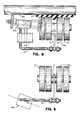
- the invention can be used without the satellite or auxiliary belt as a means of shifting conveyors equipped with the eccentric type of propelling member support to effect engagement and disengagement of the propelling member by stopping rotation of the support rollers with their flattened segments engaging the belt.
- This construction of support roller and its method of raising and lowering the belt is described in US-A-3 854 576.
- the application of the invention to such a conveyor is shown in Figures 8 and'9.
Landscapes
- Engineering & Computer Science (AREA)
- Mechanical Engineering (AREA)
- Control Of Conveyors (AREA)
- Rollers For Roller Conveyors For Transfer (AREA)
- Attitude Control For Articles On Conveyors (AREA)
Applications Claiming Priority (2)
| Application Number | Priority Date | Filing Date | Title |
|---|---|---|---|
| US06/419,149 US4473148A (en) | 1982-09-17 | 1982-09-17 | Motion sensor for motion sensing accumulator |
| US419149 | 1982-09-17 |
Publications (1)
| Publication Number | Publication Date |
|---|---|
| EP0109732A1 true EP0109732A1 (fr) | 1984-05-30 |
Family
ID=23660994
Family Applications (1)
| Application Number | Title | Priority Date | Filing Date |
|---|---|---|---|
| EP83305282A Ceased EP0109732A1 (fr) | 1982-09-17 | 1983-09-09 | Palpeur pour le contrôle du fonctionnement d'un convoyeur d'accumulation |
Country Status (5)
| Country | Link |
|---|---|
| US (1) | US4473148A (fr) |
| EP (1) | EP0109732A1 (fr) |
| JP (1) | JPS5982218A (fr) |
| AU (1) | AU1531583A (fr) |
| CA (1) | CA1200224A (fr) |
Cited By (1)
| Publication number | Priority date | Publication date | Assignee | Title |
|---|---|---|---|---|
| ES2605426A1 (es) * | 2016-09-09 | 2017-03-14 | Mecalux, S.A. | Sistema transportador de cargas, estructura modular y una instalación de transporte de cargas |
Families Citing this family (8)
| Publication number | Priority date | Publication date | Assignee | Title |
|---|---|---|---|---|
| JPS61150320U (fr) * | 1985-03-08 | 1986-09-17 | ||
| JPS61150322U (fr) * | 1985-03-08 | 1986-09-17 | ||
| US5810154A (en) * | 1996-06-11 | 1998-09-22 | Mannesmann Dematic Rapistan Corp. | Low actuation force article sensor for conveyor |
| US6478142B2 (en) * | 1998-12-09 | 2002-11-12 | Rapistan Systems Advertising Corp. | Contact assembly for accumulation conveyors |
| US6390286B1 (en) * | 1999-01-08 | 2002-05-21 | Rapistan Systems Advertising Corp. | Belt driven roller conveyor |
| US6343489B1 (en) * | 1999-12-20 | 2002-02-05 | Visteon Global Technologies Inc. | Bending rail band guide |
| US6685005B2 (en) * | 2001-08-10 | 2004-02-03 | Ermanco Incorporated | Skewed-roller belt drive for belt-driven roller conveyor |
| DE20207498U1 (de) * | 2002-05-14 | 2003-09-25 | Transnorm System GmbH, 31177 Harsum | Rollenförderer |
Citations (2)
| Publication number | Priority date | Publication date | Assignee | Title |
|---|---|---|---|---|
| US3420356A (en) * | 1967-07-12 | 1969-01-07 | Rapistan Inc | Low pressure accumulator |
| US3854576A (en) * | 1973-06-27 | 1974-12-17 | Rapistan Inc | Eccentric wheel accumulators |
Family Cites Families (5)
| Publication number | Priority date | Publication date | Assignee | Title |
|---|---|---|---|---|
| US4091916A (en) * | 1976-10-08 | 1978-05-30 | W & H Conveyor Systems, Inc. | Apparatus for driving individual rollers of a power conveyer |
| US4273239A (en) * | 1979-04-23 | 1981-06-16 | Contran Conveyors & Systems, Inc. | Zero pressure accumulator and braking apparatus therefor |
| US4353458A (en) * | 1980-05-09 | 1982-10-12 | Lear Siegler, Inc. | Belt supports for accumulators |
| US4361224A (en) * | 1980-05-19 | 1982-11-30 | Lear Siegler, Inc. | Roller motion sensing accumulator |
| US4361225A (en) * | 1980-09-18 | 1982-11-30 | Lear Siegler, Inc. | Actuator belt accumulator |
-
1982
- 1982-09-17 US US06/419,149 patent/US4473148A/en not_active Expired - Fee Related
-
1983
- 1983-06-02 AU AU15315/83A patent/AU1531583A/en not_active Abandoned
- 1983-06-06 CA CA000429773A patent/CA1200224A/fr not_active Expired
- 1983-09-09 EP EP83305282A patent/EP0109732A1/fr not_active Ceased
- 1983-09-16 JP JP58169508A patent/JPS5982218A/ja active Pending
Patent Citations (2)
| Publication number | Priority date | Publication date | Assignee | Title |
|---|---|---|---|---|
| US3420356A (en) * | 1967-07-12 | 1969-01-07 | Rapistan Inc | Low pressure accumulator |
| US3854576A (en) * | 1973-06-27 | 1974-12-17 | Rapistan Inc | Eccentric wheel accumulators |
Cited By (1)
| Publication number | Priority date | Publication date | Assignee | Title |
|---|---|---|---|---|
| ES2605426A1 (es) * | 2016-09-09 | 2017-03-14 | Mecalux, S.A. | Sistema transportador de cargas, estructura modular y una instalación de transporte de cargas |
Also Published As
| Publication number | Publication date |
|---|---|
| CA1200224A (fr) | 1986-02-04 |
| US4473148A (en) | 1984-09-25 |
| AU1531583A (en) | 1984-03-22 |
| JPS5982218A (ja) | 1984-05-12 |
Similar Documents
| Publication | Publication Date | Title |
|---|---|---|
| US3730330A (en) | Sensor locking accumulator | |
| US6199677B1 (en) | Spiral conveyor apparatus with automatic flow control | |
| US5957265A (en) | Conveyor with bridge roller assembly | |
| US4473148A (en) | Motion sensor for motion sensing accumulator | |
| EP0040949B1 (fr) | Convoyeurs à accumulation | |
| US4328889A (en) | Conveyor means | |
| US3420356A (en) | Low pressure accumulator | |
| US5806661A (en) | Sensor for detecting lightweight objects on a conveyor | |
| US5014625A (en) | Linear motor driven trolley conveyor | |
| US4361225A (en) | Actuator belt accumulator | |
| US3967718A (en) | Live roller conveyor | |
| US3156345A (en) | Motor powered accumulating conveyor | |
| WO1997031843A1 (fr) | Detecteur a rouleaux pour detecter des objets legers | |
| WO1997031843A9 (fr) | Detecteur a rouleaux pour detecter des objets legers | |
| US3980172A (en) | Low line pressure accumulator | |
| NL8103958A (nl) | Transportinrichting. | |
| US3877565A (en) | Pressure free article conveyor | |
| US4353458A (en) | Belt supports for accumulators | |
| US6237755B1 (en) | Chain drive with adjustable friction | |
| JPH09278152A (ja) | ベルトコンベヤのベルト蛇行矯正装置 | |
| US3877566A (en) | Chain conveyor of swing-stirrup type | |
| KR20020041061A (ko) | 양방향 벨트 콘베이어용 사행자동조정장치 | |
| WO1997006081A1 (fr) | Galet guide de convoyeur | |
| SU1411245A1 (ru) | Устройство дл улавливани грузонесущей ленты конвейера | |
| AU704170B2 (en) | A training idler |
Legal Events
| Date | Code | Title | Description |
|---|---|---|---|
| PUAI | Public reference made under article 153(3) epc to a published international application that has entered the european phase |
Free format text: ORIGINAL CODE: 0009012 |
|
| AK | Designated contracting states |
Designated state(s): DE GB NL |
|
| 17P | Request for examination filed |
Effective date: 19840626 |
|
| STAA | Information on the status of an ep patent application or granted ep patent |
Free format text: STATUS: THE APPLICATION HAS BEEN REFUSED |
|
| 18R | Application refused |
Effective date: 19860804 |
|
| RIN1 | Information on inventor provided before grant (corrected) |
Inventor name: SAUR, CHARLES WILLIAM |