EP0109862A1 - Procédé et appareil pour insérer des objets tubulaires dans des récipients - Google Patents
Procédé et appareil pour insérer des objets tubulaires dans des récipients Download PDFInfo
- Publication number
- EP0109862A1 EP0109862A1 EP83307164A EP83307164A EP0109862A1 EP 0109862 A1 EP0109862 A1 EP 0109862A1 EP 83307164 A EP83307164 A EP 83307164A EP 83307164 A EP83307164 A EP 83307164A EP 0109862 A1 EP0109862 A1 EP 0109862A1
- Authority
- EP
- European Patent Office
- Prior art keywords
- tubular article
- container
- work station
- containers
- tube
- Prior art date
- Legal status (The legal status is an assumption and is not a legal conclusion. Google has not performed a legal analysis and makes no representation as to the accuracy of the status listed.)
- Granted
Links
- 238000000034 method Methods 0.000 title claims description 15
- 239000004033 plastic Substances 0.000 claims abstract description 10
- 229920003023 plastic Polymers 0.000 claims abstract description 10
- 230000005484 gravity Effects 0.000 claims abstract description 6
- 239000012528 membrane Substances 0.000 claims description 6
- 238000001816 cooling Methods 0.000 claims description 2
- 230000000452 restraining effect Effects 0.000 claims 5
- 235000013361 beverage Nutrition 0.000 abstract description 4
- 238000003780 insertion Methods 0.000 description 10
- 230000037431 insertion Effects 0.000 description 10
- 239000006188 syrup Substances 0.000 description 8
- 235000020357 syrup Nutrition 0.000 description 8
- 230000007246 mechanism Effects 0.000 description 3
- 239000000203 mixture Substances 0.000 description 3
- -1 polyethylene Polymers 0.000 description 3
- 239000004698 Polyethylene Substances 0.000 description 2
- 229920000573 polyethylene Polymers 0.000 description 2
- 238000007789 sealing Methods 0.000 description 2
- 239000004743 Polypropylene Substances 0.000 description 1
- 238000010924 continuous production Methods 0.000 description 1
- 239000011888 foil Substances 0.000 description 1
- 235000015243 ice cream Nutrition 0.000 description 1
- 230000003993 interaction Effects 0.000 description 1
- 239000007788 liquid Substances 0.000 description 1
- 238000004519 manufacturing process Methods 0.000 description 1
- 239000000463 material Substances 0.000 description 1
- 239000002184 metal Substances 0.000 description 1
- 239000002991 molded plastic Substances 0.000 description 1
- 229920001155 polypropylene Polymers 0.000 description 1
Images


Classifications
-
- B—PERFORMING OPERATIONS; TRANSPORTING
- B23—MACHINE TOOLS; METAL-WORKING NOT OTHERWISE PROVIDED FOR
- B23P—METAL-WORKING NOT OTHERWISE PROVIDED FOR; COMBINED OPERATIONS; UNIVERSAL MACHINE TOOLS
- B23P19/00—Machines for simply fitting together or separating metal parts or objects, or metal and non-metal parts, whether or not involving some deformation; Tools or devices therefor so far as not provided for in other classes
- B23P19/02—Machines for simply fitting together or separating metal parts or objects, or metal and non-metal parts, whether or not involving some deformation; Tools or devices therefor so far as not provided for in other classes for connecting objects by press fit or for detaching same
- B23P19/022—Extracting or inserting relatively long parts
-
- B—PERFORMING OPERATIONS; TRANSPORTING
- B31—MAKING ARTICLES OF PAPER, CARDBOARD OR MATERIAL WORKED IN A MANNER ANALOGOUS TO PAPER; WORKING PAPER, CARDBOARD OR MATERIAL WORKED IN A MANNER ANALOGOUS TO PAPER
- B31B—MAKING CONTAINERS OF PAPER, CARDBOARD OR MATERIAL WORKED IN A MANNER ANALOGOUS TO PAPER
- B31B50/00—Making rigid or semi-rigid containers, e.g. boxes or cartons
- B31B50/74—Auxiliary operations
- B31B50/81—Forming or attaching accessories, e.g. opening devices, closures or tear strings
- B31B50/84—Forming or attaching means for filling or dispensing contents, e.g. valves or spouts
Definitions
- the present invention relates to a tubular article handling machine and, more specifically but not exclusively, to a machine for sequentially feeding a plurality of flow rate control tubes into syrup packages for use in gravity flow post-mix beverage dispensers.
- Disposable packages for dispensing liquids with a controlled rate of flow have been developed for gravity flow post-mix beverage.dispensers.
- An example of such a package is disclosed in U.S. Patent 4,216,885 to Sedam, which is assigned to the same assignee as the present invention.
- This disposable package includes a thin-wall plastic container with a closed end and an opposed.discharge opening.
- the flow rate control tube is positioned in the container with one open end extending through the closed end of the container and the opposite open end disposed at a predetermined distance within the container from the position of the discharge opening.
- the discharge opening of the container is sealed by a removable cap and a rupturable membrane.
- the container and the flow rate control tube are normally manufactured separately, and must be assembled to form a complete package.
- the flow rate control tube may be automatically inserted into the container so as to eliminate manual handling of the individual components of the disposable package while, at the same time, providing an expedient, efficient and 'rapid means for assembling the disposable package. It would also be desirable to be able to manufacture the package in a continuous process with the-blow- molded plastic containers.
- the aforementioned prior art- devices include reciprocating pusher members which engage or impact the ends of tubular articles and launch them into associated guide devices which direct them to a container or work station.
- These guide devices are bulky and require precise alignment with associated components.
- some type of stop means is required at the work station for the tube to achieve proper positioning in a container or the like.
- the present invention provides an apparatus for automatically inserting a tubular article within each of a sequence of containers at the same predetermined positions therein, comprising:
- the invention provides a method of automatically inserting a tubular article within each of a sequence of plastic containers through an aperture in the bottom thereof to the same predetermined position within each said container, comprising the steps of:
- the invention provides an apparatus for automatically inserting a flow-rate control tube into each of a sequence of containers through the bottom surfaces thereof, said apparatus comprising:
- a preferred form of the invention comprises an apparatus for sequentially feeding a plurality of flow -rate control tubes into containers which are subsequently used in gravity flow post-mix beverage dispensers.
- a vertical feed hopper is provided which contains a plurality of flow rate control tubes, the hopper being funnel-shaped to guide the tubes into a long, narrow trough or feeder chute positioned below or at the bottom of the hopper for receiving the tubes single file.
- the hopper is equipped with a motor-driven reciprocating paddle disposed therein to assist the flow of tubes into said trough.
- a rotating brush is further provided juxtapositioned to the narrow trough to drive and direct the flow of tubes in the trough vertically downward to the dispensing station.
- a reciprocating pusher member enters the lowermost tubes and carries them, one at a time, horizontally from the dispensing station at the bottom of the .chute into an.aperture in a pliable plastic container which is transported along a conveyor transversely to the direction of the movement of the pusher member.
- the aperture in the container is slightly smaller than the outer diameter of the tube, but pliable because of the softened state, permitting insertion into the container.
- the tube is initially restrained by a rubber wiper in a guide aperture and will slide onto the pusher member before it moves longitudinally to ensure accurate insertion into the container aperture and precise positioning within the container.
- Automatic control systems are provided for synchronizing the operation of the machine.
- the configuration of the present apparatus provides for automatic insertion of the respective tubes into succeeding syrup containers, thereby providing a method which is completely automatic for assemblying a syrup package.
- FIG. 1 there is illustrated a disposable syrup package 40 to be assembled by the apparatus of the present invention.
- the disposable package 40 includes a plastic bottle or container 42 having thin sidewalls, a closed end 44 and an open end 46 defining a discharge opening of the disposable package.
- the open end 46 is provided with a closure member 50.
- a rupturable membrane, such as a metal foil 52, is secured across the discharge opening at the container end 46.
- a flow rate control tube 1.3 to be automatically inserted by the machine of Figure 2, to be described hereinafter, is permanently secured at a predetermined position within container 42 and has an open end 13A positioned at a predetermined distance above the discharge opening defined by open end 46 of the container.
- Tube 13 has an opposite open end 13B which extends through an aperture in the end portion 44 of the container 42. End portion 13B of tube 13 is disposed within the confines of recess 42A defined by annular skirt member 53 of plastic or other suitable material which is secured to the end of container 42, or the skirt may be formed as part of. the container 42.
- Tube 13 of container 42 is automatically inserted therein by the apparatus of Figure 2 as the containers are sequentially moved by a conveyor.
- Plastic containers 42 may be fabricated in any suitable manner, but are preferably blow molded from polyethylene, polypropylene or polyethylene teraphthalate with an aperture 42B in the closed end 42.
- Aperture 42B is of slightly smaller diameter than tube 13, as initially blow molded.
- tube 13 is force-fit therein when container 42 is in a softened plastic state.
- aperture 42B. is pliable in this state, and will easily flex as a tube 13 is inserted therein, and will also shrink around tube 13 to seal the same therein as container 42 cools and completely solidifies. The-advantages of this will become more readily apparent with reference to the operation of the apparatus of Figures 2 to 5.
- a hopper 10 having a long, narrow trough 12 at the bottom.
- a supply of tubes 13 is provided in the hopper 10 which are channeled into the trough 12, so as to provide a single file verticle arrangement of the tubes therein.
- the hopper is equipped with a reciprocating paddle 14 driven by a motor 15.
- the reciprocating rotary motion of the paddle just above the opening to the trough 12, ensures a constant and smooth flowing supply of tubes to the narrow trough 12.
- a rotating brush 16 Positioned adjacent to the narrow trough 12 is a rotating brush 16 which drives and directs the flow of the tubes 13 in the trough 12 through a window 17 in the side of the trough.
- the brush 16 is driven by a motor 18.
- a push rod 19 is provided which pushes the lowermost tube in slot 12A of trough 12 horizontally from the vertical stack into an associated container in response to appropriate drive signals, the operation of which is more fully discussed below.
- the tube 13 slides onto the push rod 19 to ensure proper insertion into the container opening before moving longitudinally. That is, the tube is partially restrained from longitudinal movement by suitable means, to be discussed in connection with Figures .4 and 5, until the rod 19 moves into the tube to support the same.
- the push rod 19 is provided with a disc 20 at its rear portion which activates a microswitch 21 at the completion of the insertion of the tube 13 into the container (not shown).
- the disc 20 activates the microswitch 21, which causes the push rod 19 to reverse, thus allowing for the next tube to drop to the lowermost portion of the trough 12 in front of the push rod 19, thus completing the cycle.
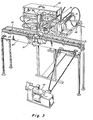
- FIG. 3 there is illustrated the tube inserting mechanism of Figure 2, mounted within a support frame and in combination with a conveyor mechanism for transporting the containers into which the tubes are to be inserted.
- the tubes 13 are placed in the hopper 10 which is provided with a cover 22, with.the.hopper terminating as a long, narrow trough 12 at the bottommost part thereof, as described hereinbefore.
- The. hopper is equipped with a reciprocating motor-driven paddle 14 (Fig. 2)for maintaining a constant and smooth supply of tubes to the trough 12.
- the narrow trough 12 is operatively associated with the rotating brush 16 for assisting the downward movement of tubes 13 in the trough by engaging the tubes through the window or opening 17.
- the brush is driven by motor 18.
- a conveyor 24 is located in front of the lowermost portion of the trough or chute 12, and conveys the containers 42, into which the tubes 13 are to be inserted.
- a limit switch 27 is actuated, which causes the conveyor to stop and an air piston- driven retaining clamp.28 to come down on the container.
- the retainer clamp 28 moves down, it actuates a limit switch 29 mechanically coupled thereto, which activates an air valve 30, which controls air cylinder 31.
- the air cylinder operates the push rod 19, which picks up and carries a tube from the bottom of the narrow trough 12 and inserts it into the bottom aperture 42A of the container which is being held in position by the clamp 28.
- a plate 32 fitted with a rubber wiper 32A in a hole 32B, is mounted between the narrow trough 12 and the container.
- the purpose of the wiper 32A (illustrated in Figures 4 and 5, described hereinafter) is to ensure that the tube is not pushed out ahead of the push rod, but must slide onto the push rod to ensure proper insertion into the container opening.
- the disc 20, mounted on the push rod 19, activates the microswitch 21, as discussed above, which reverses the push,rod 19 while, at the same time, the clamp 18 rises to release the -container. As the clamp 18 rises, it activates microswitch 29 which restarts the conveyor, bringing the next successive container into position for the next phase of the operation.
- FIG. 4 is an enlarged view of guide plate 32 of Figure 3, illustrating an enlarged aperture 32B therethrough and a flexible rubber wiper 32A disposed within aperture 32B.
- Wiper 32A seen through opening 32B, is annular in shape with a central aperture 32C of a slightly smaller diameter than the outside diameter of tubes 13. Wiper 32A may be secured within aperture 32B by any suitable means.
- push rod 1.9 may have a reduced diameter pick-up portion 19B of slightly less external diameter than the inside diameter of tube 13. This permits pick-up portion 19B to be inserted within tube 13, to carry the same to the desired position within container 42 until the push rod 19 is withdrawn.
- Push rod 19 has a shoulder 19A, which will engage the rear end of tube 13 in Figure 5 as push rod 19 moves from right to left in that Figure. When this occurs, tube 13 will be pushed entirely through wiper 32A into aperture 42A, and accurately located in container 42 as the forward stroke of push rod 19 is completed. Push rod 19 may then be withdrawn, leaving tube 13 within container 42 and aperture 42A in the desired position by virtue of the force fit in aperture 42A and the cooling of the warm container 42, which causes some subsequent shrinking and sealing of the container about the tube 13.
- the wiper 32A having a central aperture 32C of a slightly smaller diameter than the outside diameter of tube 13, deforms as it initially engages tube 13, creating a frictional drag on the surface thereof. Accordingly, tube 13 is at least partially restrained by wiper 32A until pick-up portion 19B of push rod 19 is fully inserted and shoulder 19A engages the rear end of tube 13. It can be seen that with the combination of the rod structure 19 and the flexible wiper 32A in Figure 5, that tube 13 is accurately carried into container 42 through aperture 42A, and is precisely located therein as a function of the forward stroke distance of reciprocating push rod 19. Since this forward stroke distance is always essentially the same, tubes 13 may be accurately disposed in the same desired positions within container 42. This is particularly important to the proper operation of the flow rate control tube in a syrup package in that the distance of the open end of tube 13B within the container with respect to the discharge opening thereof, may be critical to the proper operation of the package.
- the wiper 32A could have other configurations than the annular shape of Figures 4 and 5, if desired.
- this annular configuration provides a symmetric guide means, and, at the same time, applies an appropriate amount of drag on tube 13 to restrain its movement until pick-up portion 19B of rod 19 can be fully inserted therein.
- shoulder 19A of rod 19 could be a disk or flange on a rod having the same external diameter along its entire longitudinal length as the diameter of pick-up portion 19B, if desired.
Landscapes
- Engineering & Computer Science (AREA)
- Mechanical Engineering (AREA)
- Supplying Of Containers To The Packaging Station (AREA)
- Auxiliary Devices For And Details Of Packaging Control (AREA)
- Containers And Packaging Bodies Having A Special Means To Remove Contents (AREA)
- Packging For Living Organisms, Food Or Medicinal Products That Are Sensitive To Environmental Conditiond (AREA)
- Container Filling Or Packaging Operations (AREA)
- Feeding Of Articles To Conveyors (AREA)
- Branching, Merging, And Special Transfer Between Conveyors (AREA)
Applications Claiming Priority (2)
| Application Number | Priority Date | Filing Date | Title |
|---|---|---|---|
| US06/444,358 US4438061A (en) | 1982-11-23 | 1982-11-23 | Tube inserting machine |
| US444358 | 1982-11-23 |
Publications (2)
| Publication Number | Publication Date |
|---|---|
| EP0109862A1 true EP0109862A1 (fr) | 1984-05-30 |
| EP0109862B1 EP0109862B1 (fr) | 1987-05-27 |
Family
ID=23764570
Family Applications (1)
| Application Number | Title | Priority Date | Filing Date |
|---|---|---|---|
| EP83307164A Expired EP0109862B1 (fr) | 1982-11-23 | 1983-11-23 | Procédé et appareil pour insérer des objets tubulaires dans des récipients |
Country Status (10)
| Country | Link |
|---|---|
| US (1) | US4438061A (fr) |
| EP (1) | EP0109862B1 (fr) |
| JP (1) | JPS59103824A (fr) |
| AU (1) | AU561912B2 (fr) |
| BR (1) | BR8306274A (fr) |
| CA (1) | CA1215527A (fr) |
| DE (1) | DE3371755D1 (fr) |
| ES (1) | ES525657A0 (fr) |
| MX (1) | MX161195A (fr) |
| ZA (1) | ZA836459B (fr) |
Families Citing this family (5)
| Publication number | Priority date | Publication date | Assignee | Title |
|---|---|---|---|---|
| AU581655B2 (en) * | 1984-06-21 | 1989-03-02 | Coca-Cola Company, The | Integral vent tube |
| WO2008091706A1 (fr) * | 2007-01-25 | 2008-07-31 | Radio Robots Llc | Système contrôlé à distance et procédé pour préparer une boisson ou un produit alimentaire définis par un utilisateur |
| CN106078137B (zh) * | 2016-07-08 | 2017-11-17 | 中信重工机械股份有限公司 | 一种装配重型单作用油缸柱塞的下压平衡装置及方法 |
| CN106240955A (zh) * | 2016-08-31 | 2016-12-21 | 贵州苗仁堂生物医药科技有限责任公司 | 自动插管结构 |
| CN111744733B (zh) * | 2019-03-21 | 2022-04-19 | 桐乡三元电机科技有限公司 | 一种用于电机加工的浇浸设备出料机构 |
Citations (11)
| Publication number | Priority date | Publication date | Assignee | Title |
|---|---|---|---|---|
| US1039756A (en) * | 1912-04-13 | 1912-10-01 | William A Kirkpatrick | Dispensing-container. |
| US2251489A (en) * | 1939-03-06 | 1941-08-05 | Koziel Ignacy | Dispenser for elongated articles |
| GB789766A (en) * | 1955-11-08 | 1958-01-29 | Stanley Frank Rabin | Improvements in or relating to drinking straw and method and machine for making the same |
| US2971677A (en) * | 1957-08-26 | 1961-02-14 | Edgar F Ardell | Feeding device |
| US3019575A (en) * | 1959-02-13 | 1962-02-06 | Walter G Charley | Apparatus for inserting straws or the like |
| GB922663A (en) * | 1960-04-11 | 1963-04-03 | Safe T Pacific Baking Company | Improvements in drinking straws and methods of manufacturing such straws |
| US3438527A (en) * | 1967-08-17 | 1969-04-15 | Elton Berry Gamblin Jr | Drinking straws |
| US3740821A (en) * | 1971-11-05 | 1973-06-26 | Big Drum Inc | Method for assembling confection serving containers of the push up type |
| US4134247A (en) * | 1975-02-19 | 1979-01-16 | Sather Kenneth E | Method and apparatus for providing containers with straws |
| US4216885A (en) * | 1978-10-20 | 1980-08-12 | The Coca-Cola Company | Disposable package for dispensing liquids with a controlled rate of flow |
| EP0022595A1 (fr) * | 1979-07-11 | 1981-01-21 | Ab Tetra Pak | Machine à emballer des articles allongés dans un film en matière plastique |
Family Cites Families (7)
| Publication number | Priority date | Publication date | Assignee | Title |
|---|---|---|---|---|
| US2953997A (en) | 1956-03-16 | 1960-09-27 | Glass Robert Taylor | Confection machine |
| US3135993A (en) | 1959-10-08 | 1964-06-09 | Brunswick Corp | Molding and assembling apparatus and method |
| US3380118A (en) | 1965-07-01 | 1968-04-30 | Rapid Tool & Mfg Company Inc | Apparatus for making composite articles |
| US3519707A (en) | 1968-05-09 | 1970-07-07 | Ideal Ind | Method of making electrical connectors |
| US3776673A (en) | 1969-04-07 | 1973-12-04 | Sanford Res Co | Apparatus for securing nib in plastic writing instrument |
| US3632245A (en) | 1970-05-13 | 1972-01-04 | Vroman Foods Inc | Apparatus for the production of frozen confections |
| US4181695A (en) | 1978-01-09 | 1980-01-01 | Rickert Glenn E | Embedded body in soap |
-
1982
- 1982-11-23 US US06/444,358 patent/US4438061A/en not_active Expired - Fee Related
-
1983
- 1983-08-30 AU AU18535/83A patent/AU561912B2/en not_active Ceased
- 1983-08-30 CA CA000435661A patent/CA1215527A/fr not_active Expired
- 1983-08-31 ZA ZA836459A patent/ZA836459B/xx unknown
- 1983-08-31 MX MX198574A patent/MX161195A/es unknown
- 1983-09-16 ES ES525657A patent/ES525657A0/es active Granted
- 1983-11-08 JP JP58208425A patent/JPS59103824A/ja active Granted
- 1983-11-16 BR BR8306274A patent/BR8306274A/pt not_active IP Right Cessation
- 1983-11-23 DE DE8383307164T patent/DE3371755D1/de not_active Expired
- 1983-11-23 EP EP83307164A patent/EP0109862B1/fr not_active Expired
Patent Citations (11)
| Publication number | Priority date | Publication date | Assignee | Title |
|---|---|---|---|---|
| US1039756A (en) * | 1912-04-13 | 1912-10-01 | William A Kirkpatrick | Dispensing-container. |
| US2251489A (en) * | 1939-03-06 | 1941-08-05 | Koziel Ignacy | Dispenser for elongated articles |
| GB789766A (en) * | 1955-11-08 | 1958-01-29 | Stanley Frank Rabin | Improvements in or relating to drinking straw and method and machine for making the same |
| US2971677A (en) * | 1957-08-26 | 1961-02-14 | Edgar F Ardell | Feeding device |
| US3019575A (en) * | 1959-02-13 | 1962-02-06 | Walter G Charley | Apparatus for inserting straws or the like |
| GB922663A (en) * | 1960-04-11 | 1963-04-03 | Safe T Pacific Baking Company | Improvements in drinking straws and methods of manufacturing such straws |
| US3438527A (en) * | 1967-08-17 | 1969-04-15 | Elton Berry Gamblin Jr | Drinking straws |
| US3740821A (en) * | 1971-11-05 | 1973-06-26 | Big Drum Inc | Method for assembling confection serving containers of the push up type |
| US4134247A (en) * | 1975-02-19 | 1979-01-16 | Sather Kenneth E | Method and apparatus for providing containers with straws |
| US4216885A (en) * | 1978-10-20 | 1980-08-12 | The Coca-Cola Company | Disposable package for dispensing liquids with a controlled rate of flow |
| EP0022595A1 (fr) * | 1979-07-11 | 1981-01-21 | Ab Tetra Pak | Machine à emballer des articles allongés dans un film en matière plastique |
Also Published As
| Publication number | Publication date |
|---|---|
| ZA836459B (en) | 1984-04-25 |
| DE3371755D1 (en) | 1987-07-02 |
| US4438061A (en) | 1984-03-20 |
| ES8406286A1 (es) | 1984-08-01 |
| MX161195A (es) | 1990-08-15 |
| AU1853583A (en) | 1984-05-31 |
| ES525657A0 (es) | 1984-08-01 |
| AU561912B2 (en) | 1987-05-21 |
| EP0109862B1 (fr) | 1987-05-27 |
| BR8306274A (pt) | 1984-07-03 |
| CA1215527A (fr) | 1986-12-23 |
| JPS59103824A (ja) | 1984-06-15 |
| JPH0126930B2 (fr) | 1989-05-25 |
Similar Documents
| Publication | Publication Date | Title |
|---|---|---|
| US4510737A (en) | Machine and method for filling flexible containers | |
| JP6200952B2 (ja) | スリーブを容器の周囲に固定するための容器スリーブ装着方法およびシステム | |
| US4790124A (en) | Article packaging apparatus | |
| EP1201546B1 (fr) | Dispositif et procédé pour amener des sachets, munis d' un bec verseur, à une machine de remplissage | |
| SK139298A3 (en) | Process and device for the handling of flexible bags | |
| US5157896A (en) | Modularly constructed automatic packaging machine | |
| JP2002522224A (ja) | 固定装置に関する改良 | |
| CN108349608B (zh) | 对管状储存组件进行卸除的系统和方法 | |
| US5067308A (en) | Mechanism and method for supporting and individual dispensing of nested containers | |
| EP2671807B1 (fr) | Appareil pour transférer des produits pharmaceutiques d'un appareil de comptage vers des conteneurs avançant en continu | |
| US4574559A (en) | Flexible bag automatic filling and capping apparatus | |
| US4481753A (en) | Bag filler-capper | |
| EP0109862B1 (fr) | Procédé et appareil pour insérer des objets tubulaires dans des récipients | |
| US4355495A (en) | Method and apparatus for handling packaging containers | |
| US4608809A (en) | Method and apparatus for filling and packaging a flowable product | |
| JPH05508139A (ja) | 液体用パック容器の充填及び封口加工装置 | |
| US5313767A (en) | Multiple package forming and filling machine | |
| HUT70017A (en) | Method of producing tablets of gelatin coating and apparatus for making this method | |
| EP1812292B1 (fr) | Appareillage et procede | |
| EP0846073B1 (fr) | Appareil d'insertion | |
| EP0611028B1 (fr) | Procédé et appareil d'obtention de morceaux de matière flexible à partir de matière continue | |
| WO1995010408A1 (fr) | Appareil et procede pour la fixation d'ensembles verseurs sur des cartons | |
| FI95558C (fi) | Menetelmä toisesta päästä suljetun hylsyn siirtämiseksi käsittelyasemalta kuljetuslaitteeseen ja laite tämän menetelmän suorittamiseksi | |
| US3027989A (en) | Conveyor loading mechanisms | |
| EP3847103A1 (fr) | Système, dispositif et procédé d'évacuation de contenants souples |
Legal Events
| Date | Code | Title | Description |
|---|---|---|---|
| PUAI | Public reference made under article 153(3) epc to a published international application that has entered the european phase |
Free format text: ORIGINAL CODE: 0009012 |
|
| AK | Designated contracting states |
Designated state(s): DE FR GB IT |
|
| RAP1 | Party data changed (applicant data changed or rights of an application transferred) |
Owner name: THE COCA-COLA COMAPNY |
|
| 17P | Request for examination filed |
Effective date: 19840925 |
|
| GRAA | (expected) grant |
Free format text: ORIGINAL CODE: 0009210 |
|
| AK | Designated contracting states |
Kind code of ref document: B1 Designated state(s): DE FR GB IT |
|
| ITF | It: translation for a ep patent filed | ||
| REF | Corresponds to: |
Ref document number: 3371755 Country of ref document: DE Date of ref document: 19870702 |
|
| ET | Fr: translation filed | ||
| PLBE | No opposition filed within time limit |
Free format text: ORIGINAL CODE: 0009261 |
|
| STAA | Information on the status of an ep patent application or granted ep patent |
Free format text: STATUS: NO OPPOSITION FILED WITHIN TIME LIMIT |
|
| 26N | No opposition filed | ||
| PGFP | Annual fee paid to national office [announced via postgrant information from national office to epo] |
Ref country code: GB Payment date: 19901017 Year of fee payment: 8 |
|
| PGFP | Annual fee paid to national office [announced via postgrant information from national office to epo] |
Ref country code: FR Payment date: 19901126 Year of fee payment: 8 |
|
| ITTA | It: last paid annual fee | ||
| PGFP | Annual fee paid to national office [announced via postgrant information from national office to epo] |
Ref country code: DE Payment date: 19901130 Year of fee payment: 8 |
|
| PG25 | Lapsed in a contracting state [announced via postgrant information from national office to epo] |
Ref country code: GB Effective date: 19911123 |
|
| GBPC | Gb: european patent ceased through non-payment of renewal fee | ||
| PG25 | Lapsed in a contracting state [announced via postgrant information from national office to epo] |
Ref country code: FR Effective date: 19920731 |
|
| PG25 | Lapsed in a contracting state [announced via postgrant information from national office to epo] |
Ref country code: DE Effective date: 19920801 |
|
| REG | Reference to a national code |
Ref country code: FR Ref legal event code: ST |