EP0109871A1 - Vorrichtung zur Messung ionisierender Strahlung - Google Patents
Vorrichtung zur Messung ionisierender Strahlung Download PDFInfo
- Publication number
- EP0109871A1 EP0109871A1 EP83402033A EP83402033A EP0109871A1 EP 0109871 A1 EP0109871 A1 EP 0109871A1 EP 83402033 A EP83402033 A EP 83402033A EP 83402033 A EP83402033 A EP 83402033A EP 0109871 A1 EP0109871 A1 EP 0109871A1
- Authority
- EP
- European Patent Office
- Prior art keywords
- pulses
- tube
- geiger
- ionizing radiation
- threshold
- Prior art date
- Legal status (The legal status is an assumption and is not a legal conclusion. Google has not performed a legal analysis and makes no representation as to the accuracy of the status listed.)
- Granted
Links
Images

Classifications
-
- G—PHYSICS
- G01—MEASURING; TESTING
- G01T—MEASUREMENT OF NUCLEAR OR X-RADIATION
- G01T7/00—Details of radiation-measuring instruments
- G01T7/12—Provision for actuation of an alarm
- G01T7/125—Alarm- or controlling circuits using ionisation chambers, proportional counters or Geiger-Mueller tubes, also functioning as UV detectors
Definitions
- the invention relates to devices intended for measuring ionizing radiation, or at least for detecting that the intensity of such radiation is exceeded by a predetermined threshold.
- the invention relates more particularly, among the measuring devices of the above kind, those which are portable and which use an ionization chamber or "tube" of the Geiger-Muller type as sensor for ionizing radiation.
- Such tubes commonly called GM tubes, need to be supplied with high voltage.
- devices of the kind in question known up to now have the drawback of being relatively complicated, therefore expensive, and above all have a low autonomy. .
- This is how the consumption of these circuits is typically greater than a few milliamps, which gives a autonomy of a few hundred hours to devices powered by current batteries, and would lead to very bulky and heavy devices, if we wanted to extend their autonomy to several months, even several years.
- GM tubes need to be supplied with high voltage.
- a Geiger-Muller tube is presented as an element having a very high impedance when it is not subjected to an irradiation. Consequently, it has been proposed to maintain at the terminals of such a tube a high voltage compatible with its proper functioning, to apply for a brief instant a high voltage to a capacitor connected to the electrodes of said tube, with a repetition frequency which depends only on the leakage characteristics of the capacitor.
- Such a device offers an extremely reduced consumption compared to conventional assemblies where the high voltage is produced and applied to the GM tube permanently.
- the impedance of the GM tube decreases sharply, and the voltage applied to it quickly becomes less than the minimum value allowing it to function properly.
- the invention makes it possible to remedy this drawback in a particularly efficient and economical manner.
- it particularly advantageously uses a combination of various elements known per se, so that the high voltage is produced by a circuit comprising a minimum number of components and requiring an extremely low supply current.
- the devices according to the invention comprise, assembled in the same housing, an ionizing radiation detector tube, of the Geiger-Muller type, an autonomous source of direct electric current of the battery or accumulator type, means supplied by this source. and capable of generating high voltage pulses, rectifier means for transforming these pulses into a continuous high voltage serving to supply the Geiger-Muller tube, and means associated with this tube, suitable for detecting the exceeding of a threshold predetermined by the intensity of the ionizing radiation applied to said tube and to trigger an alarm signal when this is exceeded and they are essentially characterized in that the means for generating the pulses comprise on the one hand an im generator pulses supplied with a direct voltage V 1 and constituted by CMOS type inverters and on the other hand with a converter supplied with a direct voltage V2 greater than V 1 and capable of amplifying the pulses coming from the generator, the voltages V 1 and V 2 being both produced from the source, and in that the assembly is arranged in such a way that the repetition frequency of the different
- the invention includes, apart from these main provisions, certain other provisions which are preferably used at the same time and which will be more explicitly discussed below.
- the device of FIG. 1 comprises a GM tube connected on the one hand to a converter and rectifier circuit 2 and on the other hand to ground via a resistor 3.
- the discharges in the tube cause the appearance at the terminals of the resistance 3 of voltage pulses, which are sent to a threshold detector circuit 4.
- the function of this circuit 4 is to integrate these pulses and to control an oscillator 5 as soon as the frequency d The appearance of these pulses exceeds a certain value, which corresponds to the crossing of a predetermined threshold by the intensity of the ionizing radiation.
- the circuit 4 is connected on the other hand, using means 32 comprising in particular a frequency changer, to a door 6 of the "OR" type, the other input of which is connected - to an oscillator circuit 7 and the output of which is connected to circuit 2.
- the oscillator 5 supplies an audible warning device 8 which emits alarm signals.
- oscillator 7 In the absence of irradiation, only oscillator 7 operates, and sends pulses to the converted circuit sor and rectifier 2 via the door 6.
- the circuit 2 transforms these pulses into a high direct voltage which feeds the GM tube 1. It includes a field effect transistor 20, a self induction coil comprising a primary winding 21 and a secondary winding 22, a rectifying diode 23 and a capacitor 24.
- the two windings 21 and 22 have a common point connected to the drain of the transistor 20.
- the other end of the winding 21 is connected to a current source electric 30 delivering a voltage V 2 , which also supplies circuits 4 and 5.
- the tube 1 behaves like an almost infinite resistance, so that the capacitor 24 retains its charge for a time interval which depends only on its leakage resistance and on its capacity.
- the frequency of the pulses delivered by the oscillator circuit 7 must therefore be calculated so that the charging voltage of the capacitor 24 always remains greater than the minimum value ensuring correct operation of the GM tube 1.
- the circuit 4 controls the oscillator 5 by sending pulses, the frequency of which depends on the radiation intensity. These pulses are also sent to circuit 2 and help to recharge the capacitor 24. Consequently, when the intensity of the ionizing radiation increases, the rate of recharging of the capacitor 24 also increases, which allows the GM tube 1 to be constantly supplied under a suitable voltage. As a result, the consumption of the assembly is low during the standby period, and adjusted during the irradiation period so as to maintain the supply voltage of the GM tube at its optimum value.
- the oscillator circuit 7 is produced using CMOS type inverters.
- Such inverters have a very low consumption, of the order of a microampere, as long as their supply voltage does not exceed approximately four volts. However, such a value is insufficient with regard to the supply voltage V 2 of the rest of the circuit, in particular the converter and rectifier circuit 2.
- this problem is solved by supplying the oscillator circuit 7 from of the voltage source 30 V 2 , but via resistors or, better still, a Zener diode 31 placed in series, the regulated voltage drop of which is obtained for a current flowing through it by only a few microamps.
- Such diodes are available today, and thus, the circuit 7 is supplied with a voltage v 1 less than V 21 allowing minimum consumption for this circuit.
- FIG. 2 shows a very simple exemplary embodiment of a threshold detector circuit 4.
- This circuit comprises a diode 40, a capacitor 41 and a resistor 42 arranged so as to widen the voltage pulses which appear at the terminals of the resistor 3, which is connected to the anode of the diode 40.
- Circuit 4 therefore behaves like a frequency divider which only works for a frequency above a determined threshold.
- the value of this threshold depends on the value of the resistor 48 and the capacitance of the capacitor 46, while the division ratio depends on the ratio of the values of the capacitances of the capacitors 45 and 46.
- the frequency of the pulses which appear at the terminals of the resistance 3 being directly linked to the intensity of the ionizing radiation, the detection threshold of the device can be adjusted by modifying the value of the capacitors 45 and 46 and that of the resistance 48.
- the natural discharge from the capacitor 24 of circuit 2 is slow, and the frequency of repetition of the emission of the pulse trains delivered by circuit 10 is low.
- the circuit 10 directly controlling the horn 8, the successive recharges of the capacitor 24 result in the emission of an audible signal, which can serve as an indicator of correct operation of the device.
- the capacitor 24 discharges more quickly into the GM tube 1 which has become more conductive, and the frequency of repetition of the emission of the trains of pulses delivered by the circuit 10 increases, as well as the repetition frequency of sound signals.
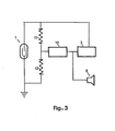
- the horn 8 is controlled by the circuit 10 via a frequency divider circuit with a threshold similar to that shown in FIG. 2. In this variant, the device no longer emits signals sound in the absence of irradiation, but only when the radiation intensity threshold is exceeded.
- the horn 8 is constituted by a piezo-ceramic transducer, connected in series with a self-induction coil in parallel with a transistor.
- the overvoltage caused at the terminals of the self-induction coil considerably amplifies the sound intensity emitted by the transducer.
- a device according to the invention consumes typically 10 microamps for its power supply which, combined with the use of a common miniature battery of low capacity of 90 milliampere-hours, allows one year of operation.
Landscapes
- Physics & Mathematics (AREA)
- Health & Medical Sciences (AREA)
- Life Sciences & Earth Sciences (AREA)
- General Physics & Mathematics (AREA)
- High Energy & Nuclear Physics (AREA)
- Molecular Biology (AREA)
- Spectroscopy & Molecular Physics (AREA)
- Measurement Of Radiation (AREA)
- Other Investigation Or Analysis Of Materials By Electrical Means (AREA)
Applications Claiming Priority (2)
| Application Number | Priority Date | Filing Date | Title |
|---|---|---|---|
| FR8217498 | 1982-10-19 | ||
| FR8217498A FR2534693A1 (fr) | 1982-10-19 | 1982-10-19 | Perfectionnement aux debitmetres d'alarme |
Publications (2)
| Publication Number | Publication Date |
|---|---|
| EP0109871A1 true EP0109871A1 (de) | 1984-05-30 |
| EP0109871B1 EP0109871B1 (de) | 1987-08-05 |
Family
ID=9278398
Family Applications (1)
| Application Number | Title | Priority Date | Filing Date |
|---|---|---|---|
| EP83402033A Expired EP0109871B1 (de) | 1982-10-19 | 1983-10-19 | Vorrichtung zur Messung ionisierender Strahlung |
Country Status (4)
| Country | Link |
|---|---|
| US (1) | US4546257A (de) |
| EP (1) | EP0109871B1 (de) |
| DE (1) | DE3372884D1 (de) |
| FR (1) | FR2534693A1 (de) |
Cited By (1)
| Publication number | Priority date | Publication date | Assignee | Title |
|---|---|---|---|---|
| FR2686158A1 (fr) * | 1992-01-15 | 1993-07-16 | Commissariat Energie Atomique | Chaine de comptage d'impulsions nucleaires a reglage de la haute tension et detection de panne. |
Families Citing this family (5)
| Publication number | Priority date | Publication date | Assignee | Title |
|---|---|---|---|---|
| IL73528A (en) * | 1984-11-16 | 1988-08-31 | Amcor Electronics Ltd | Power supply for electrical detector,particularly for gamma radiation and electrical system including same |
| JP3094437B2 (ja) * | 1990-10-30 | 2000-10-03 | 株式会社島津製作所 | X線分光装置 |
| FR2928459A1 (fr) | 2008-03-06 | 2009-09-11 | Mgp Instr Sa | Procede, systeme et balise de protection par radiographie gamma |
| RU2593820C1 (ru) * | 2015-04-15 | 2016-08-10 | федеральное государственное бюджетное образовательное учреждение высшего образования "Нижегородский государственный технический университет им. Р.Е. Алексеева" (НГТУ) | Многофункциональный инновационный модульный дозиметр |
| KR102925059B1 (ko) * | 2025-09-08 | 2026-02-09 | 주식회사 에프티랩 | 초저전력 라돈 측정 장치 |
Family Cites Families (3)
| Publication number | Priority date | Publication date | Assignee | Title |
|---|---|---|---|---|
| US3428807A (en) * | 1965-03-01 | 1969-02-18 | Ca Atomic Energy Ltd | High voltage supply for radiation detecting equipment |
| US4275388A (en) * | 1980-01-09 | 1981-06-23 | General Electric Company | Piezoelectric audible alarm frequency self-calibration system |
| JPS592078B2 (ja) * | 1980-03-24 | 1984-01-17 | 電探株式会社 | 放電型火災感知器の放電素子駆動回路 |
-
1982
- 1982-10-19 FR FR8217498A patent/FR2534693A1/fr active Granted
-
1983
- 1983-10-19 EP EP83402033A patent/EP0109871B1/de not_active Expired
- 1983-10-19 US US06/543,320 patent/US4546257A/en not_active Expired - Fee Related
- 1983-10-19 DE DE8383402033T patent/DE3372884D1/de not_active Expired
Non-Patent Citations (4)
| Title |
|---|
| ELECTRONICS ENGINEERING, vol. 51, no. 625, juillet 1979, page 18, Londres, GB * |
| HEALTH PHYSICS, vol. 19, no. 5, novembre 1970, pages 692-693, Pergamon Press, IR * |
| HEALTH PHYSICS, vol. 27, no. 1, juillet 1974, pages 97-102, Pergamon Press, IR * |
| PROCEEDINGS OF THE SIXTH TRIPARTITE INSTRUMENTATION CONFERENCE, 22 avril 1959, partie 2: "Radiation dosimetry and health instruments", A.E.C.L. 802, J.E. Woolston & S.J. Townsend, CA * |
Cited By (1)
| Publication number | Priority date | Publication date | Assignee | Title |
|---|---|---|---|---|
| FR2686158A1 (fr) * | 1992-01-15 | 1993-07-16 | Commissariat Energie Atomique | Chaine de comptage d'impulsions nucleaires a reglage de la haute tension et detection de panne. |
Also Published As
| Publication number | Publication date |
|---|---|
| DE3372884D1 (en) | 1987-09-10 |
| US4546257A (en) | 1985-10-08 |
| FR2534693B1 (de) | 1985-01-04 |
| FR2534693A1 (fr) | 1984-04-20 |
| EP0109871B1 (de) | 1987-08-05 |
Similar Documents
| Publication | Publication Date | Title |
|---|---|---|
| EP0110775B1 (de) | Regulierungseinrichtung mit kleiner Verlustspannung | |
| FR2702044A1 (fr) | Circuit de traitement pour signal de sortie de capteur analogique résistif, notamment pour jauge de carburant sur véhicule automobile et systèmes équipés. | |
| EP0109871B1 (de) | Vorrichtung zur Messung ionisierender Strahlung | |
| EP0815635A1 (de) | Leistungsversorgungsschaltung mit einem speicherkondensator | |
| EP0649079A1 (de) | Geregelter Spannungsquellengenerator der Bandgapbauart | |
| EP3591475B1 (de) | Thermoelektrische armbanduhr, die bei der produktion oder im rahmen des kundendienstes getestet werden kann | |
| CH690523A5 (fr) | Pièce d'horlogerie comportant une génératrice d'énergie électrique. | |
| EP0279345B1 (de) | Einrichtung mit Elektronikschaltung für Analogsignalverarbeitung | |
| EP0471625B1 (de) | Vorrichtung zur Erzeugung einer regelbaren Gleichspannung | |
| FR2765045A1 (fr) | Dispositif d'ajustement du courant de charge d'un condensateur de stockage | |
| FR2490895A1 (fr) | Circuit d'entretien pour oscillateur a faible consommation de courant | |
| EP0109914A1 (de) | Anordnung zum Aufspüren von Spannung in elektrischen Installationen | |
| EP0119927B1 (de) | Hochspannungsverstärker für kapazitive Last | |
| FR2628591A1 (fr) | Procede de declenchement d'un electrificateur de cloture et son dispositif de mise en oeuvre | |
| EP0549464A1 (de) | Gerät und Verfahren zur Messung des Ladezustandes eines elektrochemischen Generators | |
| EP0381585B1 (de) | Überwachungsanlage für elektrische Zäune | |
| EP0068970B1 (de) | Stabilisierte Zweipunkt-Steuervorrichtung mit konstanter Periode, und elektrische Speisevorrichtung versehen mit solch einer Steuervorrichtung | |
| EP0848306B1 (de) | Zeitmessgerät mit einem Generator zur Erzeugung elektrischer Energie | |
| FR2719123A1 (fr) | Dispositif de détection de la variation non transitoire d'une tension d'alimentation. | |
| EP0785703B1 (de) | Regelvorrichtung einer Niederdruckleuchtstofflampe | |
| CH462964A (fr) | Appareil détecteur de condition | |
| CH642205A5 (fr) | Circuit amplificateur pour sonde de mesure. | |
| BE834616A (fr) | Dispositif de detection de radiations | |
| EP0450998A1 (de) | Verbesserter Stromgenerator | |
| EP0764895B1 (de) | Schallgenerator, insbesondere für Uhrwerk |
Legal Events
| Date | Code | Title | Description |
|---|---|---|---|
| PUAI | Public reference made under article 153(3) epc to a published international application that has entered the european phase |
Free format text: ORIGINAL CODE: 0009012 |
|
| AK | Designated contracting states |
Designated state(s): CH DE GB LI SE |
|
| 17P | Request for examination filed |
Effective date: 19840709 |
|
| GRAA | (expected) grant |
Free format text: ORIGINAL CODE: 0009210 |
|
| AK | Designated contracting states |
Kind code of ref document: B1 Designated state(s): CH DE GB LI SE |
|
| REF | Corresponds to: |
Ref document number: 3372884 Country of ref document: DE Date of ref document: 19870910 |
|
| PLBE | No opposition filed within time limit |
Free format text: ORIGINAL CODE: 0009261 |
|
| STAA | Information on the status of an ep patent application or granted ep patent |
Free format text: STATUS: NO OPPOSITION FILED WITHIN TIME LIMIT |
|
| 26N | No opposition filed | ||
| PGFP | Annual fee paid to national office [announced via postgrant information from national office to epo] |
Ref country code: GB Payment date: 19911011 Year of fee payment: 9 |
|
| PGFP | Annual fee paid to national office [announced via postgrant information from national office to epo] |
Ref country code: CH Payment date: 19911014 Year of fee payment: 9 |
|
| PGFP | Annual fee paid to national office [announced via postgrant information from national office to epo] |
Ref country code: SE Payment date: 19911028 Year of fee payment: 9 |
|
| PG25 | Lapsed in a contracting state [announced via postgrant information from national office to epo] |
Ref country code: GB Effective date: 19921019 |
|
| PG25 | Lapsed in a contracting state [announced via postgrant information from national office to epo] |
Ref country code: SE Effective date: 19921020 |
|
| PG25 | Lapsed in a contracting state [announced via postgrant information from national office to epo] |
Ref country code: LI Effective date: 19921031 Ref country code: CH Effective date: 19921031 |
|
| PGFP | Annual fee paid to national office [announced via postgrant information from national office to epo] |
Ref country code: DE Payment date: 19921104 Year of fee payment: 10 |
|
| GBPC | Gb: european patent ceased through non-payment of renewal fee |
Effective date: 19921019 |
|
| REG | Reference to a national code |
Ref country code: CH Ref legal event code: PL |
|
| PG25 | Lapsed in a contracting state [announced via postgrant information from national office to epo] |
Ref country code: DE Effective date: 19940701 |
|
| EUG | Se: european patent has lapsed |
Ref document number: 83402033.1 Effective date: 19930510 |