EP0109882A1 - Hydraulische Überlastsicherung für Pflüge - Google Patents
Hydraulische Überlastsicherung für Pflüge Download PDFInfo
- Publication number
- EP0109882A1 EP0109882A1 EP83402131A EP83402131A EP0109882A1 EP 0109882 A1 EP0109882 A1 EP 0109882A1 EP 83402131 A EP83402131 A EP 83402131A EP 83402131 A EP83402131 A EP 83402131A EP 0109882 A1 EP0109882 A1 EP 0109882A1
- Authority
- EP
- European Patent Office
- Prior art keywords
- valve
- accumulator
- pressure
- opening
- piston
- Prior art date
- Legal status (The legal status is an assumption and is not a legal conclusion. Google has not performed a legal analysis and makes no representation as to the accuracy of the status listed.)
- Granted
Links
- 239000007788 liquid Substances 0.000 claims abstract description 8
- 230000000694 effects Effects 0.000 claims description 3
- 238000012423 maintenance Methods 0.000 claims 1
- 238000005096 rolling process Methods 0.000 claims 1
- 239000012530 fluid Substances 0.000 description 2
- 239000011435 rock Substances 0.000 description 2
- 230000001960 triggered effect Effects 0.000 description 2
- 230000000903 blocking effect Effects 0.000 description 1
- 230000005465 channeling Effects 0.000 description 1
- 230000006835 compression Effects 0.000 description 1
- 238000007906 compression Methods 0.000 description 1
- 239000004020 conductor Substances 0.000 description 1
- 230000007423 decrease Effects 0.000 description 1
- JEIPFZHSYJVQDO-UHFFFAOYSA-N iron(III) oxide Inorganic materials O=[Fe]O[Fe]=O JEIPFZHSYJVQDO-UHFFFAOYSA-N 0.000 description 1
- 230000002441 reversible effect Effects 0.000 description 1
- 239000004575 stone Substances 0.000 description 1
Images

Classifications
-
- A—HUMAN NECESSITIES
- A01—AGRICULTURE; FORESTRY; ANIMAL HUSBANDRY; HUNTING; TRAPPING; FISHING
- A01B—SOIL WORKING IN AGRICULTURE OR FORESTRY; PARTS, DETAILS, OR ACCESSORIES OF AGRICULTURAL MACHINES OR IMPLEMENTS, IN GENERAL
- A01B61/00—Devices for, or parts of, agricultural machines or implements for preventing overstrain
- A01B61/04—Devices for, or parts of, agricultural machines or implements for preventing overstrain of the connection between tools and carrier beam or frame
- A01B61/044—Devices for, or parts of, agricultural machines or implements for preventing overstrain of the connection between tools and carrier beam or frame the connection enabling a yielding pivoting movement around a substantially horizontal and transverse axis
- A01B61/046—Devices for, or parts of, agricultural machines or implements for preventing overstrain of the connection between tools and carrier beam or frame the connection enabling a yielding pivoting movement around a substantially horizontal and transverse axis the device including an energy accumulator for restoring the tool to its working position
- A01B61/048—Devices for, or parts of, agricultural machines or implements for preventing overstrain of the connection between tools and carrier beam or frame the connection enabling a yielding pivoting movement around a substantially horizontal and transverse axis the device including an energy accumulator for restoring the tool to its working position the connection or the energy accumulator being active in two opposite directions, e.g. for reversible plows
Definitions
- the present invention relates to plows of the so-called “non-stop” type; that is to say provided with a safety device which allows a plowshare height an obstacle to pivot upwards against an elastic system which brings it back into position after the passage of the obstacle.
- the relative movement of the cylinder relative to the piston compresses a volume of gas already precompressed.
- the cylinder is secured to the frame of the plow and the piston is coupled to the traction rod, the relative movement of the piston relative to the cylinder delivering hydraulic fluid to a hydraulic accumulator.
- the present invention relates more particularly to plows provided with an oleo-pneumatic safety device.
- a threshold effect is thus obtained: according to the setting of the pressure relief valve, a pressure having a predetermined value is required for the valve to open and, as soon as this pressure is reached, the pressure in the circuit is that supplied by the 'accumulator. However, it turns out that as soon as the pressure relief valve opens, the pressure drops and the valve closes, thus blocking the body in an intermediate position.
- the present invention relates to a safety device of the oleo-pneumatic type comprising two circuits in parallel: a first opening circuit or circuit provided with a calibrated opening valve which after opening is kept open, either by the only pressure coming from of the accumulator, either by mechanical means, or even by electrical means; a second circuit, or closing circuit comprising a non-return valve authorizing the circulation of the liquid only in the direction of the cylinder.
- the plow comprises as is known a front end 1 coupled to a tractor by two lower rods 2 and an upper rod 3; this fore-end comprises a splash 4 in which pivots an axis 5 integral with a beam 6 which carries a plurality of T-shaped drawbars, the main branch 7 of which is horizontal and carries a second branch 8 of which each arm carries at its end a plowing bodies 9 and 10 symmetrical, the body 9 having a moldboard pouring to the right and the body 10 having a moldboard pouring to the left.
- each T-shaped drawbar comprises a plate 11 which is in the normal position, kept pressed against a plate 12 secured to the beam 6 by an elastic means.
- This elastic means is constituted by a traction rod 13 articulated at 14 to the plate 12 and connected at its other end to the piston 15 of a jack 16 itself connected to the branch 8 of the drawbar in T by an axis.
- the inner chamber of the jack 16 is connected by a pipe 18 to a valve 20.
- the three jacks 16 of the three T-shaped drawbars are connected in parallel to the same pipe 18.
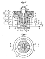
- the valve 20 has an inlet orifice 21, communicating with a small orifice 22, of surface S 1 .
- This orifice 22 is closed by a valve 23 secured to a piston 24 moving in a bore 25a of a second concentric piston 25, while being constrained by a spring 26 whose initial calibration can be adjusted by a screw 27.
- the surface S 2 of the piston 25 is significantly larger than The surface S 1 of the orifice 22.
- the surface S 2 communicates by an outlet orifice 28 with the accumulator 19.
- the surface S 2 also communicates by an orifice 29 with a non-return valve 30 which authorizes the circulation of the fluid only coming from the accumulator 19 towards the jacks 16.
- This pressure acts on the surface S 1 of the valve 23 which is held in position by the spring 26. When this pressure reaches a maximum value, determined by the spring 26 and the surface S 1 , it raises the valve 23. There is therefore pressure increase immediately in the accumulator 19. This pressure acts on the surface S 2 and pushes the piston 25 by compressing the spring 31.
- the piston 24 has longitudinal grooves 24a so that the pressure is equal on the two end surfaces of the piston 24: the latter is therefore balanced.
- the adjustment of the opening pressure of the piston 24 is then independent of any variations in the back pressure from the accumulator 19.
- the pressure prevailing in this circuit is that given by the movement of the piston 15. As long as this pressure is greater than the back pressure supplied by the accumulator 19, the pistons 24 and 25 remain pushed back.
- a mechanism is thus obtained which is maintained in the working position by hydraulic locking, which is triggered for a threshold value which can be very high: in fact, the accumulator can only be pressurized by the hydraulic circuit of the tractor, or at most 120 to 130 bar, while the valve 23 can be calibrated at a level two to three times higher and thus obtain a very high tripping rate for -a reclosing rate corresponding to the normal pressure in the 'accumulator.
- the force on the tip of the plow body immediately drops to a much lower value as soon as the tilting movement is started, but the restoring force is sufficient to return the parts to their original position once the obstacle has passed.
- an auxiliary oleo-pneumatic accumulator can be added connected to the chamber 38 of the valve 20. This can be added to or substituted for the spring 31.
- the valve 20 is integrated into the jack 16. It comprises, as previously, a pressure relief valve 23 held in place by a spring 26. This valve closes the communication between the chamber of the jack 16 and the pipe 28 connected to the accumulator 19 (not shown).
- the valve triggered hydraulically by the pressure in the jack, is kept open by mechanical means: the jack rod has a circular notch 13a in which is housed a ball 44.
- the pressure reaches the value of the initial setting of the valve 23, it lifts, which allows the cylinder rod to move to the left by expelling the liquid through the pipe 31 towards the pipe 28 connected to the accumulator 19 (not shown).
- the ball 44 rolls on the ramp of the notch 13a keeps the valve 23 open by pushing on the stud 23a secured to the valve 23.
- the orifice in which the rod 23b of the valve 23 slides is vented so that the triggering takes place at a precise pressure which is not influenced by parameters foreign to the 'force exerted on the cylinder. It will also be noted that the operation of the overpressure is linked to the length of the area 13a.
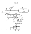
- FIG. 5 represents a third alternative embodiment, the elements identical to those of the preceding figures bearing the same references.
- the pipe 18 through which the piston 15 delivers the liquid from the jack 16 has two branches 32 and 41.
- the valve 20 comprising the pressure relief valve 23 calibrated by the spring adjustable 26;
- a distributor 40 comprising the non-return valve 30.
- the distribution slide 39 of the distributor 40 is electrically controlled by a pressure contact 34 supplied by the electrical circuit 42 connected to the electrical circuit of the tractor.
- the traction exerted by the connecting rod 13 causes an increase in the pressure in the chamber of the jack, in the pipe 18 and the pipes 32 and 41.
- the pipe 41 is closed by the non-return valve 30, while this pressure acts on the valve 23.
- this pressure exceeds the predetermined threshold value, the valve 23 opens and the pipe 18 is put into communication with the accumulator 19 by the pipe 32 and the pipe 43.
- the accumulator 19 is connected to the tractor circuit and pressurized by means of a circuit comprising a valve 35 and a pressure gauge 37.
Landscapes
- Life Sciences & Earth Sciences (AREA)
- Engineering & Computer Science (AREA)
- Mechanical Engineering (AREA)
- Soil Sciences (AREA)
- Environmental Sciences (AREA)
- Fluid-Pressure Circuits (AREA)
- Soil Working Implements (AREA)
- Lifting Devices For Agricultural Implements (AREA)
- Hydraulic Motors (AREA)
- Lubricants (AREA)
Priority Applications (1)
| Application Number | Priority Date | Filing Date | Title |
|---|---|---|---|
| AT83402131T ATE28255T1 (de) | 1982-11-17 | 1983-11-02 | Hydraulische ueberlastsicherung fuer pfluege. |
Applications Claiming Priority (2)
| Application Number | Priority Date | Filing Date | Title |
|---|---|---|---|
| FR8219219 | 1982-11-17 | ||
| FR8219219A FR2535935B1 (fr) | 1982-11-17 | 1982-11-17 | Perfectionnements aux systemes hydrauliques de securite pour charrues a declenchement et reenclenchement automatiques |
Publications (2)
| Publication Number | Publication Date |
|---|---|
| EP0109882A1 true EP0109882A1 (de) | 1984-05-30 |
| EP0109882B1 EP0109882B1 (de) | 1987-07-15 |
Family
ID=9279247
Family Applications (1)
| Application Number | Title | Priority Date | Filing Date |
|---|---|---|---|
| EP83402131A Expired EP0109882B1 (de) | 1982-11-17 | 1983-11-02 | Hydraulische Überlastsicherung für Pflüge |
Country Status (4)
| Country | Link |
|---|---|
| EP (1) | EP0109882B1 (de) |
| AT (1) | ATE28255T1 (de) |
| DE (1) | DE3372435D1 (de) |
| FR (1) | FR2535935B1 (de) |
Cited By (6)
| Publication number | Priority date | Publication date | Assignee | Title |
|---|---|---|---|---|
| FR2587814A1 (fr) * | 1985-09-20 | 1987-03-27 | Huard Ucf | Dispositif de tarage pour appareillage hydraulique de securite, notamment pour charrues |
| DE19652615C1 (de) * | 1996-12-18 | 1998-03-12 | Eberhardt Maschinenfabrik Gmbh | Hydraulische Überlastsicherung für Pflüge |
| FR2764768A1 (fr) * | 1997-06-23 | 1998-12-24 | Forhydro | Dispositif de maintien d'outils en position de travail du sol |
| EP0835051A4 (de) * | 1995-06-30 | 1999-11-17 | Allan James Yeomans | In den boden eindringende geräteverbindung |
| WO2008049216A1 (en) * | 2006-10-24 | 2008-05-02 | Morris Industries Ltd. | Combination hydraulic hold-down and lift system for an agricultural implement |
| EP2425696B1 (de) | 2010-09-06 | 2018-04-04 | Kuhn-Huard S.A. | Pflug mit einer Vorrichtung zum Heben mindestens eines Pflugschars |
Families Citing this family (4)
| Publication number | Priority date | Publication date | Assignee | Title |
|---|---|---|---|---|
| FR2633800B1 (fr) * | 1988-07-08 | 1991-04-26 | Huard Sa | Systeme hydraulique de securite pour charrue |
| US5072793A (en) * | 1990-08-02 | 1991-12-17 | Case Corporation | Trip assembly |
| DE19541581A1 (de) * | 1995-01-23 | 1996-07-25 | Eberhardt Maschinenfabrik Gmbh | Vorrichtung zum Schutz der Arbeitswerkzeuge von Bodenbearbeitungsgeräten gegen Überlastung |
| RU197465U1 (ru) * | 2019-12-30 | 2020-04-29 | Акционерное общество "Алтайский завод сельскохозяйственного машиностроения" | Устройство от перегрузок стоек агрегата при обработке почвы |
Citations (5)
| Publication number | Priority date | Publication date | Assignee | Title |
|---|---|---|---|---|
| US3032122A (en) * | 1960-09-21 | 1962-05-01 | Cletus J Geurts | Spring trip release |
| DE1298343B (de) * | 1966-10-05 | 1969-06-26 | Ventzki Gmbh Eislingen | Hydraulische UEberlastsicherung fuer Bodenbearbeitungswerkzeuge |
| DE1908381A1 (de) * | 1969-02-20 | 1970-09-10 | Rabewerk Clausing Heinrich | Pflug mit UEberlastsicherung |
| US3561541A (en) * | 1967-09-21 | 1971-02-09 | Roger W Woelfel | Tractor and implement hydraulic control system |
| FR2389311A1 (de) * | 1977-05-04 | 1978-12-01 | Lely Nv C Van Der |
-
1982
- 1982-11-17 FR FR8219219A patent/FR2535935B1/fr not_active Expired
-
1983
- 1983-11-02 EP EP83402131A patent/EP0109882B1/de not_active Expired
- 1983-11-02 AT AT83402131T patent/ATE28255T1/de not_active IP Right Cessation
- 1983-11-02 DE DE8383402131T patent/DE3372435D1/de not_active Expired
Patent Citations (5)
| Publication number | Priority date | Publication date | Assignee | Title |
|---|---|---|---|---|
| US3032122A (en) * | 1960-09-21 | 1962-05-01 | Cletus J Geurts | Spring trip release |
| DE1298343B (de) * | 1966-10-05 | 1969-06-26 | Ventzki Gmbh Eislingen | Hydraulische UEberlastsicherung fuer Bodenbearbeitungswerkzeuge |
| US3561541A (en) * | 1967-09-21 | 1971-02-09 | Roger W Woelfel | Tractor and implement hydraulic control system |
| DE1908381A1 (de) * | 1969-02-20 | 1970-09-10 | Rabewerk Clausing Heinrich | Pflug mit UEberlastsicherung |
| FR2389311A1 (de) * | 1977-05-04 | 1978-12-01 | Lely Nv C Van Der |
Cited By (6)
| Publication number | Priority date | Publication date | Assignee | Title |
|---|---|---|---|---|
| FR2587814A1 (fr) * | 1985-09-20 | 1987-03-27 | Huard Ucf | Dispositif de tarage pour appareillage hydraulique de securite, notamment pour charrues |
| EP0835051A4 (de) * | 1995-06-30 | 1999-11-17 | Allan James Yeomans | In den boden eindringende geräteverbindung |
| DE19652615C1 (de) * | 1996-12-18 | 1998-03-12 | Eberhardt Maschinenfabrik Gmbh | Hydraulische Überlastsicherung für Pflüge |
| FR2764768A1 (fr) * | 1997-06-23 | 1998-12-24 | Forhydro | Dispositif de maintien d'outils en position de travail du sol |
| WO2008049216A1 (en) * | 2006-10-24 | 2008-05-02 | Morris Industries Ltd. | Combination hydraulic hold-down and lift system for an agricultural implement |
| EP2425696B1 (de) | 2010-09-06 | 2018-04-04 | Kuhn-Huard S.A. | Pflug mit einer Vorrichtung zum Heben mindestens eines Pflugschars |
Also Published As
| Publication number | Publication date |
|---|---|
| EP0109882B1 (de) | 1987-07-15 |
| FR2535935B1 (fr) | 1986-06-20 |
| DE3372435D1 (en) | 1987-08-20 |
| ATE28255T1 (de) | 1987-08-15 |
| FR2535935A1 (fr) | 1984-05-18 |
Similar Documents
| Publication | Publication Date | Title |
|---|---|---|
| EP0899996B1 (de) | Automatische justierung zur gewichtsentlastung einer maschinenarbeitseniheit:verfahren,vorrichtung und maschine | |
| EP0109882A1 (de) | Hydraulische Überlastsicherung für Pflüge | |
| FR2558027A1 (fr) | Mecanisme de retournement et de reglage pour charrue | |
| FR2992143A1 (fr) | Dispositif d'accouplement perfectionne et machine agricole comportant un tel dispositif | |
| CA2650849A1 (fr) | Machine agricole pour la recolte des fourrages | |
| FR2485322A1 (fr) | Dispositif de relevage et d'abaissement pour outil, instrument ou machine agricole | |
| FR2502450A1 (fr) | Outil ou machine agricole avec dispositif hydraulique de centrage et de verrouillage de la roue pivotante | |
| EP3713391B1 (de) | Landwirtschaftliche maschine mit einem vereinfachten sicherheitssystem, das es einem werkzeug oder einer gruppe von werkzeugen, die durch einen tragarm mit einem anhängebock verbunden sind, ermöglicht, eine sicherheitsbewegung auszuführen | |
| BE481624A (de) | ||
| FR2586890A1 (fr) | Systemes hydrauliques de securite a clapet double pour charrue a declenchement et reenclenchement automatiques | |
| EP0350343B1 (de) | Hydraulisches Sicherheitssystem für Pflüge | |
| FR2538446A1 (fr) | Dispositif de commande des verins de toits coulissants d'unites de soutenement marchants hydrauliques, et verin de travail commande par le dispositif | |
| FR2763472A1 (fr) | Dechaumeur avec reglage hydraulique de rouleau et disques | |
| FR2469094A1 (fr) | Perfectionnements aux charrues pour le labour sans interruption | |
| EP0087334A1 (de) | Überlast-Sicherheitseinrichtung für Pflüge | |
| FR2704718A1 (fr) | Dispositif de retenue pour un dispositif de dégagement de balles. | |
| FR2763471A1 (fr) | Dechaumeur avec securite d'effacement | |
| EP3868189B1 (de) | Gelenkzugarmvorrichtung und mit einem solchen arm ausgestattete landwirtschaftliche maschine | |
| FR2478423A1 (fr) | Dispositif hydropneumatique compense pour charrues pivotantes | |
| EP1639875B1 (de) | Aufsattel-Pflug mit einer verstellbaren Vorrichtung mit Speicher | |
| FR2473082A1 (fr) | Sous-soleuse a corps draineur perfectionnee avec reglage oleo-dynamique de l'incidence de l'outil travaillant | |
| FR2593992A1 (fr) | Dispositif de securite pour charrues. | |
| BE500908A (de) | ||
| FR2944180A1 (fr) | Charrue reversible avec dispositif de reduction de pression | |
| FR3165754A1 (fr) | Dispositif de binage destiné à être tracté, comprenant un parallélogramme déformable portant au moins un élément de binage |
Legal Events
| Date | Code | Title | Description |
|---|---|---|---|
| PUAI | Public reference made under article 153(3) epc to a published international application that has entered the european phase |
Free format text: ORIGINAL CODE: 0009012 |
|
| AK | Designated contracting states |
Designated state(s): AT BE CH DE GB IT LI NL SE |
|
| 17P | Request for examination filed |
Effective date: 19841109 |
|
| RAP1 | Party data changed (applicant data changed or rights of an application transferred) |
Owner name: SOCIETE DE CONSTRUCTIONS MECANIQUES HUARD-UCF SOC |
|
| GRAA | (expected) grant |
Free format text: ORIGINAL CODE: 0009210 |
|
| AK | Designated contracting states |
Kind code of ref document: B1 Designated state(s): AT BE CH DE GB IT LI NL SE |
|
| PG25 | Lapsed in a contracting state [announced via postgrant information from national office to epo] |
Ref country code: NL Effective date: 19870715 Ref country code: IT Free format text: LAPSE BECAUSE OF FAILURE TO SUBMIT A TRANSLATION OF THE DESCRIPTION OR TO PAY THE FEE WITHIN THE PRESCRIBED TIME-LIMIT;WARNING: LAPSES OF ITALIAN PATENTS WITH EFFECTIVE DATE BEFORE 2007 MAY HAVE OCCURRED AT ANY TIME BEFORE 2007. THE CORRECT EFFECTIVE DATE MAY BE DIFFERENT FROM THE ONE RECORDED. Effective date: 19870715 Ref country code: AT Effective date: 19870715 |
|
| REF | Corresponds to: |
Ref document number: 28255 Country of ref document: AT Date of ref document: 19870815 Kind code of ref document: T |
|
| PG25 | Lapsed in a contracting state [announced via postgrant information from national office to epo] |
Ref country code: SE Effective date: 19870731 |
|
| REF | Corresponds to: |
Ref document number: 3372435 Country of ref document: DE Date of ref document: 19870820 |
|
| PG25 | Lapsed in a contracting state [announced via postgrant information from national office to epo] |
Ref country code: LI Effective date: 19871130 Ref country code: CH Effective date: 19871130 Ref country code: BE Effective date: 19871130 |
|
| NLV1 | Nl: lapsed or annulled due to failure to fulfill the requirements of art. 29p and 29m of the patents act | ||
| PLBE | No opposition filed within time limit |
Free format text: ORIGINAL CODE: 0009261 |
|
| STAA | Information on the status of an ep patent application or granted ep patent |
Free format text: STATUS: NO OPPOSITION FILED WITHIN TIME LIMIT |
|
| BERE | Be: lapsed |
Owner name: SOC. DE CONSTRUCTIONS MECANIQUES HUARD-UCF S.A. Effective date: 19871130 |
|
| 26N | No opposition filed | ||
| REG | Reference to a national code |
Ref country code: CH Ref legal event code: PL |
|
| PGFP | Annual fee paid to national office [announced via postgrant information from national office to epo] |
Ref country code: GB Payment date: 19921026 Year of fee payment: 10 |
|
| PGFP | Annual fee paid to national office [announced via postgrant information from national office to epo] |
Ref country code: DE Payment date: 19921130 Year of fee payment: 10 |
|
| PG25 | Lapsed in a contracting state [announced via postgrant information from national office to epo] |
Ref country code: GB Effective date: 19931102 |
|
| GBPC | Gb: european patent ceased through non-payment of renewal fee |
Effective date: 19931102 |
|
| PG25 | Lapsed in a contracting state [announced via postgrant information from national office to epo] |
Ref country code: DE Effective date: 19940802 |