EP0109905A1 - Vorrichtung zum Biegen von Rohren - Google Patents
Vorrichtung zum Biegen von Rohren Download PDFInfo
- Publication number
- EP0109905A1 EP0109905A1 EP19830402217 EP83402217A EP0109905A1 EP 0109905 A1 EP0109905 A1 EP 0109905A1 EP 19830402217 EP19830402217 EP 19830402217 EP 83402217 A EP83402217 A EP 83402217A EP 0109905 A1 EP0109905 A1 EP 0109905A1
- Authority
- EP
- European Patent Office
- Prior art keywords
- tube
- roller
- bending
- axis
- inner roller
- Prior art date
- Legal status (The legal status is an assumption and is not a legal conclusion. Google has not performed a legal analysis and makes no representation as to the accuracy of the status listed.)
- Granted
Links
- 238000005452 bending Methods 0.000 title claims abstract description 59
- 238000007493 shaping process Methods 0.000 abstract description 2
- 230000007423 decrease Effects 0.000 description 2
- 238000004519 manufacturing process Methods 0.000 description 2
- 238000010008 shearing Methods 0.000 description 2
- 241001080024 Telles Species 0.000 description 1
- 238000012986 modification Methods 0.000 description 1
- 230000004048 modification Effects 0.000 description 1
- 230000002093 peripheral effect Effects 0.000 description 1
Images

Classifications
-
- B—PERFORMING OPERATIONS; TRANSPORTING
- B21—MECHANICAL METAL-WORKING WITHOUT ESSENTIALLY REMOVING MATERIAL; PUNCHING METAL
- B21D—WORKING OR PROCESSING OF SHEET METAL OR METAL TUBES, RODS OR PROFILES WITHOUT ESSENTIALLY REMOVING MATERIAL; PUNCHING METAL
- B21D7/00—Bending rods, profiles, or tubes
- B21D7/08—Bending rods, profiles, or tubes by passing between rollers or through a curved die
Definitions
- the hydraulic brake control lines consist of relatively rigid sections of tubes, but having a certain malleability, comprising rectilinear parts connected by curved parts; these are generally left-hand pieces of which only the joint rectilinear parts are two by two in the same plane with the curved part which connects them; the ends of these tube sections are further provided with threaded connections, and shaped so that these connections cannot escape.
- the present invention relates to a machine capable of automatically manufacturing such pipes, whatever their type, dimensions and size, provided that it is provided with all the data corresponding to the desired pipe.
- Bending heads are known through which the tube to be bent arrives axially and passes between two bending rollers, of which an inner roller has a radius equal to the radius of curvature of the desired bending, and an outer roller, whose axis is rotatable around that of the fixed roller situated on a line passing through the axis of the internal roller and which, in the inactive position of the external roller, is perpendicular to the axis of the bending head along which the tube to be bent arrives, with means to rotate it around the axis of the inner roller by an angle equal to the angle at the center desired for this curved part.
- rollers preferably have peripheral grooves whose radius is substantially equal to the outside radius of the tubes to be bent, so that they are held peripherally and do not tend to collapse during their bending.
- the bending has a radius of curvature which is a function of the angle at the center of which the axis of the outer roller is rotated around that of the inner roller, and which decreases as the latter increases ; one can find by calculations or by tests, on the one hand, the angle which must rotate the axis of the outer roller around that of the inner roller to obtain a bending of a tube of determined outer diameter whose curve has the desired radius of curvature, and, on the other hand, the length which must advance the tube, and subject it to this bending without modifying the angular position of the outer roller, so that the curved part obtained has the angle at the desired center.
- the machine comprises a guide nozzle fixed to its front part, immediately behind the internal bending roller, so that it is traversed axially by the tube intended to be bent and that it s opposes the deformation thereof by reaction in opposite direction to that caused by its bending around the inner roller under the action of the outer roller.
- the machine must of course further include means for advancing the tube to be bent along the axis of its bending head in order to obtain, first, a first straight portion of the desired length, then an equal straight length to that of the contiguous curved part to be produced with a curve having the angle at the desired center, means for pivoting the bending head around the tube by the desired angle so that its working plane is that in which it must be located the contiguous curved part and the rectilinear part which will extend it, and means for pivoting the outer roller around the axis of the inner roller by an angle such that the curved part which it shapes by its rotation has the radius of curvature desired, said means continuing to intervene successively to produce each curved part and the straight part which extends it into the piping.
- Means can also be provided for cutting the tube below the pipe which has just been completed, and other means for shaping the two ends of the pipe and adapting the conventional threaded connections which it must include.
- the machine can be fed by rolls of tubes which can be from 2000 to 3000 meters in length, for example, which has a very great advantage for keeping these tubes in good condition, which deteriorate when they are cut in advance.
- the arrangement must be such that each of these means intervenes automatically, in turn, and for the time necessary to be able to execute the desired operation, as it has been programmed.
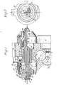
- the bending head shown in Figures 1 and 2 has an inner roller 1, rotatable about a fixed axis 2, and an outer roller 3, rotatable around an axis 4, which is itself pivotally mounted around the axis 2 of the inner roller 1; in the rest position shown, in which these rollers produce no bending, the line joining the axes 2 and 4 of the two rollers 1 and 3 is perpendicular to the axis of the tube 5 intended to be bent by the combined action of the two rollers 1 and 3 and which passes through said bending head.
- the motor 6 which, by means of the bevel gears 7 and 7a and the straight gears 8, 8a and 8b, drives the outer rack 9 in translation sleeve 10, parallel to tube 5; at the front part of this sleeve 10 are articulated the rear ends of two symmetrical connecting rods 11, the front ends of which are articulated on the lower part of a part 12, forming a yoke, the wings of which are rotatably mounted on the axis 2 of the inner roller l, and between which is mounted the axis 4 of the outer roller 3.
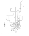
- the axis 4 of the movable roller 3 is at a distance from the axis 2 of the fixed roller 1 such that there remains between these rollers a slightly larger free space than the diameter of the tube 5; under these conditions, the bending of the tube 5 does not begin until the outer roller 3 comes into contact with the extension 5a of the tube 5, and ensures its bending with a radius of curvature which is a function of the angle which is made turn this outer roller 3 around the axis 2 of the inner roller 1; thus, as shown in Figure 3, when the outer roller 3 has arrived in position 3a, the straight extension of the tube 5 is first located at 5 " ' a; the tube 5 is tangent to the inner roller 1 and the outer roller 3 with a curved part whose center of curvature is O, on the lines joining the axes 2 and 4 of the rollers 1 and 3 at the points of tangency of the tube on these rollers; the corresponding radius of curvature decreases
- This curved part of the tube 5 is extended by its straight part 5 "a which tangents the outer roller 3; the angle at the center of this curved part is equal to that which the outer roller 3 has been made to pivot about the axis 2 of the inner roller 1; if we want to increase this angle at the center, it suffices to continue advancing the tube 5 through the bending head without modifying the position of the outer roller 3, until this angle reaches l 'desired amplitude; the straight extension of the bending tube is then in position 5 "' a.
- a guide nozzle 37 is fixed to its front part, immediately behind the internal bending roller 1, so that it is axially traversed by the tube 5 intended to be bent and that it s opposes the deformation of the latter by reaction in the opposite direction to that caused by its bending around the inner roller 1 under the action of the outer roller 3.
- the plane of this bending head can be modified at will because its active part 14 on which are mounted the inner 1 and outer 3 bending rollers, is itself rotatable inside the sliding sleeve 10, which itself is held in a fixed angular position by the plate 15, sliding in the frame 16 of the bending head and engaged in a longitudinal groove 17 provided for this purpose in the sleeve 10.
- the bending head shown further comprises a device for shearing the section of tube whose bending has just been completed; it is constituted by two knobs 21 integral in rotation with the pivoting part 14 and mounted, for this purpose, at the inner end of two pushers 22 forming yokes, sliding in corresponding radial bores 23 of the pivoting part 14; the outer edges 25 of these radial pushers 22 are inclined so as to constitute cams cooperating with the female conical surfaces 26 of the front part of the sliding annular part 27; to shear the tube 5, compressed air is made to penetrate through the orifice 28 into 1 "free space 29 provided between the frame 16 and the rear part of the sliding annular part 27, which causes the rearward sliding of this part 27, against a return spring, and, as a result, a centripetal force exerted on the pushers forming yokes 22, the two knobs 21 of which cut the tube, in particular if the pivoting part is driven 14 rotating at high speed by means of the motor 18.
- such a bending head 30 is mounted on the frame 31 with its three motors, 6 for controlling the pivoting of the axis 4 of the outer roller 3 around that of the inner roller 1 , the motor 18 which makes it possible to pivot the bending plane of the bending head 30 around the tube to be bent 5, and the motor 32 which drives the pairs of rollers 33 which cause the desired sliding of the tube 5 through the head of bending.
- the machine further comprises a retractable device 33 allowing, before the commencement of the operations of bending the tube 5, to present before the latter, at 34, a threaded connection coming from the supply ramp 35, in a manner known per se, through which the anterior end of said tube is engaged; a suitable device then shapes the front end of this tube so that this threaded connection can no longer escape forward.
- the rear end of the pipe section which has just been bent and separated, by shearing, from the tube of which it formed the front part, may likewise be provided with a threaded connection and be shaped so that it cannot escape backwards.
Landscapes
- Engineering & Computer Science (AREA)
- Mechanical Engineering (AREA)
- Bending Of Plates, Rods, And Pipes (AREA)
Applications Claiming Priority (2)
| Application Number | Priority Date | Filing Date | Title |
|---|---|---|---|
| FR8219404A FR2536314B1 (fr) | 1982-11-19 | 1982-11-19 | Machine a cintrer les tubes |
| FR8219404 | 1982-11-19 |
Publications (2)
| Publication Number | Publication Date |
|---|---|
| EP0109905A1 true EP0109905A1 (de) | 1984-05-30 |
| EP0109905B1 EP0109905B1 (de) | 1987-07-15 |
Family
ID=9279333
Family Applications (1)
| Application Number | Title | Priority Date | Filing Date |
|---|---|---|---|
| EP19830402217 Expired EP0109905B1 (de) | 1982-11-19 | 1983-11-17 | Vorrichtung zum Biegen von Rohren |
Country Status (3)
| Country | Link |
|---|---|
| EP (1) | EP0109905B1 (de) |
| DE (1) | DE3372447D1 (de) |
| FR (1) | FR2536314B1 (de) |
Cited By (3)
| Publication number | Priority date | Publication date | Assignee | Title |
|---|---|---|---|---|
| US5388441A (en) * | 1992-12-29 | 1995-02-14 | United States Surgical Corporation | Needle curver with automatic feed |
| RU2138353C1 (ru) * | 1997-07-28 | 1999-09-27 | Акционерное общество "Электростальский завод тяжелого машиностроения" | Устройство для гибки длинномерных труб |
| CN117840275A (zh) * | 2024-03-06 | 2024-04-09 | 山西中德管业有限公司 | 一种用于管道弯折的加工装置 |
Families Citing this family (1)
| Publication number | Priority date | Publication date | Assignee | Title |
|---|---|---|---|---|
| RU2221666C1 (ru) * | 2002-05-13 | 2004-01-20 | Общество с ограниченной ответственностью фирма "Саратовгазприборавтоматика" | Устройство для навивки металлических труб в змеевик |
Citations (5)
| Publication number | Priority date | Publication date | Assignee | Title |
|---|---|---|---|---|
| US3373587A (en) * | 1966-12-08 | 1968-03-19 | Shubin Vladimir Nikolaevich | Automatic tube bending machines |
| FR2208728A1 (de) * | 1972-11-30 | 1974-06-28 | Shubin Vladimir | |
| FR2311604A1 (fr) * | 1975-05-21 | 1976-12-17 | Shubin Vladimir | Tete de pliage pour machine a plier les tubes |
| FR2312312A1 (fr) * | 1975-03-04 | 1976-12-24 | Shubin Vladimir | Machine-outil a plier les tubes |
| US4161110A (en) * | 1977-04-28 | 1979-07-17 | EVG Entwicklungs- und Verwertungs-Gesellschaft mbH. | Automatic control device for a bending machine |
-
1982
- 1982-11-19 FR FR8219404A patent/FR2536314B1/fr not_active Expired
-
1983
- 1983-11-17 DE DE8383402217T patent/DE3372447D1/de not_active Expired
- 1983-11-17 EP EP19830402217 patent/EP0109905B1/de not_active Expired
Patent Citations (5)
| Publication number | Priority date | Publication date | Assignee | Title |
|---|---|---|---|---|
| US3373587A (en) * | 1966-12-08 | 1968-03-19 | Shubin Vladimir Nikolaevich | Automatic tube bending machines |
| FR2208728A1 (de) * | 1972-11-30 | 1974-06-28 | Shubin Vladimir | |
| FR2312312A1 (fr) * | 1975-03-04 | 1976-12-24 | Shubin Vladimir | Machine-outil a plier les tubes |
| FR2311604A1 (fr) * | 1975-05-21 | 1976-12-17 | Shubin Vladimir | Tete de pliage pour machine a plier les tubes |
| US4161110A (en) * | 1977-04-28 | 1979-07-17 | EVG Entwicklungs- und Verwertungs-Gesellschaft mbH. | Automatic control device for a bending machine |
Cited By (5)
| Publication number | Priority date | Publication date | Assignee | Title |
|---|---|---|---|---|
| US5388441A (en) * | 1992-12-29 | 1995-02-14 | United States Surgical Corporation | Needle curver with automatic feed |
| US5450739A (en) * | 1992-12-29 | 1995-09-19 | United States Surgical Corporation | Needle curver with automatic feed |
| RU2138353C1 (ru) * | 1997-07-28 | 1999-09-27 | Акционерное общество "Электростальский завод тяжелого машиностроения" | Устройство для гибки длинномерных труб |
| CN117840275A (zh) * | 2024-03-06 | 2024-04-09 | 山西中德管业有限公司 | 一种用于管道弯折的加工装置 |
| CN117840275B (zh) * | 2024-03-06 | 2024-05-31 | 山西中德管业有限公司 | 一种用于管道弯折的加工装置 |
Also Published As
| Publication number | Publication date |
|---|---|
| DE3372447D1 (en) | 1987-08-20 |
| FR2536314B1 (fr) | 1985-06-21 |
| FR2536314A1 (fr) | 1984-05-25 |
| EP0109905B1 (de) | 1987-07-15 |
Similar Documents
| Publication | Publication Date | Title |
|---|---|---|
| EP0148061A1 (de) | Vorrichtung zur kontinuierlichen Herstellung einer Rohrstruktur aus gebördeltem und schraubenförmig gewickeltem Bandmaterial | |
| FR2558394A1 (fr) | Appareil perfectionne pour le nettoyage des tuyaux d'ecoulement | |
| EP1606079A1 (de) | Maschine zum schleifen von optischen linsen | |
| FR2565520A1 (fr) | Dispositif de coupe automatique des tubes en carton et autres | |
| EP0141745B1 (de) | Automatische Maschine zum Biegen in einer räumlichen Konfiguration feiner und gerader Elemente, insbesondere Metalldrähten | |
| FR2464114A1 (fr) | Dispositif pour le realesage d'arbres creux | |
| EP0168331B1 (de) | Maschine zum Biegen von Rohren, Stangen oder Profilen | |
| CA2867641C (fr) | Machine de cintrage a tete de pliage mobile autour d'un nez de pliage fixe | |
| WO2023079232A1 (fr) | Machine d'étiquetage d'un objet cylindrique tel qu'un câble | |
| FR2751256A1 (fr) | Machine de meulage de verres optiques | |
| FR2513492A1 (fr) | Dispositif pour le retournement d'objets en forme de tiges tels qu'en particulier des cigarettes | |
| EP0414599B1 (de) | Bindevorrichtung mit Verdrillkopf und mit solchen Bindevorrichtungen ausgerüstete Bindemaschinen, vorzugsweise für das Binden von Metalldrahtbündeln | |
| FR2613644A1 (fr) | Dispositif de cintrage tridimensionnel de materiau en forme de fil | |
| EP0109905B1 (de) | Vorrichtung zum Biegen von Rohren | |
| EP0356389B1 (de) | Antriebsvorrichtung für eine Mehrspindelbearbeitungsmaschine | |
| FR2501546A1 (fr) | Appareil pour former un trou a bord releve dans la paroi d'un tuyau | |
| EP1313577B1 (de) | Biegevorrichtung für metalldraht | |
| EP1311356B1 (de) | Vorrichtung zum biegen von rohren | |
| EP0795504A1 (de) | Maschine zum kontinuierlichen Abwickeln von Bobinen mit zumindest einer Einrichtung zum gleichzeitigen Abwickeln von zwei paarweise oder koaxial angeordneten Bobinen | |
| BE1008111A3 (fr) | Taraud machine. | |
| FR2749199A1 (fr) | Machine de cambrage de fils metalliques | |
| FR2554747A1 (fr) | Outil pour le tronconnage de tubes | |
| EP0517637A1 (de) | Biegekopf mit Mehrfachwerkzeugen für eine Drahtbiegemaschine | |
| FR3128945A1 (fr) | Machine d’étiquetage d’un objet cylindrique tel qu’un câble | |
| EP0263763B1 (de) | Bearbeitungsvorrichtung für Rohrenden aus faserverstärktem Gummi |
Legal Events
| Date | Code | Title | Description |
|---|---|---|---|
| PUAI | Public reference made under article 153(3) epc to a published international application that has entered the european phase |
Free format text: ORIGINAL CODE: 0009012 |
|
| AK | Designated contracting states |
Designated state(s): DE GB IT |
|
| 17P | Request for examination filed |
Effective date: 19841120 |
|
| GRAA | (expected) grant |
Free format text: ORIGINAL CODE: 0009210 |
|
| AK | Designated contracting states |
Kind code of ref document: B1 Designated state(s): DE GB IT |
|
| ITF | It: translation for a ep patent filed | ||
| REF | Corresponds to: |
Ref document number: 3372447 Country of ref document: DE Date of ref document: 19870820 |
|
| PLBE | No opposition filed within time limit |
Free format text: ORIGINAL CODE: 0009261 |
|
| STAA | Information on the status of an ep patent application or granted ep patent |
Free format text: STATUS: NO OPPOSITION FILED WITHIN TIME LIMIT |
|
| 26N | No opposition filed | ||
| PGFP | Annual fee paid to national office [announced via postgrant information from national office to epo] |
Ref country code: DE Payment date: 19920131 Year of fee payment: 9 |
|
| PGFP | Annual fee paid to national office [announced via postgrant information from national office to epo] |
Ref country code: GB Payment date: 19921113 Year of fee payment: 10 |
|
| ITTA | It: last paid annual fee | ||
| PG25 | Lapsed in a contracting state [announced via postgrant information from national office to epo] |
Ref country code: DE Effective date: 19930803 |
|
| PG25 | Lapsed in a contracting state [announced via postgrant information from national office to epo] |
Ref country code: GB Effective date: 19931117 |
|
| GBPC | Gb: european patent ceased through non-payment of renewal fee |
Effective date: 19931117 |