EP0110050A1 - Unité de disques pour disques souples à différentes largeurs de piste - Google Patents
Unité de disques pour disques souples à différentes largeurs de piste Download PDFInfo
- Publication number
- EP0110050A1 EP0110050A1 EP83109589A EP83109589A EP0110050A1 EP 0110050 A1 EP0110050 A1 EP 0110050A1 EP 83109589 A EP83109589 A EP 83109589A EP 83109589 A EP83109589 A EP 83109589A EP 0110050 A1 EP0110050 A1 EP 0110050A1
- Authority
- EP
- European Patent Office
- Prior art keywords
- flexible disc
- erasing
- head
- core
- set forth
- Prior art date
- Legal status (The legal status is an assumption and is not a legal conclusion. Google has not performed a legal analysis and makes no representation as to the accuracy of the status listed.)
- Granted
Links
Images


Classifications
-
- G—PHYSICS
- G11—INFORMATION STORAGE
- G11B—INFORMATION STORAGE BASED ON RELATIVE MOVEMENT BETWEEN RECORD CARRIER AND TRANSDUCER
- G11B19/00—Driving, starting, stopping record carriers not specifically of filamentary or web form, or of supports therefor; Control thereof; Control of operating function ; Driving both disc and head
- G11B19/02—Control of operating function, e.g. switching from recording to reproducing
- G11B19/12—Control of operating function, e.g. switching from recording to reproducing by sensing distinguishing features of or on records, e.g. diameter end mark
- G11B19/128—Control of operating function, e.g. switching from recording to reproducing by sensing distinguishing features of or on records, e.g. diameter end mark involving the detection of track pitch or recording density
-
- G—PHYSICS
- G11—INFORMATION STORAGE
- G11B—INFORMATION STORAGE BASED ON RELATIVE MOVEMENT BETWEEN RECORD CARRIER AND TRANSDUCER
- G11B5/00—Recording by magnetisation or demagnetisation of a record carrier; Reproducing by magnetic means; Record carriers therefor
- G11B5/012—Recording on, or reproducing or erasing from, magnetic disks
- G11B5/016—Recording on, or reproducing or erasing from, magnetic disks using magnetic foils
-
- G—PHYSICS
- G11—INFORMATION STORAGE
- G11B—INFORMATION STORAGE BASED ON RELATIVE MOVEMENT BETWEEN RECORD CARRIER AND TRANSDUCER
- G11B5/00—Recording by magnetisation or demagnetisation of a record carrier; Reproducing by magnetic means; Record carriers therefor
- G11B5/127—Structure or manufacture of heads, e.g. inductive
- G11B5/265—Structure or manufacture of a head with more than one gap for erasing, recording or reproducing on the same track
- G11B5/2652—Structure or manufacture of a head with more than one gap for erasing, recording or reproducing on the same track with more than one gap simultaneously operative
- G11B5/2654—Structure or manufacture of a head with more than one gap for erasing, recording or reproducing on the same track with more than one gap simultaneously operative for recording or erasing
- G11B5/2655—Structure or manufacture of a head with more than one gap for erasing, recording or reproducing on the same track with more than one gap simultaneously operative for recording or erasing with all the gaps disposed within the track or "guard band" between tracks, e.g. with erase gaps operative on track edges, with wide erase gap followed by narrow write gap
Definitions
- This invention relates to flexible disc devices for storing information, and more particularly to system for securing the information compatibility between memory media being different in track density in a flexible disc device and to a magnet head assembly being suitable to the system.
- some conventional device distinguishes difference in coercive force of recording medium or magnetic property of coated film thickness.
- a notch is provided at a specific_position of a jacket so as to prevent the data error by use of high-density medium in a conventional device or inversely use of ordinary medium in a high-density device and to detect the use mistake.
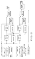
- the device is so constituted that a medium discrimination detector A informs an operator of mistake in setting a flexible disc, and the information is transmitted through a medium setting error detecting circuit B and a signal connector to a host computer C as shown in Fig. 1. In a series of operation, the use mistake is informed to the operator and the host computer C so as to inhibit the writing or reading action.
- Fig. 1 shows many circuits and elements without reference numeral. Since basic function of these elements is known by those skilled in the art and little part relates directly to this invention, description of these elements is omitted now and will be performed when required.
- Other device of 96 TPI can be used for both high density medium and ordinary medium.
- use of inside track having high line recording density is inhibited at using ordinary medium and writing current is changed corresponding to difference in property of medium.
- Fig. 1 shows a conventional example particularly realizing the high density, and use device commonly used in the prior art had no medium discrimination detector.
- information of 48 TPI written in the same medium property i.e. the same line recording density can be read by a device of 96 TPI in prior art. This is because the center portion of track in 48 TPI is made coincident with that of track of even number in 96 TPI.
- a disc recorded in a device of 48 TPI can be read by a device of 48 TPI; a disc recorded in 96 TPI cannot be read by 48 TPI. That is, the compatibility of mutual medium writing does not exist in the strict meaning.
- this invention intends to provide system such as small computer wherein a large amount of software store contained in a large number of discs prepared by an ordinary flexible disc device remains intact and can be successively read and written again for use in new system.
- This invention provides an approach to rewrite ordinary disc of 48 TPI in a new large-capacity' device of 96 TPI so that it can be read also in conventional device of 48 TPI, for example, this invention proposes following requirements.
- the invention utilizes a new magnetic head having the bidirectional compatibility wherein information recorded in 48 PSI, for example, can be read in 96 TPI and information recorded in 96 TPI can be read by a conventional device of 48 TPI.
- the invention includes means for discriminating the recording track density of a flexible disc in use.
- This means may be installed at inside of the device corresponding to shape of a jacket or otherwise at outside of the device so that the detection is performed using software in a host computer corresponding to the read information.
- this invention contains means for changing the recording effective track width of magnetic head electrically during rewriting on the disc corresponding to the track density signal discriminated as above described.
- the recording effective track width includes the erase band width used usually in a flexible disc device.
- the invention is used in that the track density signal discriminated as above described is transmitted to the host computer by any method and used to change over the track number usable as a host computer.
- the changing over is unnecessary when track density is detected using software at the host side.
- the invention may include means for changing the shift amount of head positioning by the track density discriminating signal in the drive corresponding to the discriminated PSI.
- the recording current or electric property of reading circuit can be changed in accordance with the track density discriminating signal as above described. This is required particularly when the line record density is different between large-capacity medium and ordinary medium or when magnetic property is different between media.
- the transfer frequency of controller for a host controller or the like and the center frequency of synchronous circuit of the data demodulation circuit may be changed with the above-mentioned track density discriminating signal.
- the disc with different track density is different also in data transfer frequency caused by difference of the record density.
- the rotating speed of the disc can be altered according to the above-mentioned track density discriminating signal.
- discs being different in the line recording density can be recorded and regenerated in the same transfer frequency, and the optimum rotating speed can be selected for respective discs.
- Still another object of the invention is to provide a magnetic head assembly which is suitable for attaining the above-mentioned objects.
- a magnetic head assembly of the invention comprises means for varying the effective width erased on the magnetic recording medium.
- means for varying the effective width erased on the magnetic recording medium As an example of specific means, two pairs of erasing head gaps are provided at both sides of writing/reading head cores of effective erase width, only a pair of gaps at inside or both of two pairs are energized thereby electric changing can be performed.
- a flexible disc device as an embodiment of the present invention is a magnetic record information memory of rotary type which is compact and convenient as shown in a schematic view of Fig. 2.
- a storage medium of the device is an exchangeable flexible disc cartridge, that is, a disc 1 which is formed by applying magnetic recording medium ot a plastic film of polyester and enclosed in a rectangular jacket 2.
- the flexible disc 1 within the jacket is rotated by a motor 3 and a spindle 4 at a constant speed specified corresponding to the disc 1 in use.
- a magnetic head 7 is one in number at one-surface type.
- the magnetic head 7 in working is contacted with the disc 1.
- a carriage 8 to hold the head 7 is moved on guide rods 9 in the direction of disc diameter.
- Positioning of the head is performed by a step motor 5 through a steel belt mechanism 6 such as shown in Fig. 2.
- reference numeral 10 designates a medium discrimination detector utilizing a detector for detecting medium attaching error in the prior art. Function of the medium discrimination detector 10 in the prior art and the invention will be described later.
- Numeral 11 designates a rotating speed detector for the DC spindle motor 3.
- Numeral 12 designates a peripheral circuit for receiving. and sending data and control signals and processing them between the above mentioned DC spindle motor 3, step motor 5, head 7, medium discrimination detector 10 and rotating speed detector 11.
- the peripheral circuit 12 includes various circuits as shown in Fig. 3.
- Numeral 14 designates a host computer, and a personal computer known in the prior art, such as IBM 5150 type, Apple III, Mult. 16 of Apple Co. or PC-8001 of Nippon Electric Co. can be used therefor. Detailed description of the host computer 14 will be omitted.
- Fig. 3 shows a block diagram of a flexible disc device according to the invention, in which same reference numerals in Fig. 2 denote the same or like parts.
- the medium discrimination detector 10 distinguishes shape of the flexible disc 2 shown in Fig. 2, i.e. a notch or a hole using an optical sensor.
- a disc having a notch represents a new type of high density e.g. a disc of 96 TPI. This detection can be performed also using a microswitch or the like.
- Electric signal which is detected by the detector 10 and discriminated by the medium discrimination circuit 12 for representing the high track density is transmitted through a signal connector 13 to a disc controller in the computer.
- the electric signal is also supplied to an erasing head current drive circuit 71, a writing/ reading circuit 72 and a step motor drive circuit 51 as shown in thick solid line of Fig. 3.
- a magnetic head 7 used in a conventional device has the magnetic pole structure as shown in Fig. 4, but that used in an embodiment of the invention has the pole structure as shown in Fig. 5.
- numeral 21 designates a writing/reading head core
- numeral 22 a writing/reading gap
- numeral 23 an erasing head core
- numeral 24 an erasing gap.
- the erasing head and the gap are halved into 23a, 23b and 24a, 24b, respectively.
- numeral 25, 26 designate non-magnetic spacers
- numerals 27, 28 designate slide shoes.
- the erasing head drive circuit 71 is constituted as shown in Fig. 6.
- Fig. 6 is the track density changing signal made "1" signal at 48 TPI, current flows through both erase A and erase B at recording state and erasing gaps 24a and 24b are energized, thereby old signal is erased throughout wide region corresponding to 48 TPI.
- New recording signal is written at the writing/ reading gap 22 and becomes the optimum width for 96 TPI. Therefore, if recording of 48 TPI is effected in this state, width becomes about a half in comparison to writing state using an ordinary device of 48 TPI. If the signal is read by ordinary device of 48 TPI, the signal output becomes about a half. However, since the disc contacting to the wide gap 22 of device of 48 TPI is widely erased by the above-mentioned erasing gaps 24a, 24b, noise component is not regenerated in the wide head 21 and reduction of the signal-to-noise ratio is about an half and no problem occurs as ordinary device of 48 TPI. The track written without energizing the gap 24b produces no problem as long as read by a new head. However, if the track is read by the wide head of 48 TPI, old signal remaining without erase at both sides is superposed as noise component thereby the signal-to-noise ratio is significantly reduced and the reading becomes difficult.
- Circuit of Fig. 6 includes timers 1, 2, 3 and 4 as an erasing current delay circuit for compensating distance between the record regenerative gap and the erase gap. These timers are not so relevant to performance of the invention that description be omitted.
- width of the writing/reading gap 22 and width of the erase gap 24a are optimized to the track density of 96 TPI thereby any problem does not occur.
- a disc having conventional track density reading width of 48 TPI is disposed at about the center of recording width of 48 TPI if the writing/reading gap 22 of head of Fig. 5 is disposed to the track of even number of 96 TPI, thereby stable reading is possible without taking other signal.
- the writing/reading circuit 72 does not produce appreciable problem even when changing.the track density is changed.
- the line recording density is also changed twice by using special medium of high density.
- the recording current becomes suitable to the high-density medium and the data transfer frequency becomes twice as the recording density increases, thereby band width of regenerative circuit suited thereto is also changed.
- the step motor drive circuit 51 does not need to act as a disc device. However, if control at the host computer 13 is required at the same procedure as conventional device for 48 TPI, this embodiment can feed the step motor 5 by two pulses per one pulse of the track feed.
- the record content may be read at 96 TPI after inserting the disc, and the discrimination is performed as 96 TPI when data can be properly read at almost tracks and as 48 TPI when data can be read at even tracks and not read at odd tracks. If the line recording medium is different, the discrimination is performed as 96 TPI when data can be read at the high density and as 48 TPI when data can be read at conventional density. Record regeneration, track feed or the like can be further controlled at the discrimination density until the disc is changed.
- FIG. 1 Further embodiment of the invention is realized by means for changing the disc rotating speed by the track density discrimination signal when both the track density and the line recording density are changed, for example, device for varying the stable rotating speed of direct drive type DC servomotor by changing a potential divider of reference voltage so as to raise the line recording density without varying the transfer frequency.
- a magnetic head having variable erase width is used, erase width corresponding to an inserted disc is varied with changes in erase drive circuit, and bidirectional data compatibility in writing and reading at recording system of track width in two sorts or more is secured by changing necessary circuits. Accordingly, the invention has an advantage that a large amount of software stored on the flexible disc by old computer system remains in a new flexible disc device to constitute a new computer system of large capacity.
- the erasing head core 23 has the erasing gap 24 disposed on both sides of the record regenerative head core.
- the erasing gap 24 serves to energize the erasing head core 23 and erase the record track side surface uniformly so as to erase noise at peripheral portion of the record data.
- the non-magnetic-spacers 25, 26 constitute a medium sliding surface.
- the slide shoes 27, 28 hold the head cores 21, 23 and the non-magnetic spacers 25, 26 and constitute a medium sliding surface.
- the positioning mechanism such as the stepping motor for positioning the head assembly onto medium is arranged at fine positioning pitch and at the same time the track width of the record regenerative head core 21 and the erasing head core 23 in the head assembly is reduced. That is, if the track density is doubled, the track width of the record regenerative head core 21 and the erasing head core 23 will be nearly halved.
- These head assemblies are used individually for respective flexible disc devices.
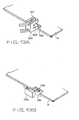
- Fig. 5 showing a plan view of medium sliding surface of the head assembly
- Fig. 8 showing a perspective view of core assembling portion of the head assembly.
- This embodiment realizes the writing and reading in track density of 48 TPI and 96 TPI in one head assembly.
- the head assembly comprises the writing/reading head core 21 set to the track width for 96 TPI, a pair of erasing head cores 23a, 23a energized at recording state of 96 TPI and 48 TPI, and a pair of erasing gaps 24a, 24a therefor.
- a pair of erasing head cores 23b, 23b are energized only at recording state of 48 TPI, and have a pair of erasing gaps 24b, 24b.
- the erasing head cores 23b, 23b are disposed outside the erasing head cores 23a, 23a as shown in Fig. 5.
- the writing/reading head core 21 is provided with a coil 24 and a closing core 30 adhered thereto, thus the magnetic circuit is constituted.
- a pair of head cores 23a, 23a are provided with an erasing coil 31 and a pair of closing coils 33, 33 adhered thereto, and a pair of the erasing head cores 23b, 23b are provided with an erasing coil 32 and a closing core 34 adhered thereto, thus respective magnetic circuits are constituted.
- the head assembly is moved and positioned in the direction of disc diameter by the stepping motor as track positioning mechanism.
- Fig. 9 is a diagram illustrating the writing/reading state by the head assembly as an embodiment of the invention.
- the head assembly is used for 96 TPI, since density of record data signal 35 . is high at the writing state as shown in Fig. 9(a), only a pair of erasing head cores 23a., 23a are operated and a pair of erasing head cores 23b, 23b outside the track are not energized in order to prevent the erasing head from erasing the adjacent data signal.
- the head assembly as an embodiment of the invention is used for 48 TPI
- two pairs of erasing head cores 23a, 23a, 23b, 23b are simultaneously energized at the writing state and written by the writing/reading head core 1 as shown in Fig. 9(b). If the information thus recorded is read out by an exclusive device for 48 TPI, output signal is decreased because of the narrowed track width in comparison to data signal recorded by the exclusive device for 48 TPI. But the output signal is sufficient as long as it is over a definite value.
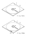
- Figs. 13A and 13B are schematic diagram illustrating the optical and mechanical means for detecting the notch as shown in Figs. 12A and 12B.
- an optical medium discrimination detector 10A comprises a light emitting diode 101 and a light receiving element 102 formed in a pair.
- the jacket 2 is inserted in a prescribed position, so that the notch 2A of the jacket 2 is not grasped at a position between the light emitting diode and the light receiving element.
- the jacket as shown in Fig. 12A without notch 2B for 48 TPI is shielded from the light thereby the light receiving element does not respond. If the jacket has the notch 2B the light receiving element acts in response to the light from the-light emitting diode and discriminates 96 TPI.
- a medium discrimination detector 10B comprises a microswitch.
- the jacket 2 is inserted in a prescribed position, so that the notch 2B is disposed to a sensor 105 of the medium discrimination detector 10B.
- the jacket as shown in Fig. 12A without notch 2B for 48 TPI pushes the sensor of the medium discrimination detector 10B comprising the microswitch, thereby the jacket is indicated as that for 48 TPI.
- the jacket for 96 TPI having the notch 2B is not inserted, the sensor is not pushed and the switch changing of the medium discrimination detector is not carried out, thereby the jacket is indicated as that for 96 TPI.
Landscapes
- Engineering & Computer Science (AREA)
- Manufacturing & Machinery (AREA)
- Digital Magnetic Recording (AREA)
Applications Claiming Priority (4)
| Application Number | Priority Date | Filing Date | Title |
|---|---|---|---|
| JP17306782A JPS5963018A (ja) | 1982-10-01 | 1982-10-01 | 磁気ヘツド組立体 |
| JP17306682A JPS5963016A (ja) | 1982-10-01 | 1982-10-01 | フレキシブルデイスク装置 |
| JP173066/82 | 1982-10-01 | ||
| JP173067/82 | 1982-10-01 |
Publications (2)
| Publication Number | Publication Date |
|---|---|
| EP0110050A1 true EP0110050A1 (fr) | 1984-06-13 |
| EP0110050B1 EP0110050B1 (fr) | 1988-06-01 |
Family
ID=26495193
Family Applications (1)
| Application Number | Title | Priority Date | Filing Date |
|---|---|---|---|
| EP83109589A Expired EP0110050B1 (fr) | 1982-10-01 | 1983-09-27 | Unité de disques pour disques souples à différentes largeurs de piste |
Country Status (3)
| Country | Link |
|---|---|
| US (1) | US4622601A (fr) |
| EP (1) | EP0110050B1 (fr) |
| DE (1) | DE3376903D1 (fr) |
Cited By (6)
| Publication number | Priority date | Publication date | Assignee | Title |
|---|---|---|---|---|
| EP0193044A1 (fr) * | 1985-02-27 | 1986-09-03 | Mitsubishi Denki Kabushiki Kaisha | Tête magnétique et procédé pour fabriquer celle-ci |
| EP0167826A3 (en) * | 1984-07-13 | 1987-08-19 | International Business Machines Corporation | Diskette drive and media type determination mechanism diskette drive and media type determination mechanism |
| EP0183412A3 (fr) * | 1984-11-15 | 1987-09-16 | Ing. C. Olivetti & C., S.p.A. | Appareil d'enregistrement et de reproduction de données sur un milieu d'enregistrement magnétique |
| EP0196605A3 (fr) * | 1985-03-30 | 1988-03-30 | Kabushiki Kaisha Toshiba | Assemblage de tête magnétique |
| US4814920A (en) * | 1984-07-10 | 1989-03-21 | Hitachi Maxell, Ltd. | Magnetic head with a slider |
| EP0484905A3 (en) * | 1990-11-09 | 1994-12-14 | Brier Technology | Interface for disk drives |
Families Citing this family (22)
| Publication number | Priority date | Publication date | Assignee | Title |
|---|---|---|---|---|
| JPH0782719B2 (ja) * | 1986-06-09 | 1995-09-06 | ティアツク株式会社 | 磁気デイスク装置 |
| JPH077485B2 (ja) * | 1986-06-16 | 1995-01-30 | ティアツク株式会社 | 磁気デイスク装置 |
| JPS63161508A (ja) * | 1986-12-25 | 1988-07-05 | Toshiba Corp | フロツピ−デイスク装置の磁気ヘツド装置 |
| JPH0711849B2 (ja) * | 1987-02-27 | 1995-02-08 | 株式会社東芝 | フロツピ−デイスク装置のデ−タ記録制御装置 |
| JPH03225676A (ja) * | 1990-01-31 | 1991-10-04 | Sony Corp | ディスク記録装置 |
| JPH04143911A (ja) * | 1990-10-05 | 1992-05-18 | Canon Electron Inc | 磁気ヘッド |
| IE922178A1 (en) * | 1991-07-19 | 1993-01-27 | Ian R O Rourke | Jacket for computer magnetic disk memory |
| JP3096951B2 (ja) * | 1994-12-09 | 2000-10-10 | アルプス電気株式会社 | 磁気記録再生装置 |
| WO2001082295A1 (fr) | 2000-04-20 | 2001-11-01 | Matsushita Electric Industrial Co., Ltd. | Unite de disque souple, procede de formatage de disque, et procede d'enregistrement/reproduction |
| US9601154B2 (en) | 2014-11-24 | 2017-03-21 | Seagate Technology Llc | Prioritized random access for magnetic recording |
| US9524743B2 (en) | 2014-11-24 | 2016-12-20 | Seagate Technology Llc | Heat assisted magnetic recording for bit-patterned media |
| US9747942B2 (en) | 2014-11-24 | 2017-08-29 | Seagate Technology Llc | Variable written track widths for attribute-based storage |
| US9324362B1 (en) | 2014-11-24 | 2016-04-26 | Seagate Technology Llc | Post-write scan operations for interlaced magnetic recording |
| US9773517B2 (en) | 2014-11-24 | 2017-09-26 | Seagate Technology Llc | Dual writer head design |
| US9842047B2 (en) | 2014-11-24 | 2017-12-12 | Seagate Technology Llc | Non-sequential write for sequential read back |
| US9508362B2 (en) | 2014-11-24 | 2016-11-29 | Seagate Technology Llc | Write management for interlaced magnetic recording devices |
| US9818445B2 (en) | 2016-01-12 | 2017-11-14 | Seagate Technology Llc | Magnetic storage device readers |
| US10210891B1 (en) | 2016-01-28 | 2019-02-19 | Seagate Technology Llc | Dual writer head design utilizing two writers of different sizes for writing interlaced data tracks |
| US9805741B1 (en) | 2016-01-29 | 2017-10-31 | Seagate Technology Llc | Write current parameter selection for magnetic recording |
| US9805744B1 (en) | 2016-04-01 | 2017-10-31 | Seagate Technology Llc | Dual writer design in interlaced magnetic recording |
| US9672851B1 (en) | 2016-05-04 | 2017-06-06 | Seagate Technology Llc | Single writer interlaced magnetic recording |
| US10199066B1 (en) | 2018-03-01 | 2019-02-05 | Seagate Technology Llc | Write management of physically coupled storage areas |
Citations (1)
| Publication number | Priority date | Publication date | Assignee | Title |
|---|---|---|---|---|
| US3353168A (en) * | 1964-04-09 | 1967-11-14 | Potter Instrument Co Inc | Wide-record narrow-read magnetic head |
Family Cites Families (5)
| Publication number | Priority date | Publication date | Assignee | Title |
|---|---|---|---|---|
| US3155949A (en) * | 1961-11-24 | 1964-11-03 | Ibm | Tunnel erase magnetic transducer |
| JPS539510A (en) * | 1976-07-14 | 1978-01-28 | Nippon Gakki Seizo Kk | Magnetic head |
| US4298897A (en) * | 1979-09-20 | 1981-11-03 | International Business Machines Corporation | Buffered recording |
| FR2478357A1 (fr) * | 1980-03-11 | 1981-09-18 | Lcc Cice Cie Europ Comp Electr | Tete magnetique d'enregistrement et de lecture de donnees magnetiques, a largeur de piste variable |
| US4371901A (en) * | 1980-10-16 | 1983-02-01 | Honeywell Inc. | Programmable signal equalizer |
-
1983
- 1983-09-27 DE DE8383109589T patent/DE3376903D1/de not_active Expired
- 1983-09-27 EP EP83109589A patent/EP0110050B1/fr not_active Expired
- 1983-09-30 US US06/537,439 patent/US4622601A/en not_active Expired - Lifetime
Patent Citations (1)
| Publication number | Priority date | Publication date | Assignee | Title |
|---|---|---|---|---|
| US3353168A (en) * | 1964-04-09 | 1967-11-14 | Potter Instrument Co Inc | Wide-record narrow-read magnetic head |
Non-Patent Citations (4)
| Title |
|---|
| DESIGN ENGINEERING, vol. 52, no. 5, May 1981, Waseca, USA N. SCLATER "The option of rotating disk memories", pages 41-44 * |
| IBM TECHNICAL DISCLOSURE BULLETIN, vol. 25, no. 2, July 1982, New York, USA C.M. CRUSE et al. "Universal flexible disk", page 468 * |
| Patent Abstracts of Japan Vol. 6, no. 229, 16 november 1982 & JP-A-57 130223 * |
| WIRELESS WORLD, vol. 88, no. 1561, October 1982, Olchester, GB J.R. WATKINSON "Floppy-disc drives", pages 80-82, 84 * |
Cited By (10)
| Publication number | Priority date | Publication date | Assignee | Title |
|---|---|---|---|---|
| US4814920A (en) * | 1984-07-10 | 1989-03-21 | Hitachi Maxell, Ltd. | Magnetic head with a slider |
| EP0167826A3 (en) * | 1984-07-13 | 1987-08-19 | International Business Machines Corporation | Diskette drive and media type determination mechanism diskette drive and media type determination mechanism |
| US4773036A (en) * | 1984-07-13 | 1988-09-20 | Ibm Corporation | Diskette drive and media type determination |
| EP0183412A3 (fr) * | 1984-11-15 | 1987-09-16 | Ing. C. Olivetti & C., S.p.A. | Appareil d'enregistrement et de reproduction de données sur un milieu d'enregistrement magnétique |
| US4805051A (en) * | 1984-11-15 | 1989-02-14 | Ing. C. Olivetti & C., S.P.A. | Apparatus for recording and reproducing data on a magnetic recording medium |
| EP0193044A1 (fr) * | 1985-02-27 | 1986-09-03 | Mitsubishi Denki Kabushiki Kaisha | Tête magnétique et procédé pour fabriquer celle-ci |
| US4745676A (en) * | 1985-02-27 | 1988-05-24 | Mitsubishi Denki Kabushiki Kaisha | Method for manufacturing a magnet head |
| EP0196605A3 (fr) * | 1985-03-30 | 1988-03-30 | Kabushiki Kaisha Toshiba | Assemblage de tête magnétique |
| EP0484905A3 (en) * | 1990-11-09 | 1994-12-14 | Brier Technology | Interface for disk drives |
| US5434722A (en) * | 1990-11-09 | 1995-07-18 | Brier Technology Inc. | Dual interface for disk drives |
Also Published As
| Publication number | Publication date |
|---|---|
| EP0110050B1 (fr) | 1988-06-01 |
| US4622601A (en) | 1986-11-11 |
| DE3376903D1 (en) | 1988-07-07 |
Similar Documents
| Publication | Publication Date | Title |
|---|---|---|
| US4622601A (en) | Flexible disc device for media of different track densities | |
| US4803571A (en) | Floppy disc magnetic head apparatus compatible with both horizontal and perpendicular recording media | |
| CA1147054A (fr) | Appareil d'enregistrement a memoire tampon | |
| CA1139436A (fr) | Dispositif de positionnement et formattage pour support a bande magnetique | |
| JP2728127B2 (ja) | コンピュータにおけるディスク・ドライブの電力消費量を削減し、データ転送を高速化する方法、および、コンピュータに接続されるディスク・ドライブ | |
| EP0139163B1 (fr) | Système pour transmettre des données comprenant plusieurs stations d'entrainement à disque | |
| US4984103A (en) | Method for reading/writing for a floppy disc drive with buffer memory | |
| JPS62121903A (ja) | 磁気記録媒体上のデ−タの記録・再生装置 | |
| CA2048075C (fr) | Appareil d'enregistrement et de lecture magnetiques pour le traitement des donnees et bande magnetique connexe | |
| US5329510A (en) | Method and apparatus for discriminating between unformatted magnetic disk assemblies of two different storage capacities | |
| US6324660B1 (en) | Defect management method for a magnetic recording medium | |
| US5822145A (en) | Information recording and/or reproducing apparatus using an information recording device having two kinds of recording media | |
| JPS6015880A (ja) | 記録媒体 | |
| GB2232808A (en) | Magnetic recording device | |
| US4876618A (en) | Method for detecting zero track | |
| US5353177A (en) | Method and apparatus for positioning a magnetic head unit on a track centerline | |
| JP3025561B2 (ja) | 光ディスク装置 | |
| US4849838A (en) | Large capacity information storage apparatus using a plurality of magnetic disk units | |
| JPH0524561B2 (fr) | ||
| KR100510450B1 (ko) | 복수의 하드디스크 어셈블리를 구비한 하드디스크 드라이브 | |
| US7099988B2 (en) | Apparatus and method to read information from an information storage medium | |
| JP3093808B2 (ja) | 情報記録再生装置 | |
| EP0572067B1 (fr) | Système d'enregistrement et/ou de lecture de signaux et cassette de rajustement convenant pour l'utilisation dans ce système | |
| JPH10293992A5 (fr) | ||
| JPS62128084A (ja) | 光デイスク |
Legal Events
| Date | Code | Title | Description |
|---|---|---|---|
| PUAI | Public reference made under article 153(3) epc to a published international application that has entered the european phase |
Free format text: ORIGINAL CODE: 0009012 |
|
| AK | Designated contracting states |
Designated state(s): DE FR GB |
|
| 17P | Request for examination filed |
Effective date: 19840509 |
|
| GRAA | (expected) grant |
Free format text: ORIGINAL CODE: 0009210 |
|
| AK | Designated contracting states |
Kind code of ref document: B1 Designated state(s): DE FR GB |
|
| REF | Corresponds to: |
Ref document number: 3376903 Country of ref document: DE Date of ref document: 19880707 |
|
| ET | Fr: translation filed | ||
| PLBE | No opposition filed within time limit |
Free format text: ORIGINAL CODE: 0009261 |
|
| STAA | Information on the status of an ep patent application or granted ep patent |
Free format text: STATUS: NO OPPOSITION FILED WITHIN TIME LIMIT |
|
| 26N | No opposition filed | ||
| PGFP | Annual fee paid to national office [announced via postgrant information from national office to epo] |
Ref country code: FR Payment date: 19920909 Year of fee payment: 10 |
|
| PG25 | Lapsed in a contracting state [announced via postgrant information from national office to epo] |
Ref country code: FR Free format text: LAPSE BECAUSE OF NON-PAYMENT OF DUE FEES Effective date: 19940531 |
|
| REG | Reference to a national code |
Ref country code: FR Ref legal event code: ST |
|
| REG | Reference to a national code |
Ref country code: GB Ref legal event code: 746 Effective date: 19950814 |
|
| PGFP | Annual fee paid to national office [announced via postgrant information from national office to epo] |
Ref country code: GB Payment date: 19981001 Year of fee payment: 16 |
|
| PGFP | Annual fee paid to national office [announced via postgrant information from national office to epo] |
Ref country code: DE Payment date: 19981005 Year of fee payment: 16 |
|
| PG25 | Lapsed in a contracting state [announced via postgrant information from national office to epo] |
Ref country code: GB Free format text: LAPSE BECAUSE OF NON-PAYMENT OF DUE FEES Effective date: 19990927 |
|
| GBPC | Gb: european patent ceased through non-payment of renewal fee |
Effective date: 19990927 |
|
| PG25 | Lapsed in a contracting state [announced via postgrant information from national office to epo] |
Ref country code: DE Free format text: LAPSE BECAUSE OF NON-PAYMENT OF DUE FEES Effective date: 20000701 |