EP0110094A1 - Bouton poussoir pour la fermeture de contacts électriques - Google Patents
Bouton poussoir pour la fermeture de contacts électriques Download PDFInfo
- Publication number
- EP0110094A1 EP0110094A1 EP83110388A EP83110388A EP0110094A1 EP 0110094 A1 EP0110094 A1 EP 0110094A1 EP 83110388 A EP83110388 A EP 83110388A EP 83110388 A EP83110388 A EP 83110388A EP 0110094 A1 EP0110094 A1 EP 0110094A1
- Authority
- EP
- European Patent Office
- Prior art keywords
- circuit board
- key
- housing
- printed circuit
- button
- Prior art date
- Legal status (The legal status is an assumption and is not a legal conclusion. Google has not performed a legal analysis and makes no representation as to the accuracy of the status listed.)
- Withdrawn
Links
- 239000004020 conductor Substances 0.000 claims abstract description 7
- 229920001971 elastomer Polymers 0.000 claims 1
- 239000000806 elastomer Substances 0.000 claims 1
- 238000009434 installation Methods 0.000 abstract 1
- 210000003128 head Anatomy 0.000 description 3
- 210000001331 nose Anatomy 0.000 description 3
- 229920003023 plastic Polymers 0.000 description 3
- 230000000694 effects Effects 0.000 description 2
- 230000003993 interaction Effects 0.000 description 2
- 239000000463 material Substances 0.000 description 2
- 238000010276 construction Methods 0.000 description 1
- 230000002950 deficient Effects 0.000 description 1
- 238000009429 electrical wiring Methods 0.000 description 1
- 238000005516 engineering process Methods 0.000 description 1
- 230000002349 favourable effect Effects 0.000 description 1
- 239000011888 foil Substances 0.000 description 1
- 230000037431 insertion Effects 0.000 description 1
- 238000003780 insertion Methods 0.000 description 1
- 238000004519 manufacturing process Methods 0.000 description 1
- 229920001296 polysiloxane Polymers 0.000 description 1
- 229910000679 solder Inorganic materials 0.000 description 1
- 238000005476 soldering Methods 0.000 description 1
Images
Classifications
-
- H—ELECTRICITY
- H01—ELECTRIC ELEMENTS
- H01H—ELECTRIC SWITCHES; RELAYS; SELECTORS; EMERGENCY PROTECTIVE DEVICES
- H01H13/00—Switches having rectilinearly-movable operating part or parts adapted for pushing or pulling in one direction only, e.g. push-button switch
- H01H13/70—Switches having rectilinearly-movable operating part or parts adapted for pushing or pulling in one direction only, e.g. push-button switch having a plurality of operating members associated with different sets of contacts, e.g. keyboard
- H01H13/702—Switches having rectilinearly-movable operating part or parts adapted for pushing or pulling in one direction only, e.g. push-button switch having a plurality of operating members associated with different sets of contacts, e.g. keyboard with contacts carried by or formed from layers in a multilayer structure, e.g. membrane switches
- H01H13/705—Switches having rectilinearly-movable operating part or parts adapted for pushing or pulling in one direction only, e.g. push-button switch having a plurality of operating members associated with different sets of contacts, e.g. keyboard with contacts carried by or formed from layers in a multilayer structure, e.g. membrane switches characterised by construction, mounting or arrangement of operating parts, e.g. push-buttons or keys
-
- H—ELECTRICITY
- H01—ELECTRIC ELEMENTS
- H01H—ELECTRIC SWITCHES; RELAYS; SELECTORS; EMERGENCY PROTECTIVE DEVICES
- H01H2215/00—Tactile feedback
- H01H2215/004—Collapsible dome or bubble
- H01H2215/012—Positioning of individual dome
-
- H—ELECTRICITY
- H01—ELECTRIC ELEMENTS
- H01H—ELECTRIC SWITCHES; RELAYS; SELECTORS; EMERGENCY PROTECTIVE DEVICES
- H01H2223/00—Casings
- H01H2223/054—Mounting of key housings on same printed circuit
-
- H—ELECTRICITY
- H01—ELECTRIC ELEMENTS
- H01H—ELECTRIC SWITCHES; RELAYS; SELECTORS; EMERGENCY PROTECTIVE DEVICES
- H01H2229/00—Manufacturing
- H01H2229/042—Snap coupling; Snap mounting
-
- H—ELECTRICITY
- H01—ELECTRIC ELEMENTS
- H01H—ELECTRIC SWITCHES; RELAYS; SELECTORS; EMERGENCY PROTECTIVE DEVICES
- H01H2233/00—Key modules
- H01H2233/03—Key modules mounted on support plate or frame
- H01H2233/034—Snap coupling
Definitions
- the invention relates to a key for closing electrical contacts with a push rod, which is displaceably mounted within a key housing, by pressing which the electrical contact is closed, and to a keyboard formed from a plurality of such keys.
- the present invention has for its object to provide a key or a keyboard that can be assembled in the simplest way and, if necessary, also dismantled again.
- the key housing simply has to be plugged onto the printed circuit board in order to form a finished key. After the contact surfaces have all been arranged on the side of the circuit board which serves as the carrier plate and faces the button housing, there is no need to solder the contacts from the other side of the circuit board.
- the conductor tracks and contact areas can be applied to carrier foils or the like, which are arranged between the key housing and the printed circuit board. According to an advantageous feature of the invention, however, the conductor tracks and the contact areas are preferably applied directly on one side of the circuit board.
- an additional switching contact surface is provided, which is arranged at a distance from the two contact surfaces and can be brought into contact with them by pressing the push-button plunger in order to produce the electrical contact.
- the additional switching contact surface is formed on a switching contact carrier part which rests on the printed circuit board and is held between the button housing and the printed circuit board when the push button housing is attached and locked.
- the switch contact carrier part expediently has a flat base part and an upwardly curved switch dome, which carries the switch contact surface on its upper inner surface, the switch dome being arranged within the button housing and the base part being clamped between the button housing and the printed circuit board.
- the switch contact carrier part only has to be placed on the circuit board to assemble the button and the button housing then has to be plugged onto the circuit board, the switch contact carrier part being automatically held in its desired position.
- the assembly of the button is further simplified if, according to a further feature of the invention, the push button plunger can be inserted into the button housing from the side facing away from the printed circuit board.
- an effective stop device is provided between the key housing and the push rod, which prevents the push rod from falling out of the push button housing when the push rod is inserted into the push button housing.
- the feeler plunger can have at least one leg resilient transversely to the actuation direction of the feeler plunger, the lower end of which has an outwardly projecting nose which interacts with a stop surface formed on the button housing. In order to facilitate the insertion of the push rod into the push button housing, it can also be advantageous if the lower, outer end of the leg is beveled.
- the button housing has resilient holding legs transverse to the actuating direction of the push button plunger, the free ends of which are provided with holding lugs on the other side of the Grasp the circuit board and hold the housing on the circuit board.
- the resilient retaining legs can have bevels at their lower ends, so that when the button housing is plugged onto the circuit board, the retaining legs are pressed resiliently to the side by running up the chamfers on one side wall of the circuit board until the retaining lugs snap under the other side of the circuit board .
- the button according to the invention is thus characterized by the simplest construction and extremely problem-free assembly.
- the button consists of only four parts, namely the circuit board serving as the carrier plate, the switch contact carrier part, the button housing and the push button plunger.
- the switch contact carrier part is placed on the circuit board, then the button housing is printed on the circuit board with the switch contact carrier part until the retaining legs snap into the back of the carrier plate, and finally the switch plunger is pressed into the button housing until the Snap the noses of the resilient legs behind the stop surface of the key housing. It is also particularly advantageous that the assembly can always be carried out from the same side of the carrier plate.
- the keys according to the invention can be used in conjunction with a keyboard, in which case a common circuit board is provided for all keys, which has a plurality of openings in the grid of the keyboard, via which the keys can be plugged onto the circuit board.
- the keys are arranged in one or more rows
- the keys Housing have two opposite support legs
- the key housings are arranged on the circuit board so that the support legs of two along a row of adjacent key housings face each other, with mutually facing support legs through each: a single opening in the circuit board.
- the switch contact surfaces are formed on at least one carrier mat, the switch contact surface carrier mats having openings whose grid corresponds to the grid of the openings in the printed circuit board, the openings of the carrier mat lying above the openings in the printed circuit board.
- the keyboard according to the invention is advantageously composed of a minimum of parts and can be assembled in the simplest way.
- the carrier plate that gives the keyboard mechanical stability also carries the electrical wiring pattern and the contact surfaces.
- the switch contact surface support mats only have to be placed on the circuit board in such a way that their two openings lie one above the other. Then the individual key housings are plugged onto the carrier plate, as a result of which the switch contact surface carrier mats are fixed in their position, and finally only the key plungers are still pressed into the key housing in the manner described above. Again, assembly can only be done from one side of the circuit board.
- the individual keys of the keyboard can be released from the printed circuit board in the simplest way, for example by compressing the holding legs, attached to another location on the keyboard, or used in another way.
- the keyboard according to the invention is therefore extremely versatile, universally applicable and offers great possibilities for variation.
- the individual keys can easily be used again, for example, in the event of a defective printed circuit board.
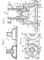
- the reference numeral 1 denotes a relatively rigid, rigid circuit board, which serves as a carrier plate for the button parts fastened thereon.
- the circuit board 1 is electrically insulating and has on its upper side 2 a plurality of electrically conductive conductor tracks (not shown), which have contact surfaces 3, 4 applied to the circuit board 1, of which only a single pair in FIG. 1 is shown, are electrically connected.
- the contact surfaces 3; 4 are arranged on the circuit board 1 in a certain grid, with each contact surface pair 3, 4 being assigned a key 5.
- a switch contact surface 7 is pressed down until it rests on the contact surfaces 3, 4 and bridges these two contact surfaces to establish electrical contact between the contact surfaces 3, 4.
- a switch contact surface 7 is pressed down until it rests on the contact surfaces 3, 4 and bridges these two contact surfaces to establish electrical contact between the contact surfaces 3, 4.
- several, for example four, electrically separate contact surfaces can also be provided in the switching region of one switching contact surface.
- a switch contact surface support mat 8 is arranged, which can in particular consist of silicone and is electrically insulating.
- the switch contact surface carrier mat 8 consists of a flat, flat base part 9, which rests on the top 2 of the printed circuit board 1, and a plurality of switch domes 10, which are designed like suction cups, which are open at the bottom and are provided with the electrically conductive switch contact surface 7 on their upper inside are.
- the switching dome 10 is provided with an upper lifting element 11, the base part 9, the switching dome 10 and the overstroke element 11 being formed in one piece.
- the switching dome 10 together with the upper lifting element 11 is arranged on the circuit board 1 in such a way that the switching contact surface 7 lies opposite the contact surface pair 3, 4.
- the circuit board 1 has a plurality of openings 12, with each key 5 being assigned two openings 12.
- the openings 12 are arranged on the printed circuit board 1 at regular intervals, which correspond to the grid of the keyboard, the contact surface pairs 3, 4 being located approximately in the middle between two openings 12.
- the switch contact surface carrier mats 8 likewise have openings 13 on their base part 9, the shape and the mutual spacing of which corresponds to the shape and the mutual spacing of the openings 12.
- the carrier mat 8 is placed on the circuit board 1 so that the openings 12 and 13 are located one above the other.
- a button housing 14 of essentially rectangular cross section is placed on the circuit board 1 above each pair of contact surfaces 3, 4 or above each switching dome 10.
- the button housing 14 is open on its underside facing the printed circuit board 1.
- a guide shaft 16 with a rectangular cross section is formed on the ceiling 15 of the key housing 14, the cross-sectional area of which is smaller than the cross-sectional area of the lower region of the key housing 14.
- the two side walls of the key housing 14 lying parallel to the plane of the drawing are supported on the upper side 2 of the printed circuit board 1.
- the two side walls of the key housing 14, which are perpendicular to the plane of the drawing, are designed as holding legs 17 which are molded onto the key housing 14 at their upper region, but are otherwise not connected to the key housing, so that, due to the elasticity of the plastic material of the key housing 14 or the holding legs 17 a resilient deformation of the holding legs 17, in particular their lower ends, is possible transversely to the direction of arrow A.
- the holding legs 17 each extend through an opening 12 and serve to hold the key housing 14 on the printed circuit board 1. For this purpose, they are longer than the side walls of the key housing 14 lying parallel to the plane of the drawing and each point inwards at their lower ends directed retaining lug 18, which engage on the lower side 19 of the circuit board 1 and thereby hold or lock the button housing 14 on the circuit board 1.
- the inner, mutually facing side surfaces of the retaining lugs 18 have bevels 20, which have the effect that, when the button housing 14 is plugged onto the printed circuit board 1, the holding legs 17 are automatically pushed apart by the interaction of the bevels 20 with the inner sides of the openings 12 to be facing one another until the button housing 14 is complete is placed on the circuit board, ie until they parallel to the drawing level.
- the push rod 6 comprises a guide part 21 of essentially rectangular cross section, the outer dimensions of which are adapted to the inner cross section of the guide shaft 16 of the push button housing 14, so that the push rod 6 is displaceably mounted in the push button housing 14 in the direction of arrow A.
- the tappet 6 At its upper end, the tappet 6 carries a widened head 22, the lower side of which forms a lower stop for the tappet 6 by interaction with the upper end of the guide shaft 16.
- a transparent plastic cap can be placed on the head 22 of the tappet 6, the upper side of which can be provided with a tactile recess in an ergonomically advantageous manner, with a labeled or inscribable leaflet can be inserted, which serves to identify or designate the button.
- the top of the head 22 itself can serve as a tactile surface, in which case it preferably has a tactile depression itself.
- the two side walls of the push button plunger 6, which are parallel to the plane of the drawing, are also essentially rigid in the case of the push button 6, while the side walls perpendicular to this are formed in their lower regions as resilient legs 23, which are arranged on their upper part Are molded on the area of the push rod and due to the elasticity of the plastic material of the push rod are resilient at least in their lower region transverse to direction A.
- the two legs 23 each have at their lower ends an outwardly projecting nose 24 which interacts with the lower inner edge 25 of the ceiling 15 of the key housing 14, so that the upper stop of the push rod 6 is thereby defined.
- the outer sides of the lugs 24 facing away from one another have bevels 26 which cause the legs 23 to be compressed when the push-button plunger is inserted into the push-button housing.
- the legs 23 snap outwards into the position shown in FIG. 1, as a result of which the push rod is held securely on the push button housing 4.
- a stop surface 27 Arranged in the interior of the push rod 6 is a stop surface 27 which is fixedly connected to the push rod 6 and which is connected to the upper end of the upper lifting element 11 cooperates. Due to the elasticity of the upper stroke element 11 or the switching dome 10, the push rod 6 is shown in FIG. 1.
- buttons are applied to the printed circuit board 1 in the desired key pattern.
- a separate switch contact surface support mat 8 is provided for each row of buttons.
- the lateral projections 28 of the carrier mat 8 serve for more precise positioning and holding of the key mat 8 and correspond in their shape to corresponding recesses on the lower edge of the side walls of the key housing, not shown, which lie parallel to the drawing plane according to FIG. 1.
- the above-described keyboard is assembled in a very simple manner: First, the switching contact surface carrier mat 8 (or several thereof) is placed on the printed circuit board 1 such that the openings 13 match the openings 12. The individual key housings 14 are then pressed into their respective desired positions. Finally, the push button 2 is pressed into the guide shaft 16 of the button housing 14.
- buttons are also very easy. For this purpose, only the push rod 6 has to be pulled out of the push button housing while overcoming the latching force of the legs 23 or the lugs 24 and the holding legs 17 have to be spread outwards from the back of the printed circuit board 1 so that the push button housing 14 is lifted upwards can. Of course, you can also proceed in reverse order.
Landscapes
- Push-Button Switches (AREA)
Applications Claiming Priority (2)
| Application Number | Priority Date | Filing Date | Title |
|---|---|---|---|
| DE3240940 | 1982-11-05 | ||
| DE19823240940 DE3240940A1 (de) | 1982-11-05 | 1982-11-05 | Taste zum schliessen elektrischer kontakte |
Publications (1)
| Publication Number | Publication Date |
|---|---|
| EP0110094A1 true EP0110094A1 (fr) | 1984-06-13 |
Family
ID=6177401
Family Applications (1)
| Application Number | Title | Priority Date | Filing Date |
|---|---|---|---|
| EP83110388A Withdrawn EP0110094A1 (fr) | 1982-11-05 | 1983-10-18 | Bouton poussoir pour la fermeture de contacts électriques |
Country Status (2)
| Country | Link |
|---|---|
| EP (1) | EP0110094A1 (fr) |
| DE (1) | DE3240940A1 (fr) |
Cited By (6)
| Publication number | Priority date | Publication date | Assignee | Title |
|---|---|---|---|---|
| EP0461529A3 (en) * | 1990-06-11 | 1992-08-05 | Fujitsu Limited | Push switch with improved actuator assembly |
| GB2264393A (en) * | 1992-02-22 | 1993-08-25 | Mckechnie Uk Ltd | Keyboard |
| GB2271023A (en) * | 1992-09-24 | 1994-03-30 | Txc Corp | Direction controller for a video game. |
| FR2803084A1 (fr) * | 1999-12-27 | 2001-06-29 | Itt Mfg Entpr S Inc | Commutateur electrique a effet tactile fixe par emboitement elastique sur une plaque a circuits |
| WO2008009243A1 (fr) * | 2006-07-17 | 2008-01-24 | Siemens Aktiengesellschaft | Poussoir servant à actionner un élément de commutation |
| EP1837888A3 (fr) * | 2006-03-22 | 2009-03-25 | TRW Automotive Electronics & Components GmbH & Co. KG | Module de commutateur |
Families Citing this family (2)
| Publication number | Priority date | Publication date | Assignee | Title |
|---|---|---|---|---|
| DE4307613C2 (de) * | 1993-03-06 | 1996-03-28 | Deutsche Telephonwerk Kabel | Anordnung für Tastaturen von Kommunikations-Endgeräten |
| DE19541380A1 (de) * | 1995-11-07 | 1997-05-15 | Teves Gmbh Alfred | Schalter mit auf die Leiterplatte aufgerasteten Schaltmodulen |
Citations (3)
| Publication number | Priority date | Publication date | Assignee | Title |
|---|---|---|---|---|
| US3900712A (en) * | 1973-02-23 | 1975-08-19 | Brother Ind Ltd | Keyboard switch arrangement |
| US3917917A (en) * | 1973-08-23 | 1975-11-04 | Alps Electric Co Ltd | Keyboard pushbutton switch assembly having multilayer contact and circuit structure |
| GB2046996A (en) * | 1979-04-11 | 1980-11-19 | Electronic Components Ltd | Electrical switch |
-
1982
- 1982-11-05 DE DE19823240940 patent/DE3240940A1/de not_active Ceased
-
1983
- 1983-10-18 EP EP83110388A patent/EP0110094A1/fr not_active Withdrawn
Patent Citations (3)
| Publication number | Priority date | Publication date | Assignee | Title |
|---|---|---|---|---|
| US3900712A (en) * | 1973-02-23 | 1975-08-19 | Brother Ind Ltd | Keyboard switch arrangement |
| US3917917A (en) * | 1973-08-23 | 1975-11-04 | Alps Electric Co Ltd | Keyboard pushbutton switch assembly having multilayer contact and circuit structure |
| GB2046996A (en) * | 1979-04-11 | 1980-11-19 | Electronic Components Ltd | Electrical switch |
Cited By (11)
| Publication number | Priority date | Publication date | Assignee | Title |
|---|---|---|---|---|
| EP0461529A3 (en) * | 1990-06-11 | 1992-08-05 | Fujitsu Limited | Push switch with improved actuator assembly |
| GB2264393A (en) * | 1992-02-22 | 1993-08-25 | Mckechnie Uk Ltd | Keyboard |
| EP0558239A1 (fr) * | 1992-02-22 | 1993-09-01 | McKechnie UK Limited | Commutateur à bouton-poussoirs |
| GB2271023A (en) * | 1992-09-24 | 1994-03-30 | Txc Corp | Direction controller for a video game. |
| FR2803084A1 (fr) * | 1999-12-27 | 2001-06-29 | Itt Mfg Entpr S Inc | Commutateur electrique a effet tactile fixe par emboitement elastique sur une plaque a circuits |
| WO2001048770A1 (fr) * | 1999-12-27 | 2001-07-05 | Itt Manufacturing Enterprises Inc. | Commutateur electrique individuel etanche fixe par emboîtement sur une plaque a circuits |
| US6501036B2 (en) | 1999-12-27 | 2002-12-31 | Itt Manufacturing Enterprises, Inc. | Sealed board-mounted electrical switch |
| EP1837888A3 (fr) * | 2006-03-22 | 2009-03-25 | TRW Automotive Electronics & Components GmbH & Co. KG | Module de commutateur |
| US7638724B2 (en) | 2006-03-22 | 2009-12-29 | Trw Automotive Electronics & Components Gmbh & Co. Kg | Switch module |
| WO2008009243A1 (fr) * | 2006-07-17 | 2008-01-24 | Siemens Aktiengesellschaft | Poussoir servant à actionner un élément de commutation |
| CN101438362B (zh) * | 2006-07-17 | 2013-02-20 | 西门子公司 | 用于操纵开关元件的挺杆 |
Also Published As
| Publication number | Publication date |
|---|---|
| DE3240940A1 (de) | 1984-05-10 |
Similar Documents
| Publication | Publication Date | Title |
|---|---|---|
| DE2235860C3 (de) | Steuergerät mit mindestens einer elektrischen Kontaktsteuervorrichtung | |
| DE3019886A1 (de) | Fluessigkeits- und gasdichter schiebeschalter | |
| DE8302660U1 (de) | Tastenanordnung zur Auslösung von bestimmten Symbolen der Tastenoberfläche jeweils zugeordneten Schaltfunktionen oder Schaltsignalen. | |
| EP0163874A2 (fr) | Commutateur à touche | |
| DE60101520T2 (de) | Tastschalter mit Tastenkopf welcher auf- und abbewegbar ist und Verfahren zu seiner Herstellung | |
| DE2515185B2 (de) | Elektrischer Schnappschalter | |
| DE2301853C3 (de) | Tastschalter | |
| EP0110094A1 (fr) | Bouton poussoir pour la fermeture de contacts électriques | |
| DE2943855A1 (de) | Drucktaste | |
| DE2951327A1 (de) | Hermetisch dichte schaltervorrichtung | |
| DE2531841C3 (de) | Elektrischer Schnappschalter | |
| DE3941712A1 (de) | Drucktastenanordnung | |
| DE2705756C2 (de) | Druckknopfschalter für elektronische Tischrechner o.dgl. | |
| DE2524287A1 (de) | Elektrischer schalter | |
| DE2950665A1 (de) | Tastwahlblock fuer fernsprechgeraete | |
| CH652269A5 (en) | Quick mounting base made of plastic, for fixing an electrical device or printed-circuit board | |
| DE2516527A1 (de) | Aus einzelnen leuchttastern zusammengesetzte tastatur | |
| EP0678885A1 (fr) | Touche électrique | |
| DE29820853U1 (de) | Tastenkappe | |
| DE2826262A1 (de) | Tastenbrett mit drucktasten zur alphanumerischen steuerung fuer eine elektrische oder elektronische maschine | |
| DE19836793C2 (de) | Bedienelement zum selektiven Herstellen elektrischer Kontakte | |
| DE2730659C2 (de) | Tastschalter | |
| DE2462035C3 (de) | Tastatur | |
| DE2830661C2 (de) | Schalteinrichtung für elektrische Geräte | |
| DE3107440A1 (de) | Elektrischer schalter, insbesondere zur anordnung im schalthebelende eines lenkstockschalters |
Legal Events
| Date | Code | Title | Description |
|---|---|---|---|
| PUAI | Public reference made under article 153(3) epc to a published international application that has entered the european phase |
Free format text: ORIGINAL CODE: 0009012 |
|
| AK | Designated contracting states |
Designated state(s): DE FR GB IT |
|
| STAA | Information on the status of an ep patent application or granted ep patent |
Free format text: STATUS: THE APPLICATION HAS BEEN WITHDRAWN |
|
| 18W | Application withdrawn |
Withdrawal date: 19840607 |
|
| RIN1 | Information on inventor provided before grant (corrected) |
Inventor name: DAETZL, ALFRED |