EP0110095A1 - Générateur de consigne pour un dispositif de régulation d'entraînement - Google Patents
Générateur de consigne pour un dispositif de régulation d'entraînement Download PDFInfo
- Publication number
- EP0110095A1 EP0110095A1 EP19830110412 EP83110412A EP0110095A1 EP 0110095 A1 EP0110095 A1 EP 0110095A1 EP 19830110412 EP19830110412 EP 19830110412 EP 83110412 A EP83110412 A EP 83110412A EP 0110095 A1 EP0110095 A1 EP 0110095A1
- Authority
- EP
- European Patent Office
- Prior art keywords
- setpoint
- input
- clock
- output
- generator
- Prior art date
- Legal status (The legal status is an assumption and is not a legal conclusion. Google has not performed a legal analysis and makes no representation as to the accuracy of the status listed.)
- Granted
Links
Images

Classifications
-
- G—PHYSICS
- G05—CONTROLLING; REGULATING
- G05B—CONTROL OR REGULATING SYSTEMS IN GENERAL; FUNCTIONAL ELEMENTS OF SUCH SYSTEMS; MONITORING OR TESTING ARRANGEMENTS FOR SUCH SYSTEMS OR ELEMENTS
- G05B19/00—Program-control systems
- G05B19/02—Program-control systems electric
- G05B19/18—Numerical control [NC], i.e. automatically operating machines, in particular machine tools, e.g. in a manufacturing environment, so as to execute positioning, movement or co-ordinated operations by means of program data in numerical form
- G05B19/19—Numerical control [NC], i.e. automatically operating machines, in particular machine tools, e.g. in a manufacturing environment, so as to execute positioning, movement or co-ordinated operations by means of program data in numerical form characterised by positioning or contouring control systems, e.g. to control position from one programmed point to another or to control movement along a programmed continuous path
- G05B19/21—Numerical control [NC], i.e. automatically operating machines, in particular machine tools, e.g. in a manufacturing environment, so as to execute positioning, movement or co-ordinated operations by means of program data in numerical form characterised by positioning or contouring control systems, e.g. to control position from one programmed point to another or to control movement along a programmed continuous path using an incremental digital measuring device
- G05B19/23—Numerical control [NC], i.e. automatically operating machines, in particular machine tools, e.g. in a manufacturing environment, so as to execute positioning, movement or co-ordinated operations by means of program data in numerical form characterised by positioning or contouring control systems, e.g. to control position from one programmed point to another or to control movement along a programmed continuous path using an incremental digital measuring device for point-to-point control
- G05B19/231—Numerical control [NC], i.e. automatically operating machines, in particular machine tools, e.g. in a manufacturing environment, so as to execute positioning, movement or co-ordinated operations by means of program data in numerical form characterised by positioning or contouring control systems, e.g. to control position from one programmed point to another or to control movement along a programmed continuous path using an incremental digital measuring device for point-to-point control the positional error is used to control continuously the servomotor according to its magnitude
- G05B19/232—Numerical control [NC], i.e. automatically operating machines, in particular machine tools, e.g. in a manufacturing environment, so as to execute positioning, movement or co-ordinated operations by means of program data in numerical form characterised by positioning or contouring control systems, e.g. to control position from one programmed point to another or to control movement along a programmed continuous path using an incremental digital measuring device for point-to-point control the positional error is used to control continuously the servomotor according to its magnitude with speed feedback only
-
- B—PERFORMING OPERATIONS; TRANSPORTING
- B66—HOISTING; LIFTING; HAULING
- B66B—ELEVATORS; ESCALATORS OR MOVING WALKWAYS
- B66B1/00—Control systems of elevators in general
- B66B1/24—Control systems with regulation, i.e. with retroactive action, for influencing travelling speed, acceleration, or deceleration
- B66B1/28—Control systems with regulation, i.e. with retroactive action, for influencing travelling speed, acceleration, or deceleration electrical
- B66B1/285—Control systems with regulation, i.e. with retroactive action, for influencing travelling speed, acceleration, or deceleration electrical with the use of a speed pattern generator
-
- G—PHYSICS
- G05—CONTROLLING; REGULATING
- G05B—CONTROL OR REGULATING SYSTEMS IN GENERAL; FUNCTIONAL ELEMENTS OF SUCH SYSTEMS; MONITORING OR TESTING ARRANGEMENTS FOR SUCH SYSTEMS OR ELEMENTS
- G05B2219/00—Program-control systems
- G05B2219/30—Nc systems
- G05B2219/34—Director, elements to supervisory
- G05B2219/34188—Safety, stop, slowdown interpolator if speed, position, torque error too large
-
- G—PHYSICS
- G05—CONTROLLING; REGULATING
- G05B—CONTROL OR REGULATING SYSTEMS IN GENERAL; FUNCTIONAL ELEMENTS OF SUCH SYSTEMS; MONITORING OR TESTING ARRANGEMENTS FOR SUCH SYSTEMS OR ELEMENTS
- G05B2219/00—Program-control systems
- G05B2219/30—Nc systems
- G05B2219/43—Speed, acceleration, deceleration control ADC
- G05B2219/43047—If speed below reference, small acceleration, if above, large deceleration
-
- H—ELECTRICITY
- H02—GENERATION; CONVERSION OR DISTRIBUTION OF ELECTRIC POWER
- H02P—CONTROL OR REGULATION OF ELECTRIC MOTORS, ELECTRIC GENERATORS OR DYNAMO-ELECTRIC CONVERTERS; CONTROLLING TRANSFORMERS, REACTORS OR CHOKE COILS
- H02P21/00—Arrangements or methods for the control of electric machines by vector control, e.g. by control of field orientation
Definitions
- the invention relates to a setpoint generator for a drive control device, the setpoint generator having a control memory in which at least permissible jerk values and limit values of the acceleration are stored and which is connected to a setpoint clock generator and three integrators for the formation of the acceleration, the speed and the path, and wherein when the clock signals generated by the setpoint clock generator occur, the output variable of the third integrator is fed to a position control loop of the drive control device as a position setpoint.
- the control memory consists of a programmable read-only memory, that of the clock generator of a digital computer via a Frequency divider setpoint clock signals are supplied.
- the setpoint clock signals appear, the assigned jerk values are called up and, taking the acceleration limit values into account, displacement setpoints are generated by numerical integration.
- driving curves can be generated, for example, in passenger elevators, by means of which optimal results can be achieved in terms of driving comfort and the duration of a journey.
- the setpoint generator according to the preamble in the upper speed Adjust the range to the ramp-up characteristic of the motor, so that the control over the entire speed range is guaranteed.
- the invention proposes, as characterized in the claims, to monitor the control deviation in such a way that when the largest control deviation associated with the full control of the actuators is exceeded, the clock frequency of the setpoint generator is reduced proportionally to the overshoot.
- the setpoints are fed to the control circuit at correspondingly larger time intervals until the greatest control deviation is undershot, whereupon the setpoint generator continues to work with the original clock frequency.
- the actual speed value generator 3 is coupled to the electric motor 1 and connected to a first subtractor 9 for the formation of the speed control deviation ⁇ v.
- the travel actual value encoder 4 is on a second subtractor 10 for the Formation of the path control deviation As connected and connected to the load 2 in such a way that changes in position can be detected immediately.
- the electric motor 1 can be an asynchronous motor, for example, the actuator 7 consisting of thyristors controlled in the stator circuit and controlled by means of ignition angle adjustment.
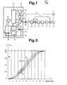
- the setpoint generator 8 consists of a control memory 11, three integrators 12, 13, 14 generating the acceleration s, the speed s and the path s s , a correction element 15 and a setpoint clock 16, for example in the form of a function generator with a controllable frequency. Permissible jerk values and limit values of the acceleration and speed are stored in the control memory 11, the jerk values being fed to the first integrator 12 and the generated acceleration and speed values being fed back to the control memory 11 for comparison with the limit values.
- the output of the third integrator 14 is connected to the second subtractor 10 for the formation of the displacement control deviation As.
- a limit value As' of the displacement control deviation is stored in the control memory 11, which corresponds to the largest displacement control deviation present when the thyristors of the actuator 7 are fully controlled, and which is fed to an input of a subtractor 17 and an input of a divider 18 of the correction element 15.
- the other input of divider 18 is connected to the output of the subtractor 17, the second input of which is connected to the output of the subtractor 10 for the formation of the displacement control deviation As.
- the correction element 15 also has a multiplier 19 and an adder 20, the one input of the multiplier 19 being connected to the output of the divider 18 and the other input being connected to an input of the adder 20 and the latter two inputs having the time T 0 of a period of Clock signals, for example in the form of a constant voltage is supplied.
- the output of the multiplier 19 is connected to the other input of the adder 20, the output of which is connected to the input of the setpoint clock 16.
- the setpoint generator 8 as well as the controllers 5, 6 and the subtractors 9, 10 are integrated in a microcomputer system, the control memory 11 being a programmable read-only memory and the functions of the integrators 12, 13, 14, the correction element 15 and the subtractors 9, 10 are executed by the computing unit of a microprocessor.
- This percentage deviation is fed to the multiplier 19, by means of which a time deviation t is formed by multiplication by the time T o of a setpoint cycle.
- a travel setpoint characteristic curve s' is generated, which is adapted to the travel actual value characteristic curve s i in such a way that control over the entire speed range is ensured.
- Consisting of the Wegsoll- or actual values Wegregelabweichungs characteristic .DELTA.s formed is preset for the drive as the driving curve v ', where according to FIG.
Landscapes
- Engineering & Computer Science (AREA)
- Automation & Control Theory (AREA)
- Human Computer Interaction (AREA)
- Manufacturing & Machinery (AREA)
- Physics & Mathematics (AREA)
- General Physics & Mathematics (AREA)
- Control Of Electric Motors In General (AREA)
- Control Of Position Or Direction (AREA)
- Elevator Control (AREA)
- Non-Reversible Transmitting Devices (AREA)
- Networks Using Active Elements (AREA)
Priority Applications (1)
| Application Number | Priority Date | Filing Date | Title |
|---|---|---|---|
| AT83110412T ATE21089T1 (de) | 1982-11-19 | 1983-10-19 | Sollwertgeber fuer eine antriebsregelungseinrichtung. |
Applications Claiming Priority (2)
| Application Number | Priority Date | Filing Date | Title |
|---|---|---|---|
| CH6740/82A CH663778A5 (de) | 1982-11-19 | 1982-11-19 | Sollwertgeber fuer eine antriebsregelungseinrichtung. |
| CH6740/82 | 1982-11-19 |
Publications (2)
| Publication Number | Publication Date |
|---|---|
| EP0110095A1 true EP0110095A1 (fr) | 1984-06-13 |
| EP0110095B1 EP0110095B1 (fr) | 1986-07-30 |
Family
ID=4314275
Family Applications (1)
| Application Number | Title | Priority Date | Filing Date |
|---|---|---|---|
| EP19830110412 Expired EP0110095B1 (fr) | 1982-11-19 | 1983-10-19 | Générateur de consigne pour un dispositif de régulation d'entraînement |
Country Status (7)
| Country | Link |
|---|---|
| US (1) | US4518909A (fr) |
| EP (1) | EP0110095B1 (fr) |
| AT (1) | ATE21089T1 (fr) |
| CA (1) | CA1203604A (fr) |
| CH (1) | CH663778A5 (fr) |
| DE (1) | DE3364997D1 (fr) |
| FI (1) | FI84464C (fr) |
Cited By (2)
| Publication number | Priority date | Publication date | Assignee | Title |
|---|---|---|---|---|
| EP0773180A1 (fr) | 1995-11-08 | 1997-05-14 | Inventio Ag | Procédé et dispositif pour augmenter la sécurité des ascenseurs |
| EP1621507A4 (fr) * | 2003-02-25 | 2011-07-06 | Mitsubishi Electric Corp | Limiteur de vitesse pour ascenseur |
Families Citing this family (5)
| Publication number | Priority date | Publication date | Assignee | Title |
|---|---|---|---|---|
| KR910005243B1 (ko) * | 1988-12-30 | 1991-07-24 | 삼성전자 주식회사 | 지수함수적 가감속에 의한 서보모터의 위치제어장치 및 방법 |
| SE461383B (sv) * | 1989-01-11 | 1990-02-12 | Inst Mash Im A Ablagonravova A | Foerfarande foer styrning av en s k mekanisk resonanshand |
| US4985668A (en) * | 1989-09-19 | 1991-01-15 | Kabushiki Kaisha Kobe Seiko Sho | Robot controller |
| JPH0916241A (ja) * | 1995-06-29 | 1997-01-17 | Fanuc Ltd | ロボットの加減速動作の設定方法 |
| DE19848681C2 (de) * | 1998-10-22 | 2002-04-11 | Boy Gmbh Dr | Auswerfer für eine Spritzgießmaschine |
Citations (6)
| Publication number | Priority date | Publication date | Assignee | Title |
|---|---|---|---|---|
| DE1186184B (de) * | 1961-06-24 | 1965-01-28 | Siemens Ag | Geschwindigkeits-Sollwertgeber fuer Treibscheibenfoerdermaschinen |
| CH424935A (de) * | 1964-02-07 | 1966-11-30 | Tos Kurim Narodui Podnik | Verfahren zum Steuern des Vorschubes an Werkzeugmaschinen durch einen Steuerzähler |
| US3428792A (en) * | 1965-06-21 | 1969-02-18 | Gen Electric | Velocity control system |
| US3911347A (en) * | 1972-02-20 | 1975-10-07 | Xenex Corp | Adaptive control system |
| US3941987A (en) * | 1973-09-04 | 1976-03-02 | Danly Machine Corporation | Method and apparatus for numerical control |
| EP0026406A1 (fr) * | 1979-09-27 | 1981-04-08 | Inventio Ag | Commande d'entraînement pour un ascenseur |
Family Cites Families (3)
| Publication number | Priority date | Publication date | Assignee | Title |
|---|---|---|---|---|
| US3665493A (en) * | 1970-03-30 | 1972-05-23 | Bendix Corp | Adaptive numerical control system for a machine tool |
| US4025837A (en) * | 1975-06-30 | 1977-05-24 | International Business Machines Corporation | Adaptive control circuit for a stepping motor |
| US4161013A (en) * | 1977-05-23 | 1979-07-10 | Massachusetts Institute Of Technology | Electromechanochemical device |
-
1982
- 1982-11-19 CH CH6740/82A patent/CH663778A5/de not_active IP Right Cessation
-
1983
- 1983-10-19 EP EP19830110412 patent/EP0110095B1/fr not_active Expired
- 1983-10-19 DE DE8383110412T patent/DE3364997D1/de not_active Expired
- 1983-10-19 AT AT83110412T patent/ATE21089T1/de active
- 1983-11-08 CA CA000440702A patent/CA1203604A/fr not_active Expired
- 1983-11-14 US US06/551,319 patent/US4518909A/en not_active Expired - Fee Related
- 1983-11-15 FI FI834173A patent/FI84464C/fi not_active IP Right Cessation
Patent Citations (6)
| Publication number | Priority date | Publication date | Assignee | Title |
|---|---|---|---|---|
| DE1186184B (de) * | 1961-06-24 | 1965-01-28 | Siemens Ag | Geschwindigkeits-Sollwertgeber fuer Treibscheibenfoerdermaschinen |
| CH424935A (de) * | 1964-02-07 | 1966-11-30 | Tos Kurim Narodui Podnik | Verfahren zum Steuern des Vorschubes an Werkzeugmaschinen durch einen Steuerzähler |
| US3428792A (en) * | 1965-06-21 | 1969-02-18 | Gen Electric | Velocity control system |
| US3911347A (en) * | 1972-02-20 | 1975-10-07 | Xenex Corp | Adaptive control system |
| US3941987A (en) * | 1973-09-04 | 1976-03-02 | Danly Machine Corporation | Method and apparatus for numerical control |
| EP0026406A1 (fr) * | 1979-09-27 | 1981-04-08 | Inventio Ag | Commande d'entraînement pour un ascenseur |
Cited By (3)
| Publication number | Priority date | Publication date | Assignee | Title |
|---|---|---|---|---|
| EP0773180A1 (fr) | 1995-11-08 | 1997-05-14 | Inventio Ag | Procédé et dispositif pour augmenter la sécurité des ascenseurs |
| US5869794A (en) * | 1995-11-08 | 1999-02-09 | Inventio Ag | Method and device for increased safety in elevators |
| EP1621507A4 (fr) * | 2003-02-25 | 2011-07-06 | Mitsubishi Electric Corp | Limiteur de vitesse pour ascenseur |
Also Published As
| Publication number | Publication date |
|---|---|
| FI834173A0 (fi) | 1983-11-15 |
| CH663778A5 (de) | 1988-01-15 |
| US4518909A (en) | 1985-05-21 |
| FI834173L (fi) | 1984-05-20 |
| FI84464B (fi) | 1991-08-30 |
| DE3364997D1 (en) | 1986-09-04 |
| CA1203604A (fr) | 1986-04-22 |
| EP0110095B1 (fr) | 1986-07-30 |
| FI84464C (fi) | 1991-12-10 |
| ATE21089T1 (de) | 1986-08-15 |
Similar Documents
| Publication | Publication Date | Title |
|---|---|---|
| DE2715408C2 (de) | Verfahren zum Betrieb und Regeleinrichtung für eine Brennkraftmaschine zum Konstanthalten wählbarer Drehzahlen | |
| DE69007866T2 (de) | Anlage, um eine Pumpvorrichtung zu steuern. | |
| DE169693T1 (de) | Automatisches geschwindigkeitsregelsystem. | |
| EP0110095B1 (fr) | Générateur de consigne pour un dispositif de régulation d'entraînement | |
| DE3886394T2 (de) | Verfahren zur steuerung eines servomotors. | |
| EP0103133B1 (fr) | Dispositif de réglage pour convertisseurs de courant | |
| DE3343883A1 (de) | Verfahren und einrichtung zur zweipunktregelung eines laststromes | |
| DE2231948C2 (de) | Drehzahl-Regelvorrichtung für einen Antriebsmotor eines Fahrzeugs | |
| DE3243549A1 (de) | Regelvorrichtung fuer die volldigitalisierte drehzahlreglung einer naehmaschine bzw. eines naehautomaten | |
| DE2755202A1 (de) | Verfahren zur einstellung des schaltrucks in kraftfahrzeugen | |
| DE3001778C2 (de) | Verfahren und Einrichtung zur Wegregelung eines Positionsantriebes | |
| DE2816613A1 (de) | Einrichtung zum regeln der fahrgeschwindigkeit eines kraftfahrzeugs | |
| DE2239897A1 (de) | Einrichtung zur drehzahlregelung eines asynchronmotors | |
| EP0440868B1 (fr) | Régulation pour la commande du basculement d'un convertisseur à plusieurs moteurs | |
| DE4410959C2 (de) | Verfahren zum Anlassen eines Schleifringläufermotors | |
| DE3782303T2 (de) | Geschwindigkeitsservo mit positionsfehlerkorrektur. | |
| DE3228772A1 (de) | Einrichtung zur geschwindigkeitsregelung fuer ein elektromagnetisch abgestuetztes fahrzeug | |
| DE2917673B2 (de) | Verfahren zur Steuerung der Fahrmotoren eines laufachsenlosen elektrischen Triebfahrzeugs an der Haftreibungsgrenze der Räder | |
| DE4225397C2 (de) | Verfahren zur Selbstregelung einer umrichtergespeisten Drehstrommaschine | |
| DE928054C (de) | Verfahren und Anordnung zur Regelung von Gleichstrommotoren | |
| DE2418322A1 (de) | Verfahren und vorrichtung zur stufenlosen regelung von drehstrom-asynchronmaschinen mit hilfe eines zwischenkreisumrichters | |
| DE3200384A1 (de) | Einrichtung zum regeln der drehzahl eines antriebes | |
| DE2919730A1 (de) | Schaltungsanordnung zur glaettung unstetig verlaufender sollwertaenderungen | |
| DE2301935A1 (de) | Anordnung bei fremderregten gleichstrommotoren | |
| DE1931322C3 (de) | Einrichtung zur lastabhängigen Steuerung eines Gleichstrom-Nebenschlußmotors, insbesondere für ein Kranhubwerk |
Legal Events
| Date | Code | Title | Description |
|---|---|---|---|
| PUAI | Public reference made under article 153(3) epc to a published international application that has entered the european phase |
Free format text: ORIGINAL CODE: 0009012 |
|
| AK | Designated contracting states |
Designated state(s): AT DE FR GB IT NL |
|
| 17P | Request for examination filed |
Effective date: 19841108 |
|
| GRAA | (expected) grant |
Free format text: ORIGINAL CODE: 0009210 |
|
| AK | Designated contracting states |
Kind code of ref document: B1 Designated state(s): AT DE FR GB IT NL |
|
| REF | Corresponds to: |
Ref document number: 21089 Country of ref document: AT Date of ref document: 19860815 Kind code of ref document: T |
|
| REF | Corresponds to: |
Ref document number: 3364997 Country of ref document: DE Date of ref document: 19860904 |
|
| ET | Fr: translation filed | ||
| ITF | It: translation for a ep patent filed | ||
| PLBE | No opposition filed within time limit |
Free format text: ORIGINAL CODE: 0009261 |
|
| STAA | Information on the status of an ep patent application or granted ep patent |
Free format text: STATUS: NO OPPOSITION FILED WITHIN TIME LIMIT |
|
| 26N | No opposition filed | ||
| ITTA | It: last paid annual fee | ||
| PGFP | Annual fee paid to national office [announced via postgrant information from national office to epo] |
Ref country code: GB Payment date: 19940912 Year of fee payment: 12 |
|
| PGFP | Annual fee paid to national office [announced via postgrant information from national office to epo] |
Ref country code: FR Payment date: 19940916 Year of fee payment: 12 |
|
| PGFP | Annual fee paid to national office [announced via postgrant information from national office to epo] |
Ref country code: DE Payment date: 19940922 Year of fee payment: 12 |
|
| PGFP | Annual fee paid to national office [announced via postgrant information from national office to epo] |
Ref country code: AT Payment date: 19940926 Year of fee payment: 12 |
|
| PGFP | Annual fee paid to national office [announced via postgrant information from national office to epo] |
Ref country code: NL Payment date: 19941031 Year of fee payment: 12 |
|
| PG25 | Lapsed in a contracting state [announced via postgrant information from national office to epo] |
Ref country code: GB Effective date: 19951019 Ref country code: AT Effective date: 19951019 |
|
| PG25 | Lapsed in a contracting state [announced via postgrant information from national office to epo] |
Ref country code: NL Effective date: 19960501 |
|
| GBPC | Gb: european patent ceased through non-payment of renewal fee |
Effective date: 19951019 |
|
| PG25 | Lapsed in a contracting state [announced via postgrant information from national office to epo] |
Ref country code: FR Effective date: 19960628 |
|
| PG25 | Lapsed in a contracting state [announced via postgrant information from national office to epo] |
Ref country code: DE Effective date: 19960702 |
|
| NLV4 | Nl: lapsed or anulled due to non-payment of the annual fee |
Effective date: 19960501 |
|
| REG | Reference to a national code |
Ref country code: FR Ref legal event code: ST |