EP0110121A1 - Revêtement chauffant électrique pour miroir - Google Patents
Revêtement chauffant électrique pour miroir Download PDFInfo
- Publication number
- EP0110121A1 EP0110121A1 EP83110632A EP83110632A EP0110121A1 EP 0110121 A1 EP0110121 A1 EP 0110121A1 EP 83110632 A EP83110632 A EP 83110632A EP 83110632 A EP83110632 A EP 83110632A EP 0110121 A1 EP0110121 A1 EP 0110121A1
- Authority
- EP
- European Patent Office
- Prior art keywords
- metal
- heating
- strips
- heating element
- mirror
- Prior art date
- Legal status (The legal status is an assumption and is not a legal conclusion. Google has not performed a legal analysis and makes no representation as to the accuracy of the status listed.)
- Withdrawn
Links
- 239000011248 coating agent Substances 0.000 title 1
- 238000000576 coating method Methods 0.000 title 1
- 238000010438 heat treatment Methods 0.000 claims abstract description 55
- 229910052751 metal Inorganic materials 0.000 claims abstract description 42
- 239000002184 metal Substances 0.000 claims abstract description 42
- 239000011888 foil Substances 0.000 description 4
- 238000005485 electric heating Methods 0.000 description 2
- 238000004519 manufacturing process Methods 0.000 description 2
- RYGMFSIKBFXOCR-UHFFFAOYSA-N Copper Chemical compound [Cu] RYGMFSIKBFXOCR-UHFFFAOYSA-N 0.000 description 1
- 229910052782 aluminium Inorganic materials 0.000 description 1
- XAGFODPZIPBFFR-UHFFFAOYSA-N aluminium Chemical compound [Al] XAGFODPZIPBFFR-UHFFFAOYSA-N 0.000 description 1
- 229910010293 ceramic material Inorganic materials 0.000 description 1
- 239000004020 conductor Substances 0.000 description 1
- 229910052802 copper Inorganic materials 0.000 description 1
- 239000010949 copper Substances 0.000 description 1
- 239000004744 fabric Substances 0.000 description 1
- 239000000463 material Substances 0.000 description 1
- 229920003023 plastic Polymers 0.000 description 1
- 239000004033 plastic Substances 0.000 description 1
Images

Classifications
-
- H—ELECTRICITY
- H05—ELECTRIC TECHNIQUES NOT OTHERWISE PROVIDED FOR
- H05B—ELECTRIC HEATING; ELECTRIC LIGHT SOURCES NOT OTHERWISE PROVIDED FOR; CIRCUIT ARRANGEMENTS FOR ELECTRIC LIGHT SOURCES, IN GENERAL
- H05B3/00—Ohmic-resistance heating
- H05B3/84—Heating arrangements specially adapted for transparent or reflecting areas, e.g. for demisting or de-icing windows, mirrors or vehicle windshields
- H05B3/845—Heating arrangements specially adapted for transparent or reflecting areas, e.g. for demisting or de-icing windows, mirrors or vehicle windshields specially adapted for reflecting surfaces, e.g. bathroom - or rearview mirrors
-
- B—PERFORMING OPERATIONS; TRANSPORTING
- B60—VEHICLES IN GENERAL
- B60R—VEHICLES, VEHICLE FITTINGS, OR VEHICLE PARTS, NOT OTHERWISE PROVIDED FOR
- B60R1/00—Optical viewing arrangements; Real-time viewing arrangements for drivers or passengers using optical image capturing systems, e.g. cameras or video systems specially adapted for use in or on vehicles
- B60R1/02—Rear-view mirror arrangements
- B60R1/06—Rear-view mirror arrangements mounted on vehicle exterior
- B60R1/0602—Rear-view mirror arrangements mounted on vehicle exterior comprising means for cleaning or deicing
Definitions
- the invention relates to a multi-part electrical heating covering for mirrors, which consists of several thin metal sheets and at least one platelet-shaped electrical heating element, the two main surfaces of the heating element being connected to the metal sheets in a current and heat conducting manner.
- Such heating pads are known for example from DE-PS 29 19 968. They are used in particular for heating exterior mirrors for motor vehicles, but can also be used for other mirrors, for example bathroom mirrors.
- the coverings have the purpose of distributing the heat generated by the heating elements in a small area over the entire area of the mirror and thereby causing the mirror to remain at least largely free of ice and dew.
- the desired heat distribution can be achieved by appropriate dimensioning of the material thickness and the width of the heating surface.
- Heating pads of the type mentioned are usually made of thin sheet metal, for example copper sheet or aluminum foil.
- the sheets or foils are glued to the back of the mirror.
- Heating elements are usually used in the form of platelet-shaped bodies made of ceramic materials which have a positive resistance curve over the temperature (so-called PTC elements).
- PTC elements positive resistance curve over the temperature
- the metal sheets or foils simultaneously serve to supply current to the heating elements, which is why the arrangement must be such that the metal sheets or foils cover the two main surfaces of the platelet-shaped heating element (i.e. the two flat sides) and are connected to them in an electrically and thermally conductive manner .
- German Patent 29 19 968 the sheets are shaped and arranged so that they overlap in strips, the heating elements being arranged between the overlapping areas.
- the known heating pads for mirrors have the disadvantage that they have to be tailored specifically for each mirror size. This has manufacturing disadvantages if the coverings are to be applied in the mirror production. However, it has even more significant disadvantages for the manufacturer and dealer, and ultimately also for the user, if the heating pads are to be brought onto the market as retrofit parts which the user himself sticks to the back of the mirror. In this case, extensive stockkeeping is required in order to be able to record all the mirror sizes in question. The user may also have to purchase several sizes if he wants to equip different mirrors with a heating surface.
- the invention has for its object to further develop and improve the previously known multi-part electric heating pads for mirrors such that several mirror shapes and sizes can be equipped with a few predetermined components.
- the This object is achieved from the characterizing part of claim 1.
- Claim 2 describes an advantageous embodiment of the proposed heating pad.
- the heating covering By dividing the heating covering into at least three metal strips arranged parallel and at a distance from one another and in bridges, different mirror widths and shapes can be covered easily. If three strips are not sufficient, a fourth or fifth or even more can be added, and the required heating elements can be arranged according to the desired heat distribution.
- strips of other conductive materials such as metal fabrics, conductive plastics and the like, can of course also be used. be used.
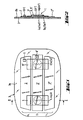
- the entire heating covering device according to the invention of which a first embodiment is shown in FIGS. 1 and 2 and a second in FIG. 3, is designated by the reference numbers 1 and 10, respectively.
- this heating device consists of three metal strips 2.2 ′ and 2 ′′, which are arranged at a distance from one another on the rear side 3a of the mirror 3.
- the device 1 further comprises two disk-shaped, electric heating elements 4, 4 ', the two main surfaces (large, flat surfaces) 4 a and 4 b of which are connected electrically and thermally conductively with different metal strips, so each heating element 4, 4' is over its main surfaces 4 a and 4 a ', which is the rear side 3 a of the mirror 3 are facing, electrically and thermally conductively connected to the central strip 2 '.
- the strips 2 and 2 " which are adjacent to the central strip 2 ', are electrically and thermally conductively connected to one another by means of metal bridges 5 and 5', and the main surfaces 4b and 4b ', which face away from the rear side 3a of the mirror 3, are also connected the undersides 5a and 5a 'of the metal bridges 5 and 5' electrically and thermally conductive connected.
- the metal strips 2, 2 'and 2 "serve not only for heat distribution but also as supply lines for electrical current.
- the heating elements 4 and 4 'can thus be connected in parallel, and electrical current then flows through them at the same time and in the same direction.
- the heating device 10 comprises four metal strips 20, 20 ', 20 “and 20” “and three heating elements 4, 4" and 4 “and three bridges 5.5” and 5 ".
- the bridges 5 and 5 connect the metal strips 20 and 20” and are in contact with the heating elements 4 and 4 "on their undersides, while the latter are in contact by means of their main surfaces facing the strip 20 '.
- the bridge 5 ' connects the metal strips 20' and 20 '"together, while electrical current from the terminal 6 of the strip 20'", which is connected to the minus pole of a car battery, through the heating wire of the heating element 4 'in the strip 20 "and flows back via connection 6 'of the latter to the positive pole of the battery.
Landscapes
- Engineering & Computer Science (AREA)
- Multimedia (AREA)
- Mechanical Engineering (AREA)
- Rear-View Mirror Devices That Are Mounted On The Exterior Of The Vehicle (AREA)
- Surface Heating Bodies (AREA)
- Resistance Heating (AREA)
- Optical Elements Other Than Lenses (AREA)
- Mirrors, Picture Frames, Photograph Stands, And Related Fastening Devices (AREA)
Applications Claiming Priority (2)
| Application Number | Priority Date | Filing Date | Title |
|---|---|---|---|
| DE8233516U | 1982-11-30 | ||
| DE19828233516U DE8233516U1 (de) | 1982-11-30 | 1982-11-30 | Elektrischer heizbelag fuer spiegel |
Publications (1)
| Publication Number | Publication Date |
|---|---|
| EP0110121A1 true EP0110121A1 (fr) | 1984-06-13 |
Family
ID=6746037
Family Applications (1)
| Application Number | Title | Priority Date | Filing Date |
|---|---|---|---|
| EP83110632A Withdrawn EP0110121A1 (fr) | 1982-11-30 | 1983-10-25 | Revêtement chauffant électrique pour miroir |
Country Status (4)
| Country | Link |
|---|---|
| US (1) | US4527047A (fr) |
| EP (1) | EP0110121A1 (fr) |
| JP (1) | JPS59106338A (fr) |
| DE (1) | DE8233516U1 (fr) |
Cited By (4)
| Publication number | Priority date | Publication date | Assignee | Title |
|---|---|---|---|---|
| WO1988010056A1 (fr) * | 1987-05-25 | 1988-12-15 | Ruthenberg Gmbh Waermetechnik | Dispositif de chauffage de surfaces situees dans ou sur des vehicules a moteur, telles que surfaces de sieges, vitres, retroviseurs ou similaires |
| EP0408207A3 (en) * | 1989-07-13 | 1992-01-22 | Illinois Tool Works Inc. | Positive temperature coefficient heater |
| US6891136B2 (en) | 2002-06-18 | 2005-05-10 | Http-Hypothermia Therapy Ltd. | Electrical heating device |
| US7329843B2 (en) | 2002-06-18 | 2008-02-12 | Http-Hypothermia Therapy Ltd. | Electrical heating device particularly for heating a patient body |
Families Citing this family (9)
| Publication number | Priority date | Publication date | Assignee | Title |
|---|---|---|---|---|
| DE3439958A1 (de) * | 1984-11-02 | 1986-05-07 | Dr.Ing.H.C. F. Porsche Ag, 7000 Stuttgart | Antibeschlagvorrichtung fuer ein schauglas eines anzeigeinstruments |
| US5043558A (en) * | 1990-09-26 | 1991-08-27 | Weed Instrument Company, Inc. | Deicing apparatus and method utilizing heat distributing means contained within surface channels |
| US5446576A (en) * | 1990-11-26 | 1995-08-29 | Donnelly Corporation | Electrochromic mirror for vehicles with illumination and heating control |
| GB2268916B (en) * | 1992-07-25 | 1995-11-01 | Ford Motor Co | A rear-view mirror installation for motor vehicles |
| US5459533A (en) * | 1993-11-12 | 1995-10-17 | See Clear Eyewear Inc. | Defogging eye wear |
| US5945872A (en) * | 1997-11-06 | 1999-08-31 | Analog Devices, Inc. | Two-phase boosted CMOS switch drive technique and circuit |
| US6118326A (en) * | 1997-11-06 | 2000-09-12 | Analog Devices, Inc. | Two-phase bootstrapped CMOS switch drive technique and circuit |
| US7306283B2 (en) | 2002-11-21 | 2007-12-11 | W.E.T. Automotive Systems Ag | Heater for an automotive vehicle and method of forming same |
| WO2006131785A2 (fr) * | 2004-03-22 | 2006-12-14 | W.E.T. Automotive Systems Ag | Appareil chauffant pour vehicule automobile et procede d'elaboration |
Citations (5)
| Publication number | Priority date | Publication date | Assignee | Title |
|---|---|---|---|---|
| US3720807A (en) * | 1972-05-01 | 1973-03-13 | Texas Instruments Inc | Food warming apparatus |
| US4237366A (en) * | 1979-03-19 | 1980-12-02 | Texas Instruments Incorporated | Heated automobile mirror |
| GB2054329A (en) * | 1979-07-11 | 1981-02-11 | Nkf Groep Bv | Heatable mirror |
| DE3042419A1 (de) * | 1980-11-11 | 1982-08-05 | Fritz Eichenauer GmbH & Co KG, 6744 Kandel | Vorrichtung zum beheizen von glatten flaechen, wie kraftfahrzeugspiegeln |
| EP0073521A1 (fr) * | 1981-09-02 | 1983-03-09 | Kabelwerke Reinshagen GmbH | Chauffage électrique pour un miroir d'une voiture automobile |
Family Cites Families (8)
| Publication number | Priority date | Publication date | Assignee | Title |
|---|---|---|---|---|
| US3307167A (en) * | 1963-12-06 | 1967-02-28 | Motorola Inc | Electrical control circuit including indirectly heated theremistor providing abrupt change in resistance with temperature |
| BE795169A (fr) * | 1972-02-09 | 1973-08-08 | Du Pont | Procede d'oxydation des chlorures de fer |
| US3996447A (en) * | 1974-11-29 | 1976-12-07 | Texas Instruments Incorporated | PTC resistance heater |
| DE2919968C3 (de) * | 1979-05-17 | 1984-09-13 | Hohe Kg, 6981 Collenberg | Elektrisch beheizbares Spiegelglas für Kraftfahrzeugaußenspiegel |
| DE8034131U1 (de) * | 1980-12-22 | 1981-05-27 | Kabelwerke Reinshagen Gmbh, 5600 Wuppertal | Elektrische heizvorrichtung |
| DE3048452C2 (de) * | 1980-12-22 | 1983-08-25 | Kabelwerke Reinshagen Gmbh, 5600 Wuppertal | Elektrische Heizvorrichtung |
| DE8125567U1 (de) * | 1981-09-02 | 1982-02-11 | Kabelwerke Reinshagen Gmbh, 5600 Wuppertal | Elektrisch beheizbare blechplatte, insbesondere fuer kraftfahrzeugspiegel |
| DE8214252U1 (de) * | 1982-05-15 | 1982-09-23 | Kabelwerke Reinshagen Gmbh, 5600 Wuppertal | Elektrisch beheizbare blechplatte, insbesondere fuer kraftfahrzeugspiegel |
-
1982
- 1982-11-30 DE DE19828233516U patent/DE8233516U1/de not_active Expired
-
1983
- 1983-10-20 US US06/543,788 patent/US4527047A/en not_active Expired - Fee Related
- 1983-10-25 EP EP83110632A patent/EP0110121A1/fr not_active Withdrawn
- 1983-11-14 JP JP58212614A patent/JPS59106338A/ja active Pending
Patent Citations (5)
| Publication number | Priority date | Publication date | Assignee | Title |
|---|---|---|---|---|
| US3720807A (en) * | 1972-05-01 | 1973-03-13 | Texas Instruments Inc | Food warming apparatus |
| US4237366A (en) * | 1979-03-19 | 1980-12-02 | Texas Instruments Incorporated | Heated automobile mirror |
| GB2054329A (en) * | 1979-07-11 | 1981-02-11 | Nkf Groep Bv | Heatable mirror |
| DE3042419A1 (de) * | 1980-11-11 | 1982-08-05 | Fritz Eichenauer GmbH & Co KG, 6744 Kandel | Vorrichtung zum beheizen von glatten flaechen, wie kraftfahrzeugspiegeln |
| EP0073521A1 (fr) * | 1981-09-02 | 1983-03-09 | Kabelwerke Reinshagen GmbH | Chauffage électrique pour un miroir d'une voiture automobile |
Cited By (4)
| Publication number | Priority date | Publication date | Assignee | Title |
|---|---|---|---|---|
| WO1988010056A1 (fr) * | 1987-05-25 | 1988-12-15 | Ruthenberg Gmbh Waermetechnik | Dispositif de chauffage de surfaces situees dans ou sur des vehicules a moteur, telles que surfaces de sieges, vitres, retroviseurs ou similaires |
| EP0408207A3 (en) * | 1989-07-13 | 1992-01-22 | Illinois Tool Works Inc. | Positive temperature coefficient heater |
| US6891136B2 (en) | 2002-06-18 | 2005-05-10 | Http-Hypothermia Therapy Ltd. | Electrical heating device |
| US7329843B2 (en) | 2002-06-18 | 2008-02-12 | Http-Hypothermia Therapy Ltd. | Electrical heating device particularly for heating a patient body |
Also Published As
| Publication number | Publication date |
|---|---|
| DE8233516U1 (de) | 1983-03-24 |
| US4527047A (en) | 1985-07-02 |
| JPS59106338A (ja) | 1984-06-20 |
Similar Documents
| Publication | Publication Date | Title |
|---|---|---|
| DE2739021C2 (fr) | ||
| DE3311803C2 (fr) | ||
| DE3644514C2 (fr) | ||
| DE4310288A1 (de) | Metall-Widerstand | |
| DE2815003A1 (de) | Verfahren zum einstellen des widerstandes eines thermistors | |
| EP0110121A1 (fr) | Revêtement chauffant électrique pour miroir | |
| DE1552962B2 (de) | Verfahren und vorrichtung zur aufbringung einer vielzahl von teilen eines heisschmelzbaren materials auf einen oder mehre re gegenstaende | |
| DE19822511B4 (de) | Auf einer Oberfläche befestigbare elektronische Bauelemente | |
| DE2065785B2 (de) | Elektrischer Schalter | |
| DE69104333T2 (de) | Beheizbare Verbundglasscheibe mit einem Kabelanschlussstück. | |
| DE2517087B2 (de) | Schaltungsanordnung zur elektrischen Beheizung und Regelung der Temperatur von beheizbaren Kraftfahrzeugscheiben | |
| DE2515044B2 (de) | Vorrichtung zur elektrischen verbindung einer vielzahl von mit abstand voneinander angeordneten elektrischen leitern | |
| DE3905190C1 (en) | Sensor device | |
| EP0076292A1 (fr) | Contact electrique, notamment pour circuits imprimes de petits appareils electriques. | |
| DE3711666A1 (de) | Temperaturschalter | |
| DE3543673A1 (de) | Einrichtung zum heizen | |
| DE2619242A1 (de) | Heizvorrichtung mit einem halbleiter-heizelement mit positivem temperaturkoeffizienten | |
| EP0370224A2 (fr) | Tapis contacteur pour sièges de véhicules | |
| DE2103057C2 (de) | Verfahren zur Befestigung von Elektrodenelementen an Anschlußstiften einer Gasentladungsanzeigevorrichtung | |
| DE2460698A1 (de) | Heizelement-metall-verbundglied | |
| DE3539318C2 (fr) | ||
| DE19623857C2 (de) | Elektrischer Widerstand | |
| DE69704025T2 (de) | Verfahren zur herstellung eines elektromechanischen relais | |
| DE2245376C3 (de) | Schalter, insbesondere Sitzschalter | |
| DE2253428A1 (de) | Trimmerpotentiometer, grundbauteile sowie verfahren zu seiner herstellung |
Legal Events
| Date | Code | Title | Description |
|---|---|---|---|
| PUAI | Public reference made under article 153(3) epc to a published international application that has entered the european phase |
Free format text: ORIGINAL CODE: 0009012 |
|
| AK | Designated contracting states |
Designated state(s): DE FR GB IT SE |
|
| ITCL | It: translation for ep claims filed |
Representative=s name: RICCARDI SERGIO & CO. |
|
| EL | Fr: translation of claims filed | ||
| 17P | Request for examination filed |
Effective date: 19840810 |
|
| STAA | Information on the status of an ep patent application or granted ep patent |
Free format text: STATUS: THE APPLICATION HAS BEEN WITHDRAWN |
|
| 18W | Application withdrawn |
Withdrawal date: 19860301 |
|
| RIN1 | Information on inventor provided before grant (corrected) |
Inventor name: SEITZ, RUDOLF, DIPL.-ING. |