EP0110212A2 - Assemblage à glisseur à coussin d'air pour tête magnétique - Google Patents
Assemblage à glisseur à coussin d'air pour tête magnétique Download PDFInfo
- Publication number
- EP0110212A2 EP0110212A2 EP83111225A EP83111225A EP0110212A2 EP 0110212 A2 EP0110212 A2 EP 0110212A2 EP 83111225 A EP83111225 A EP 83111225A EP 83111225 A EP83111225 A EP 83111225A EP 0110212 A2 EP0110212 A2 EP 0110212A2
- Authority
- EP
- European Patent Office
- Prior art keywords
- rail
- support
- slider assembly
- air bearing
- middle rail
- Prior art date
- Legal status (The legal status is an assumption and is not a legal conclusion. Google has not performed a legal analysis and makes no representation as to the accuracy of the status listed.)
- Withdrawn
Links
- 239000011521 glass Substances 0.000 claims description 6
- 238000004804 winding Methods 0.000 claims description 3
- 229910000859 α-Fe Inorganic materials 0.000 abstract description 6
- 230000001846 repelling effect Effects 0.000 abstract 1
- 230000000087 stabilizing effect Effects 0.000 abstract 1
- 239000013589 supplement Substances 0.000 abstract 1
- 238000000034 method Methods 0.000 description 6
- 238000005530 etching Methods 0.000 description 5
- 239000000463 material Substances 0.000 description 5
- 239000002184 metal Substances 0.000 description 5
- 229910052751 metal Inorganic materials 0.000 description 5
- 229920002120 photoresistant polymer Polymers 0.000 description 4
- 239000011248 coating agent Substances 0.000 description 3
- 238000000576 coating method Methods 0.000 description 3
- PXHVJJICTQNCMI-UHFFFAOYSA-N Nickel Chemical compound [Ni] PXHVJJICTQNCMI-UHFFFAOYSA-N 0.000 description 2
- 230000000712 assembly Effects 0.000 description 2
- 238000000429 assembly Methods 0.000 description 2
- 239000000725 suspension Substances 0.000 description 2
- 230000009471 action Effects 0.000 description 1
- 238000013459 approach Methods 0.000 description 1
- 230000008859 change Effects 0.000 description 1
- 238000004519 manufacturing process Methods 0.000 description 1
- 230000000873 masking effect Effects 0.000 description 1
- 230000007246 mechanism Effects 0.000 description 1
- 229910052759 nickel Inorganic materials 0.000 description 1
- 239000002245 particle Substances 0.000 description 1
- 238000001020 plasma etching Methods 0.000 description 1
- 230000008569 process Effects 0.000 description 1
- 230000009467 reduction Effects 0.000 description 1
- 230000000717 retained effect Effects 0.000 description 1
- 230000035945 sensitivity Effects 0.000 description 1
- 238000000926 separation method Methods 0.000 description 1
Images


Classifications
-
- G—PHYSICS
- G11—INFORMATION STORAGE
- G11B—INFORMATION STORAGE BASED ON RELATIVE MOVEMENT BETWEEN RECORD CARRIER AND TRANSDUCER
- G11B5/00—Recording by magnetisation or demagnetisation of a record carrier; Reproducing by magnetic means; Record carriers therefor
- G11B5/48—Disposition or mounting of heads or head supports relative to record carriers ; arrangements of heads, e.g. for scanning the record carrier to increase the relative speed
- G11B5/58—Disposition or mounting of heads or head supports relative to record carriers ; arrangements of heads, e.g. for scanning the record carrier to increase the relative speed with provision for moving the head for the purpose of maintaining alignment of the head relative to the record carrier during transducing operation, e.g. to compensate for surface irregularities of the latter or for track following
- G11B5/60—Fluid-dynamic spacing of heads from record-carriers
- G11B5/6005—Specially adapted for spacing from a rotating disc using a fluid cushion
-
- G—PHYSICS
- G11—INFORMATION STORAGE
- G11B—INFORMATION STORAGE BASED ON RELATIVE MOVEMENT BETWEEN RECORD CARRIER AND TRANSDUCER
- G11B5/00—Recording by magnetisation or demagnetisation of a record carrier; Reproducing by magnetic means; Record carriers therefor
- G11B5/10—Structure or manufacture of housings or shields for heads
- G11B5/105—Mounting of head within housing or assembling of head and housing
-
- G—PHYSICS
- G11—INFORMATION STORAGE
- G11B—INFORMATION STORAGE BASED ON RELATIVE MOVEMENT BETWEEN RECORD CARRIER AND TRANSDUCER
- G11B5/00—Recording by magnetisation or demagnetisation of a record carrier; Reproducing by magnetic means; Record carriers therefor
- G11B5/127—Structure or manufacture of heads, e.g. inductive
- G11B5/187—Structure or manufacture of the surface of the head in physical contact with, or immediately adjacent to the recording medium; Pole pieces; Gap features
- G11B5/1871—Shaping or contouring of the transducing or guiding surface
-
- G—PHYSICS
- G11—INFORMATION STORAGE
- G11B—INFORMATION STORAGE BASED ON RELATIVE MOVEMENT BETWEEN RECORD CARRIER AND TRANSDUCER
- G11B5/00—Recording by magnetisation or demagnetisation of a record carrier; Reproducing by magnetic means; Record carriers therefor
- G11B5/48—Disposition or mounting of heads or head supports relative to record carriers ; arrangements of heads, e.g. for scanning the record carrier to increase the relative speed
- G11B5/58—Disposition or mounting of heads or head supports relative to record carriers ; arrangements of heads, e.g. for scanning the record carrier to increase the relative speed with provision for moving the head for the purpose of maintaining alignment of the head relative to the record carrier during transducing operation, e.g. to compensate for surface irregularities of the latter or for track following
- G11B5/60—Fluid-dynamic spacing of heads from record-carriers
- G11B5/6005—Specially adapted for spacing from a rotating disc using a fluid cushion
- G11B5/6011—Control of flying height
- G11B5/6064—Control of flying height using air pressure
-
- G—PHYSICS
- G11—INFORMATION STORAGE
- G11B—INFORMATION STORAGE BASED ON RELATIVE MOVEMENT BETWEEN RECORD CARRIER AND TRANSDUCER
- G11B5/00—Recording by magnetisation or demagnetisation of a record carrier; Reproducing by magnetic means; Record carriers therefor
- G11B5/48—Disposition or mounting of heads or head supports relative to record carriers ; arrangements of heads, e.g. for scanning the record carrier to increase the relative speed
- G11B5/58—Disposition or mounting of heads or head supports relative to record carriers ; arrangements of heads, e.g. for scanning the record carrier to increase the relative speed with provision for moving the head for the purpose of maintaining alignment of the head relative to the record carrier during transducing operation, e.g. to compensate for surface irregularities of the latter or for track following
- G11B5/60—Fluid-dynamic spacing of heads from record-carriers
- G11B5/6005—Specially adapted for spacing from a rotating disc using a fluid cushion
- G11B5/6082—Design of the air bearing surface
Definitions
- This invention is directed to slider-transducer assemblies for magnetic recording and more particularly to ferrite slider assemblies where the head and transducer gap are formed simultaneously with the air bearing surfaces and the subambient pressure surfaces of the slider.
- US-A-3,823,416 describes a magnetic head slider assembly formed with parallel rails for generating an air bearing to maintain the head gap at a substantially constant distance from the recording surface.
- US-A-3,855,625 describes a magnetic head slider assembly formed with taper flat or step flat outer rails to provide a positive pressure region and with a recessed portion delineated by an inverse step cross rail between the outer rails and disposed toward the leading edge of the slider element to provide a negative pressure region.
- the configuration has closed sides and provides an air bearing at the slider surface facing a moving magnetic recording medium.
- the slider of the invention is retained during operation in the proper attitude of flight relative to the disk partly by the subambient pressure at the slider surface and partly by the load beam.
- This semi self-loading ability removes the need for a head loading and unloading mechanism and thereby avoids the problems associated with the loading and unloading functions.
- the same etching process that defines the air bearing surface and creates the etched areas that generate the subambient pressure also simultaneously defines the read-write head element.
- the etching technique provide the proper depth to the subambient pressure area, but also the exacting definition of the width of the transducer gap.
- the semi self-loading slider of the invention reaches the burnish level at one third the disk speed. This reduces to one third the contact duration and reduces to one ninth the contact distance or number of revolutions to make an important contribution to wear reduction during start-stop operations.
- the semi self-loading slider also has a very small change in fly height over a wide range of rotational velocity which offers the potential of increasing the recording density at the outer zones of the disk where greater tangential velocity occurs.
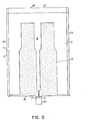
- the slider has a ferrite body 10 that presents an air bearing surface 11.
- the air bearing surface 11 includes a pair of side rails 13, 14; a cross rail 15 and a middle rail 16 all of which are coplanar.
- Adjoining the leading edge 28 of the slider is a tapered leading surface portion 18. This extends from the air surface defined by the common plane defined by the rail surfaces 13, 14, 15, 16 and is inclined thereto by an angle of as little as 0,4°.
- the leading edge surface 18 is inclined to the plane of the air bearing surface 11 by an angle of approximately 0,6°.
- the slider surfaces 21, 22 between the side rails 13, 14 and middle rail 16 and the marginal surfaces 24 that define the outer and trailing edges of the side rails 13, 14 are etched to a depth not exceeding 25,4 ⁇ m and are preferably within the range of 11 to 171am in depth.
- positive and negative or subambient pressure zones are formed to provide opposing load forces on the assembly that in cooperation with the load component supplied by the load arm are virtually counter balanced.
- the positive pressure occurs along the cross rail 15, the side rails 13, 14 and to a lesser extent because of its narrower dimension, the middle rail 16.
- the negative or subambient pressure zone occurs in the etched, recessed regions 21 and 22 intermediate the side rails and the middle rail. The highest negative pressure occurs adjacent the cross rail 15 and slowly diminishes toward the trailing edge 38 of the slider where it rapidly approaches atmospheric.
- the ferrite slider body also has a transverse suspension groove 25 and a transverse groove 27 formed therein.
- a straight ferrite core piece 29 is secured to slider body 10 by glass 31 adjoining the front gap portion and by glass 32 at the interface with the slider body surface.
- the transducer coil is wound around the core piece 29 and extends into the window groove which is provided to accomodate the coil and provide access space for the winding operation during manufacture.
- the read/write gap 35 is formed in the trailing portions of the air bearing surface middle rail portion 37 between the rail portions formed by body 10 and core 29. Although the gap extends across the width of core piece 29, the effective working gap is limited to the width of the middle rail portion 37 at the gap location 35 at the operating frequencies of the transducer.
- the slider assembly is formed with the support or body 10 having a continuous super finished surface in the planes where the air bearing rail surfaces are formed and the tapered surface 18.
- a mounting groove 25 is formed in the body 10 and a window groove 27 to accomodate the transducer winding.
- the window groove may be formed as shown with a recess 27 in the body 10 or may take the form of a C-shaped core piece bonded to a body having a planar rear wall.
- the core piece 29 is glass bonded by glassing material 31 which both causes adhesion and forms the transducer gap 35 at the front gap and by glassing material 32 at the back gap location.
- the upper surface of pole piece 29 is coplanar with the body 10 superfinished surface.
- the definition of the air bearing surface rails is determined and the subambient pressure region generated.
- This procedure may be conducted in accordance with reactive ion etching and masking techniques shown and described in US-A-4,375,390.
- a thin conductive metal coating is applied to the superfinished surface.
- the taper surface 18 and air bearing rail surfaces, including the trailing narrow middle rail portion that defines the transducer gap are defined and exposed and the photo resist developed to expose the metal film in those locations where the super finished surface is to be preserved for the taper and air bearing surfaces.
- the exposed metal film is then plated with nickel to form a mask.
- the surface is reactive ion etched to form the subambient pressure areas 21, 22 and the margins 24 which adjoin and define the air bearing rail surfaces.
- the same etching operation by defining the rearward narrowest portion of the middle rail 16, establishes the transducer head width.
- the etch depth is typically in the range of 15 to 20 pm.
- the etching may selectively remove the glass material at each lateral side of the transducer gap 35 somewhat more deeply due to the greater etch rate of glass compared to the ferrite of the body 10 and core 29. This further assists in isolating the transducer action of the head to the desired gap or recording track width as desired.
- the semi self-loading slider maintains a more uniform height above the surface than the common taper-flat design. With less variation there is less concern about height fluctuation and the possibility of operating below the burnish height of the media surface.
- the air bearing pressure urges the transducer-slider away from the confronting surface while the force urging the slider toward the surface is composed of the negative pressure imparted by the etched surface region intermediate the rails and the load applied by the load arm.
- the fact that the air bearing pressure reduces rapidly as separation between the media and air bearing surface increases causes the slider-transducer fly height to be self-regulating as established by the air bearing/etched surface design configuration and the constant rotational speed at which the disk is driven.
Landscapes
- Engineering & Computer Science (AREA)
- Manufacturing & Machinery (AREA)
- Adjustment Of The Magnetic Head Position Track Following On Tapes (AREA)
Applications Claiming Priority (2)
| Application Number | Priority Date | Filing Date | Title |
|---|---|---|---|
| US06/444,767 US4555739A (en) | 1982-11-26 | 1982-11-26 | Semi self-loading ferrite head |
| US444767 | 1982-11-26 |
Publications (2)
| Publication Number | Publication Date |
|---|---|
| EP0110212A2 true EP0110212A2 (fr) | 1984-06-13 |
| EP0110212A3 EP0110212A3 (fr) | 1985-11-13 |
Family
ID=23766272
Family Applications (1)
| Application Number | Title | Priority Date | Filing Date |
|---|---|---|---|
| EP83111225A Withdrawn EP0110212A3 (fr) | 1982-11-26 | 1983-11-10 | Assemblage à glisseur à coussin d'air pour tête magnétique |
Country Status (3)
| Country | Link |
|---|---|
| US (1) | US4555739A (fr) |
| EP (1) | EP0110212A3 (fr) |
| JP (1) | JPS59132416A (fr) |
Cited By (7)
| Publication number | Priority date | Publication date | Assignee | Title |
|---|---|---|---|---|
| EP0237752A1 (fr) * | 1986-03-20 | 1987-09-23 | International Business Machines Corporation | Patin flottant sur coussin d'air |
| EP0308527A1 (fr) * | 1987-09-22 | 1989-03-29 | Ibm Deutschland Gmbh | Forme du rail d'un patin à coussin d'air et son procédé mécanique de réalisation |
| EP0576723A1 (fr) * | 1992-05-29 | 1994-01-05 | TDK Corporation | Tête magnétique et sa méthode de fabrication |
| EP0614175A1 (fr) * | 1993-03-01 | 1994-09-07 | Read-Rite Corporation | Patin flottant sur coussin d'air pour tête magnétique |
| EP0647936A3 (fr) * | 1993-10-07 | 1995-11-15 | Read Rite Corp | Glisseurs améliorés, à palier d'air, pour tête magnétique. |
| US5704112A (en) * | 1992-05-29 | 1998-01-06 | Tdk Corporation | Method of manufacturing a magnetic head |
| US6603638B2 (en) | 2000-07-04 | 2003-08-05 | Sony Corporation | Floating-type head slider and recording/reproducing apparatus employing the same |
Families Citing this family (50)
| Publication number | Priority date | Publication date | Assignee | Title |
|---|---|---|---|---|
| US4823216A (en) * | 1987-10-23 | 1989-04-18 | Applied Magnetics Corporation | Microminimonolithic magnetic head slider |
| US4972279A (en) * | 1981-10-23 | 1990-11-20 | Applied Magnetics Corporation | Microminimonolithic magnetic head slider |
| JPS60131613A (ja) * | 1983-12-20 | 1985-07-13 | Alps Electric Co Ltd | 浮動磁気ヘツド |
| DE3630841A1 (de) * | 1985-09-13 | 1987-03-26 | Hitachi Metals Ltd | Fliegender magnetkopf |
| JPS62200517A (ja) * | 1986-02-27 | 1987-09-04 | Alps Electric Co Ltd | 垂直磁気記録用磁気ヘツドおよびその製造方法 |
| US4802042A (en) * | 1987-02-05 | 1989-01-31 | Magnetic Peripherals Inc. | Side-vented magnetic head air bearing slider |
| US5081553A (en) * | 1988-03-31 | 1992-01-14 | Applied Magnetics Corporation | Combination of elongated load arm and microminimonolithic head slider |
| US5124865A (en) * | 1988-03-31 | 1992-06-23 | Applied Magnetics Corporation | Microminimonolithic magnetic head slider having vertically extending slots to reduce flux leakage losses |
| US5012572A (en) * | 1988-03-31 | 1991-05-07 | Ngk Insulators, Ltd. | Method for producing a head core slider |
| US4894740A (en) * | 1988-09-28 | 1990-01-16 | International Business Machines Corporation | Magnetic head air bearing slider |
| US5072322A (en) * | 1988-10-17 | 1991-12-10 | National Micronetics, Inc. | Monolithic ferrite recording head with glass-protected, self-aligned, machined track |
| US5097370A (en) * | 1989-03-17 | 1992-03-17 | Digital Equipment Corporation | Subambient pressure air bearing slider for disk drive |
| JP2940023B2 (ja) * | 1989-10-30 | 1999-08-25 | ソニー株式会社 | 遊離砥粒を用いた加工方法 |
| US5021906A (en) * | 1989-10-31 | 1991-06-04 | International Business Machines Corporation | Programmable air bearing slider including magnetic read/write element |
| US5162073A (en) * | 1990-02-15 | 1992-11-10 | Applied Magnetics Corporation | Textured air bearing surface |
| US5200868A (en) * | 1990-05-25 | 1993-04-06 | Seagate Technology, Inc. | Negative pressure air bearing slider having an air bearing surface trailing a negative pressure cavity |
| US5196973A (en) * | 1990-05-25 | 1993-03-23 | Seagate Technology, Inc. | Negative pressure air bearing slider having isolation channels which terminate prior to trailing edge |
| US5218495A (en) * | 1990-05-25 | 1993-06-08 | Seagate Technology, Inc. | Negative pressure air bearing slider with spoiler channels |
| US5128822A (en) * | 1990-05-25 | 1992-07-07 | Seagate Technology, Inc. | Configuration for negative pressure air bearing sliders |
| US5343343A (en) * | 1990-05-25 | 1994-08-30 | Seagate Technology, Inc. | Air bearing slider with relieved rail ends |
| US5218494A (en) * | 1990-05-25 | 1993-06-08 | Seagate Technology, Inc. | Negative pressure air bearing slider having isolation channels with edge step |
| US5274518A (en) * | 1990-05-25 | 1993-12-28 | Seagate Technology, Inc. | Negative pressure air bearing slider having converging isolation channels |
| US5210666A (en) * | 1990-05-25 | 1993-05-11 | Seagate Technology, Inc. | Self-loading air bearing slider with a relieved leading edge |
| US5156704A (en) * | 1990-06-01 | 1992-10-20 | Computer And Communications Technology Corp. | Method for fabricating magnetic head air bearing sliders |
| US5086360A (en) * | 1990-09-06 | 1992-02-04 | Applied Magnetics Corporation | Constant flying height slider |
| US5267109A (en) * | 1991-06-14 | 1993-11-30 | Seagate Technology, Inc. | Air bearing slider with relieved trailing edge |
| US5473485A (en) * | 1992-03-06 | 1995-12-05 | Read-Rite Corporation | Tripad air bearing magnetic head slider |
| US5438467A (en) * | 1992-10-28 | 1995-08-01 | International Business Machines Corporation | Negative pressure air bearing design |
| US5654850A (en) * | 1993-05-18 | 1997-08-05 | Applied Magnetics Corp. | Carbon overcoat with electrically conductive adhesive layer for magnetic head sliders |
| US5336550A (en) * | 1993-05-18 | 1994-08-09 | Applied Magnetics Corporation | Carbon overcoat for magnetic head sliders |
| US5636086A (en) * | 1993-05-28 | 1997-06-03 | International Business Machines Corporation | Roll insensitive air bearing slider |
| US5452166A (en) * | 1993-10-01 | 1995-09-19 | Applied Magnetics Corporation | Thin film magnetic recording head for minimizing undershoots and a method for manufacturing the same |
| US5488524A (en) * | 1993-12-21 | 1996-01-30 | International Business Machines Corporation | Self adaptive head for semi-contact recording |
| US6292332B1 (en) | 1996-01-16 | 2001-09-18 | Seagate Technology Llc | Compliant air bearing slider with wide midpoint rails for reliable proximity recording |
| US5677812A (en) * | 1996-01-26 | 1997-10-14 | Samsung Electronics, North America | Air bearing slider with variable sub-ambient pressure control |
| US5831791A (en) * | 1996-03-27 | 1998-11-03 | Headway Technologies, Inc. | Negative Pressure air bearing slider having transition region between positive and negative pressure regions |
| US6034842A (en) * | 1996-08-30 | 2000-03-07 | Sae Magnetics (H.K.) Ltd. | Subambient pressure slider for constant flying height |
| US5986850A (en) * | 1997-06-16 | 1999-11-16 | Seagate Technology, Inc. | Positive pressure optical slider having wide center rail |
| WO1999005679A1 (fr) | 1997-07-23 | 1999-02-04 | Seagate Technology, Inc. | Curseur optique a pression positive avec plages de connexion laterales a extremite arriere |
| US6704161B1 (en) | 1998-11-06 | 2004-03-09 | Samsung Electronics Co. Ltd. | Shock protection skin bumper for a hard disk drive |
| US6417986B1 (en) | 1998-11-16 | 2002-07-09 | Samsung Electronics Co., Ltd. | Impact guard for limiting hard disk movement |
| US6549372B1 (en) | 1998-12-15 | 2003-04-15 | Samsung Electronics Co., Ltd | Device for limiting head movement within a hard disk drive |
| US6417994B1 (en) | 1999-04-22 | 2002-07-09 | Samsung Electronics, Co., Ltd. | Swage plate with protruded walls to increase retention torque in hard disk applications |
| US6501614B1 (en) | 1999-08-19 | 2002-12-31 | Samsung Electronics Co., Ltd. | Acoustic insulator for controlling noise generated in a mass storage device |
| US6744597B2 (en) | 1999-10-29 | 2004-06-01 | Samsung Electronics Co., Ltd. | Dynamic absorber for an actuator arm in a disk drive |
| US6947252B2 (en) | 2000-05-10 | 2005-09-20 | Samsung Electronics Co., Ltd. | Wave stringer for controlling acoustic noise and shock vibration in a storage device |
| US6446517B1 (en) | 2000-11-20 | 2002-09-10 | Samsung Electronics Company | Controlled particle deposition in drives and on media for thermal asperity studies |
| US6590738B2 (en) | 2001-03-01 | 2003-07-08 | Samsung Electronics Co., Ltd. | Particle removal device in a hard disk drive |
| US6762908B2 (en) | 2001-06-18 | 2004-07-13 | Samsung Electronics Co., Ltd. | Air razor and disk limiter for a hard disk drive |
| JP5597001B2 (ja) * | 2010-03-17 | 2014-10-01 | セイコーインスツル株式会社 | 近接場光アシスト磁気記録ヘッド、ヘッドジンバルアセンブリ及びそれを備えた情報記録再生装置 |
Family Cites Families (5)
| Publication number | Priority date | Publication date | Assignee | Title |
|---|---|---|---|---|
| US3823416A (en) * | 1973-03-01 | 1974-07-09 | Ibm | Flying magnetic transducer assembly having three rails |
| US3855625A (en) * | 1973-12-19 | 1974-12-17 | Ibm | Magnetic head slider assembly |
| FR2408897A1 (fr) * | 1977-11-15 | 1979-06-08 | Cii Honeywell Bull | Procede du temps de decollage d'une plate-forme comportant au moins un transducteur de lecture/ecriture d'un support d'information, plate-forme resultant de l'execution du procede, et procede de fabrication d'une telle plate-forme |
| JPS55105857A (en) * | 1979-02-02 | 1980-08-13 | Nippon Telegr & Teleph Corp <Ntt> | Floating head slider |
| US4218715A (en) * | 1979-03-12 | 1980-08-19 | International Business Machines Corporation | Magnetic head slider assembly |
-
1982
- 1982-11-26 US US06/444,767 patent/US4555739A/en not_active Expired - Fee Related
-
1983
- 1983-11-10 EP EP83111225A patent/EP0110212A3/fr not_active Withdrawn
- 1983-11-24 JP JP58219631A patent/JPS59132416A/ja active Pending
Cited By (9)
| Publication number | Priority date | Publication date | Assignee | Title |
|---|---|---|---|---|
| EP0237752A1 (fr) * | 1986-03-20 | 1987-09-23 | International Business Machines Corporation | Patin flottant sur coussin d'air |
| EP0308527A1 (fr) * | 1987-09-22 | 1989-03-29 | Ibm Deutschland Gmbh | Forme du rail d'un patin à coussin d'air et son procédé mécanique de réalisation |
| EP0576723A1 (fr) * | 1992-05-29 | 1994-01-05 | TDK Corporation | Tête magnétique et sa méthode de fabrication |
| US5704112A (en) * | 1992-05-29 | 1998-01-06 | Tdk Corporation | Method of manufacturing a magnetic head |
| US6125004A (en) * | 1992-05-29 | 2000-09-26 | Tdk Corporation | Magnetic head and method of manufacturing a magnetic head |
| EP0614175A1 (fr) * | 1993-03-01 | 1994-09-07 | Read-Rite Corporation | Patin flottant sur coussin d'air pour tête magnétique |
| EP0647936A3 (fr) * | 1993-10-07 | 1995-11-15 | Read Rite Corp | Glisseurs améliorés, à palier d'air, pour tête magnétique. |
| US6603638B2 (en) | 2000-07-04 | 2003-08-05 | Sony Corporation | Floating-type head slider and recording/reproducing apparatus employing the same |
| SG102629A1 (en) * | 2000-07-04 | 2004-03-26 | Sony Corp | Floating-type head slider and recording/reproducing apparatus employing the same |
Also Published As
| Publication number | Publication date |
|---|---|
| JPS59132416A (ja) | 1984-07-30 |
| US4555739A (en) | 1985-11-26 |
| EP0110212A3 (fr) | 1985-11-13 |
Similar Documents
| Publication | Publication Date | Title |
|---|---|---|
| US4555739A (en) | Semi self-loading ferrite head | |
| EP0155756B1 (fr) | Assemblage à patin pour tête d'enregistrement | |
| EP0107411B1 (fr) | Patin pour tête magnétique flottante | |
| US4734803A (en) | Magnetic head air bearing slider | |
| JP2585248B2 (ja) | 磁気ヘッドスライダ | |
| US5406432A (en) | Air bearing magnetic head sliders with separate center rail segments | |
| US5488524A (en) | Self adaptive head for semi-contact recording | |
| JP2779529B2 (ja) | 浮動ヘッドスライダ | |
| EP0847044A1 (fr) | Patin à coussin d'air insensible à l'altitude | |
| JPH11353774A (ja) | 磁気ヘッド | |
| JP2872384B2 (ja) | 磁気ヘツドスライダ及び磁気デイスク装置 | |
| JPS63298879A (ja) | 磁気ヘッドスライダ及びその製造方法 | |
| JP2001508579A (ja) | 後縁カットで終了するサイド・レールを有するスライダー | |
| JPH11353773A (ja) | 磁気ヘッド | |
| JPH01211234A (ja) | 浮動ヘッドスライダ | |
| EP0238727A1 (fr) | Glisseur pour tête magnétique et procédé conçu pour la fabrication d'un tel glisseur | |
| JP2986502B2 (ja) | 浮上式スライダ | |
| JPH08321026A (ja) | 浮上型磁気ヘッドとその製造方法 | |
| JPH0845047A (ja) | 磁気ヘッドスライダ組立体 | |
| JPH06111508A (ja) | 磁気ヘッド | |
| JPH03127317A (ja) | 浮上型磁気ヘッド | |
| JP2932865B2 (ja) | 磁気ヘッドの製造方法 | |
| JP2906653B2 (ja) | 浮上型磁気ヘッド装置 | |
| JPH03228274A (ja) | 磁気ヘツド及びその製造方法 | |
| JPH0668632A (ja) | 浮動ヘッドスライダ |
Legal Events
| Date | Code | Title | Description |
|---|---|---|---|
| PUAI | Public reference made under article 153(3) epc to a published international application that has entered the european phase |
Free format text: ORIGINAL CODE: 0009012 |
|
| AK | Designated contracting states |
Designated state(s): DE FR GB |
|
| 17P | Request for examination filed |
Effective date: 19840921 |
|
| PUAL | Search report despatched |
Free format text: ORIGINAL CODE: 0009013 |
|
| AK | Designated contracting states |
Designated state(s): DE FR GB |
|
| 17Q | First examination report despatched |
Effective date: 19870522 |
|
| STAA | Information on the status of an ep patent application or granted ep patent |
Free format text: STATUS: THE APPLICATION IS DEEMED TO BE WITHDRAWN |
|
| 18D | Application deemed to be withdrawn |
Effective date: 19871002 |
|
| RIN1 | Information on inventor provided before grant (corrected) |
Inventor name: LE VAN, DIEN Inventor name: WALLACE, JESSE TAYLOR |