EP0110254B1 - Procédé de fabrication de lames de ressorts en matériaux composites renforcés avec des fibres - Google Patents
Procédé de fabrication de lames de ressorts en matériaux composites renforcés avec des fibres Download PDFInfo
- Publication number
- EP0110254B1 EP0110254B1 EP83111502A EP83111502A EP0110254B1 EP 0110254 B1 EP0110254 B1 EP 0110254B1 EP 83111502 A EP83111502 A EP 83111502A EP 83111502 A EP83111502 A EP 83111502A EP 0110254 B1 EP0110254 B1 EP 0110254B1
- Authority
- EP
- European Patent Office
- Prior art keywords
- leaf springs
- thickness
- winding
- fibre
- production
- Prior art date
- Legal status (The legal status is an assumption and is not a legal conclusion. Google has not performed a legal analysis and makes no representation as to the accuracy of the status listed.)
- Expired
Links
- 238000004519 manufacturing process Methods 0.000 title claims description 9
- 239000002131 composite material Substances 0.000 title description 3
- 238000004804 winding Methods 0.000 claims description 24
- 239000000835 fiber Substances 0.000 claims description 12
- 238000000034 method Methods 0.000 claims description 10
- 239000004033 plastic Substances 0.000 claims description 10
- 229920003023 plastic Polymers 0.000 claims description 10
- 239000000463 material Substances 0.000 claims description 6
- 239000000155 melt Substances 0.000 claims description 3
- 239000007858 starting material Substances 0.000 claims 1
- 229920005989 resin Polymers 0.000 description 2
- 239000011347 resin Substances 0.000 description 2
- 229920001169 thermoplastic Polymers 0.000 description 2
- 239000004416 thermosoftening plastic Substances 0.000 description 2
- OKTJSMMVPCPJKN-UHFFFAOYSA-N Carbon Chemical compound [C] OKTJSMMVPCPJKN-UHFFFAOYSA-N 0.000 description 1
- 239000004743 Polypropylene Substances 0.000 description 1
- 239000004760 aramid Substances 0.000 description 1
- 229920003235 aromatic polyamide Polymers 0.000 description 1
- 229910052799 carbon Inorganic materials 0.000 description 1
- 239000003054 catalyst Substances 0.000 description 1
- 239000010432 diamond Substances 0.000 description 1
- 239000003822 epoxy resin Substances 0.000 description 1
- 230000002349 favourable effect Effects 0.000 description 1
- 239000011521 glass Substances 0.000 description 1
- LNEPOXFFQSENCJ-UHFFFAOYSA-N haloperidol Chemical compound C1CC(O)(C=2C=CC(Cl)=CC=2)CCN1CCCC(=O)C1=CC=C(F)C=C1 LNEPOXFFQSENCJ-UHFFFAOYSA-N 0.000 description 1
- 239000007788 liquid Substances 0.000 description 1
- 238000003801 milling Methods 0.000 description 1
- 229920000647 polyepoxide Polymers 0.000 description 1
- -1 polypropylene Polymers 0.000 description 1
- 229920001155 polypropylene Polymers 0.000 description 1
- 239000012783 reinforcing fiber Substances 0.000 description 1
- 238000007493 shaping process Methods 0.000 description 1
- 229920006305 unsaturated polyester Polymers 0.000 description 1
- 229920001567 vinyl ester resin Polymers 0.000 description 1
Images
Classifications
-
- B—PERFORMING OPERATIONS; TRANSPORTING
- B29—WORKING OF PLASTICS; WORKING OF SUBSTANCES IN A PLASTIC STATE IN GENERAL
- B29D—PRODUCING PARTICULAR ARTICLES FROM PLASTICS OR FROM SUBSTANCES IN A PLASTIC STATE
- B29D99/00—Subject matter not provided for in other groups of this subclass
- B29D99/0003—Producing profiled members, e.g. beams
- B29D99/0007—Producing profiled members, e.g. beams having a variable cross-section
-
- B—PERFORMING OPERATIONS; TRANSPORTING
- B29—WORKING OF PLASTICS; WORKING OF SUBSTANCES IN A PLASTIC STATE IN GENERAL
- B29C—SHAPING OR JOINING OF PLASTICS; SHAPING OF MATERIAL IN A PLASTIC STATE, NOT OTHERWISE PROVIDED FOR; AFTER-TREATMENT OF THE SHAPED PRODUCTS, e.g. REPAIRING
- B29C53/00—Shaping by bending, folding, twisting, straightening or flattening; Apparatus therefor
- B29C53/56—Winding and joining, e.g. winding spirally
- B29C53/564—Winding and joining, e.g. winding spirally for making non-tubular articles
-
- F—MECHANICAL ENGINEERING; LIGHTING; HEATING; WEAPONS; BLASTING
- F16—ENGINEERING ELEMENTS AND UNITS; GENERAL MEASURES FOR PRODUCING AND MAINTAINING EFFECTIVE FUNCTIONING OF MACHINES OR INSTALLATIONS; THERMAL INSULATION IN GENERAL
- F16F—SPRINGS; SHOCK-ABSORBERS; MEANS FOR DAMPING VIBRATION
- F16F1/00—Springs
- F16F1/36—Springs made of rubber or other material having high internal friction, e.g. thermoplastic elastomers
- F16F1/366—Springs made of rubber or other material having high internal friction, e.g. thermoplastic elastomers made of fibre-reinforced plastics, i.e. characterised by their special construction from such materials
- F16F1/368—Leaf springs
-
- B—PERFORMING OPERATIONS; TRANSPORTING
- B29—WORKING OF PLASTICS; WORKING OF SUBSTANCES IN A PLASTIC STATE IN GENERAL
- B29L—INDEXING SCHEME ASSOCIATED WITH SUBCLASS B29C, RELATING TO PARTICULAR ARTICLES
- B29L2031/00—Other particular articles
- B29L2031/774—Springs
Definitions
- the invention relates to a method for producing spring bars made of fiber composite materials which are variable in height to width ratio, preferably curved, using the winding method.
- the invention was based on the object of developing a method for the production of preferably curved spring bars from plastics reinforced with several layers of continuous fibers, which have a constant cross-sectional area over the length with a variable height-to-width ratio, according to the winding process.
- the starting point was the fact that spiral springs with a constant cross-sectional area over their length and a height-to-width ratio that varies according to the load profile are lighter in weight and have a more favorable material utilization than those with a constant rectangular cross-section.
- the winding core is provided with a plurality of rows of diamond-shaped elevations arranged next to one another in such a way that the fiber strands intersect at defined locations in the mold cavities formed by the elevations.
- the fiber strands are deposited according to a predetermined pattern at a defined angle to the axis of the winding core in such a way that the height-to-width ratio changes largely optimally in accordance with the mechanical load on the spiral spring.
- the number of rows can vary from 1 to 100, preferably between 1 and 10; the number of diamonds can be 2 to 20.
- the crossing angle of the rovings is preferably between 3 and 15, in particular about 6 °.
- the winding core generally has a circular cylindrical cross section with a radius which corresponds to the pre-curvature of the spring bars. However, it can also, preferably in the case of larger, slightly curved or straight spring bars, be designed in cross section as a polygon which is constructed from two or more shells.
- the winding core can be a lost or a reusable winding core which, for. B. consists of an excitingly easily editable material.
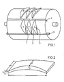
- FIG. 1 shows an example of a winding core.
- a blank is particularly a thick-walled extruded or wound tube made of a thermoplastic, such. B. polypropylene.
- the cavities 1 in the winding core are produced by milling or turning. They serve as a lateral limitation in the sense of shape nests.
- the winding core preferably has bores 2 in the middle of the mold cavities for receiving bolts or elongated inserts. They are used to create recesses in the spring bars for fastening purposes. Further bores 3 are located in two or more of the raised core parts of each row of mold cavities for fastening shell elements acting as patrices. These correspondingly curved shells have the length of the winding mandrel.
- the winding mandrel is expediently provided at one or more points with longitudinal grooves 4, which are filled with corresponding strips 5 made of the same or different material during the winding.
- the impregnated fibers are deposited in the intended number on the rotating winding mandrel by moving the thread guide eye back and forth several times.
- the male parts can then be placed and pressed on. After curing, these are removed and the strips are pulled out of the grooves. Then the laminate is cut lengthways on these strips so that the spring bars created can be easily removed from the mandrel.
- the reinforcing fibers can consist of glass, carbon or aromatic polyamides, they are available as continuous fiber rovings with 50 to 2400tex. You can also wrap different types of fibers in separate layers or as real hybrid scrims.
- thermoplastics can be used as impregnating resins. They are used in liquid form as a melt or solution of the plastics or their starting product. After the winding process, the plastic is solidified and, if necessary, cured, suitable catalysts being added to it, or elevated temperatures being used, depending on the type of plastic.
- the dimensions of the spring bars produced according to the invention can vary within wide limits: in the length I from 20 to 150 cm, in the width b from 2 to 20 cm, in the height h from 0.5 to 10 cm; they can have a radius of curvature of 20 cm to x.
- the ratio of the height h in the middle of the bars to the height h z at the end of the bars can be between 20: 1 and 1.1: 1, preferably between 4: 1 and 2: 1, (sketch see Fig. 2).
Landscapes
- Engineering & Computer Science (AREA)
- Mechanical Engineering (AREA)
- General Engineering & Computer Science (AREA)
- Moulding By Coating Moulds (AREA)
- Springs (AREA)
Claims (3)
Applications Claiming Priority (2)
| Application Number | Priority Date | Filing Date | Title |
|---|---|---|---|
| DE3243519 | 1982-11-25 | ||
| DE19823243519 DE3243519A1 (de) | 1982-11-25 | 1982-11-25 | Verfahren zur herstellung von federstaeben aus faserverbundwerkstoffen |
Publications (2)
| Publication Number | Publication Date |
|---|---|
| EP0110254A1 EP0110254A1 (fr) | 1984-06-13 |
| EP0110254B1 true EP0110254B1 (fr) | 1986-03-12 |
Family
ID=6178941
Family Applications (1)
| Application Number | Title | Priority Date | Filing Date |
|---|---|---|---|
| EP83111502A Expired EP0110254B1 (fr) | 1982-11-25 | 1983-11-17 | Procédé de fabrication de lames de ressorts en matériaux composites renforcés avec des fibres |
Country Status (2)
| Country | Link |
|---|---|
| EP (1) | EP0110254B1 (fr) |
| DE (2) | DE3243519A1 (fr) |
Families Citing this family (6)
| Publication number | Priority date | Publication date | Assignee | Title |
|---|---|---|---|---|
| DE3527964C1 (de) * | 1985-08-03 | 1987-04-16 | Boehler Ag | Verfahren und Vorrichtung zur Herstellung von langgestreckten Koerpern mit faserverstaerktem Kunststoff |
| FR2637217B1 (fr) * | 1988-10-04 | 1991-01-04 | Alsthom Gec | Procede de fabrication d'une lame de ressort en fibres impregnees de resine par enroulement filamentaire |
| FR2656826B1 (fr) * | 1990-01-10 | 1995-07-21 | Mediterranee Const Ind | Dispositif pour la fabrication de lames de ressort composites. |
| US5158631A (en) * | 1991-01-15 | 1992-10-27 | United Technologies Corporation | Method of manufacturing a dog-leg shaped ply of composite material and the tool used in carrying out the method |
| FR2710870B1 (fr) * | 1993-10-08 | 1995-12-08 | Inst Francais Du Petrole | Dispositif et méthode de fabrication en série de pièces en résine renforcée par des fibres. |
| FR2739802B1 (fr) * | 1995-10-12 | 1998-01-02 | Cpl Composites Des Pays De Loi | Pieces de forme a section constante, en materiau composite et leur dispositif de fabrication a partir d'enroulements en echeveaux de fibres continues impregnees de resine thermodurcissable |
Family Cites Families (5)
| Publication number | Priority date | Publication date | Assignee | Title |
|---|---|---|---|---|
| US3900357A (en) * | 1970-05-04 | 1975-08-19 | Edgewater Corp | Composite material springs and manufacture |
| GB2021731A (en) * | 1978-05-26 | 1979-12-05 | Gkn Group Services Ltd | Leaf springs of fibre-reinforced plastics |
| ZA821612B (en) * | 1981-03-21 | 1983-01-26 | Gkn Technology Ltd | Manufacture of springs of fibre reinforced composite material |
| BR8203375A (pt) * | 1981-06-15 | 1983-05-31 | Budd Co | Folha de mola para suspensao de estruturas recipocas e processo de sua fabricacao |
| DE3238099C2 (de) * | 1981-12-18 | 1983-11-17 | Messerschmitt-Bölkow-Blohm GmbH, 8000 München | Biegefeder aus faserverstärktem Kunststoff und Preßwerkzeug für deren Fertigung |
-
1982
- 1982-11-25 DE DE19823243519 patent/DE3243519A1/de not_active Withdrawn
-
1983
- 1983-11-17 EP EP83111502A patent/EP0110254B1/fr not_active Expired
- 1983-11-17 DE DE8383111502T patent/DE3362563D1/de not_active Expired
Also Published As
| Publication number | Publication date |
|---|---|
| DE3243519A1 (de) | 1984-05-30 |
| EP0110254A1 (fr) | 1984-06-13 |
| DE3362563D1 (en) | 1986-04-17 |
Similar Documents
| Publication | Publication Date | Title |
|---|---|---|
| DE69632358T2 (de) | Herstellung von grossen Verbundstrukturen | |
| EP2511084B1 (fr) | Elément de noeud en matière plastique renforcée de fibres et procédé de fabrication et d'utilisation associé | |
| EP1902167B1 (fr) | Materiau composite en forme de barre renforce par des fibres, procede et dispositif pour sa production | |
| EP3218170B1 (fr) | Élément structural en matériau renforcé par des fibres et son procédé de fabrication | |
| DE2408935A1 (de) | Mast und verfahren zu dessen herstellung | |
| EP2640567B1 (fr) | Procédé et dispositif de fabrication de grandes structures cylindriques | |
| DE2757965A1 (de) | Schubuebertragungselement und verfahren zu dessen herstellung | |
| EP2046564A1 (fr) | Procédé de production de plusieurs éléments composites à base de fibres | |
| EP1268164B1 (fr) | Composant en matiere synthetique renforcee par fibres et son procede de production | |
| EP0403685B1 (fr) | Procédé de fabrication de la partie en forme d'un tuyau d'un arbre expansible | |
| DE2422648A1 (de) | Wandaufbau aus mehreren bestandteilen | |
| DE2907528A1 (de) | Energiedaempfungsglied und verfahren zu seiner herstellung | |
| EP0110254A1 (fr) | Procédé de fabrication de lames de ressorts en matériaux composites renforcés avec des fibres | |
| DE10326422A1 (de) | Verfahren zur Herstellung von sich in einer Längsrichtung erstreckenden FVK-Hohlprofilen | |
| EP3535115B1 (fr) | Pale de rotor courbe comportant des produits pultrudés, et procédé de fabrication de ladite pale | |
| DE1923888C3 (de) | Verfahren zur Herstellung einer Verdichterschaufel aus faserverstärktem Material | |
| DE4231067C1 (de) | Verbindungselement aus einem Verbundwerkstoff mit Kohlenstoffasern | |
| EP3490782B1 (fr) | Procédé pour la fabrication d'une pièce composite à fibres multicouche, tridimensionnelle | |
| EP2607058A1 (fr) | Élément structurel à symétrie de rotation dans la construction de grilles et son procédé de fabrication | |
| DE2042073B2 (de) | Faserverstaerktes, flexibles sandwich-kunststoffrohr und verfahren zu dessen herstellung | |
| DE4005772A1 (de) | Stabfoermiger koerper und verfahren zu dessen herstellung | |
| DE69412022T2 (de) | Vorrichtung und Verfahren zur seriellen Herstellung von faserverstärkten Harzteilen | |
| DE2230324A1 (de) | Rohrfoermiger schichtstoff und verfahren zu seiner herstellung | |
| DE1629336A1 (de) | Vorrichtung zur Herstellung von Gitterrosten | |
| WO2019020703A1 (fr) | Procédé de fabrication d'un ressort hélicoïdal |
Legal Events
| Date | Code | Title | Description |
|---|---|---|---|
| PUAI | Public reference made under article 153(3) epc to a published international application that has entered the european phase |
Free format text: ORIGINAL CODE: 0009012 |
|
| 17P | Request for examination filed |
Effective date: 19840327 |
|
| AK | Designated contracting states |
Designated state(s): DE FR GB IT NL SE |
|
| GRAA | (expected) grant |
Free format text: ORIGINAL CODE: 0009210 |
|
| AK | Designated contracting states |
Kind code of ref document: B1 Designated state(s): DE FR GB IT NL SE |
|
| ITF | It: translation for a ep patent filed | ||
| REF | Corresponds to: |
Ref document number: 3362563 Country of ref document: DE Date of ref document: 19860417 |
|
| ET | Fr: translation filed | ||
| PLBE | No opposition filed within time limit |
Free format text: ORIGINAL CODE: 0009261 |
|
| STAA | Information on the status of an ep patent application or granted ep patent |
Free format text: STATUS: NO OPPOSITION FILED WITHIN TIME LIMIT |
|
| 26N | No opposition filed | ||
| ITTA | It: last paid annual fee | ||
| PGFP | Annual fee paid to national office [announced via postgrant information from national office to epo] |
Ref country code: SE Payment date: 19921012 Year of fee payment: 10 |
|
| PGFP | Annual fee paid to national office [announced via postgrant information from national office to epo] |
Ref country code: FR Payment date: 19921019 Year of fee payment: 10 |
|
| PGFP | Annual fee paid to national office [announced via postgrant information from national office to epo] |
Ref country code: GB Payment date: 19921116 Year of fee payment: 10 |
|
| PGFP | Annual fee paid to national office [announced via postgrant information from national office to epo] |
Ref country code: DE Payment date: 19921119 Year of fee payment: 10 |
|
| PGFP | Annual fee paid to national office [announced via postgrant information from national office to epo] |
Ref country code: NL Payment date: 19921130 Year of fee payment: 10 |
|
| PG25 | Lapsed in a contracting state [announced via postgrant information from national office to epo] |
Ref country code: DE Effective date: 19931115 |
|
| PG25 | Lapsed in a contracting state [announced via postgrant information from national office to epo] |
Ref country code: GB Effective date: 19931117 |
|
| PG25 | Lapsed in a contracting state [announced via postgrant information from national office to epo] |
Ref country code: SE Effective date: 19931118 |
|
| PG25 | Lapsed in a contracting state [announced via postgrant information from national office to epo] |
Ref country code: NL Effective date: 19940601 |
|
| GBPC | Gb: european patent ceased through non-payment of renewal fee |
Effective date: 19931117 |
|
| NLV4 | Nl: lapsed or anulled due to non-payment of the annual fee | ||
| PG25 | Lapsed in a contracting state [announced via postgrant information from national office to epo] |
Ref country code: FR Effective date: 19940729 |
|
| REG | Reference to a national code |
Ref country code: FR Ref legal event code: ST |
|
| EUG | Se: european patent has lapsed |
Ref document number: 83111502.7 Effective date: 19940610 |